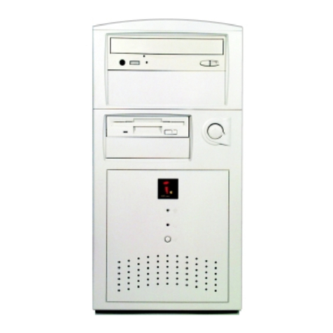
iDOT M2 System Instruction Manual


2
FCC Declaration of Conformity
This device complies with Part 15 of the FCC Rules. Operation is subject to the
following two conditions: (1) this device may not cause harmful interference, and (2)
this device must accept any interference received, including interference that may
cause undesired operation.
For questions related to the EMC performance of this product, contact:
iDOT.com
Building 6, Suite 100
9715 Burnet Road
Austin, Texas USA 78758 USA
This equipment has been tested and found to comply with the limits for a Class B digital
device, pursuant to Part 15 of the FCC Rules. These limits are designed to provide
reasonable protection against harmful interference in a residential installation. This
equipment generates, uses, and can radiate radio frequency energy and, if not installed
and used in accordance with the instructions, may cause harmful interference to radio
communications. However, there is no guarantee that interference will not occur in a
particular installation. If this equipment does cause harmful interference to radio or
television reception, which can be determined by turning the equipment off and on, the
user is encouraged to try to correct the interference by one or more of the following
measures:
• Reorient or relocate the receiving antenna.
• Increase the separation between the equipment and the receiver.
• Connect the equipment to an outlet on a circuit other than the one to which the
receiver is connected.
Part Number Edition Date
DOC1015 First November 1998
iDOT.computers, iDOT.com, and PCs for Smarties are trademarks of iDOT.com, Inc. All other brand names and
product names are trademarks or registered trademarks of their respective companies.
1998 by iDOT.com, Inc. and Soyo Computer, Inc. All rights reserved. No part of this document may be reproduced
in any form, including translation to another language, without the prior written consent of iDOT.com, Inc.
iDOT.com
Building 6, Suite 100
9715 Burnet Road
Austin, Texas 78758 USA
512-684-5000
www.idot.com

Contents 3
&RQWHQWV
Welcome
Package checklist. . . . . . . . . . . . . . . . . . . . . . . . . . . . . . . . . . . . . . . . . . . . . . . 5
Ordering options and replacement parts . . . . . . . . . . . . . . . . . . . . . . . . . . . . . 6
Contacting iDOT.com . . . . . . . . . . . . . . . . . . . . . . . . . . . . . . . . . . . . . . . . . . . 6
Setting Up Your M2 System . . . . . . . . . . . . . . . . . . . . . . . . . . . . . . . 7
M2 System Hardware
Removing the chassis cover. . . . . . . . . . . . . . . . . . . . . . . . . . . . . . . . . . . . . . 10
Location of main system components . . . . . . . . . . . . . . . . . . . . . . . . . . . . . . 11
Mainboard layout. . . . . . . . . . . . . . . . . . . . . . . . . . . . . . . . . . . . . . . . . . . . . . 12
Front panel connections. . . . . . . . . . . . . . . . . . . . . . . . . . . . . . . . . . . . . . . . . 13
Power LED and keyLock. . . . . . . . . . . . . . . . . . . . . . . . . . . . . . . . . . . 13
Reset. . . . . . . . . . . . . . . . . . . . . . . . . . . . . . . . . . . . . . . . . . . . . . . . . . . 14
Speaker. . . . . . . . . . . . . . . . . . . . . . . . . . . . . . . . . . . . . . . . . . . . . . . . . 14
Turbo LED . . . . . . . . . . . . . . . . . . . . . . . . . . . . . . . . . . . . . . . . . . . . . . 14
IDE LED . . . . . . . . . . . . . . . . . . . . . . . . . . . . . . . . . . . . . . . . . . . . . . . 14
ATX power on/off switch . . . . . . . . . . . . . . . . . . . . . . . . . . . . . . . . . . 14
Back panel connections . . . . . . . . . . . . . . . . . . . . . . . . . . . . . . . . . . . . . . . . . 15
Onboard serial port (COM1) . . . . . . . . . . . . . . . . . . . . . . . . . . . . . . . . 15
Parallel port (PRT). . . . . . . . . . . . . . . . . . . . . . . . . . . . . . . . . . . . . . . . 16
PS/2 keyboard . . . . . . . . . . . . . . . . . . . . . . . . . . . . . . . . . . . . . . . . . . . 16
PS/2 mouse. . . . . . . . . . . . . . . . . . . . . . . . . . . . . . . . . . . . . . . . . . . . . . 16
Universal Serial Bus (USB1 and USB2) . . . . . . . . . . . . . . . . . . . . . . . 16

M2 Systems User’s Handbook
4Contents
Installing and removing RAM. . . . . . . . . . . . . . . . . . . . . . . . . . . . . . . . . . . . 17
Installing DIMMs. . . . . . . . . . . . . . . . . . . . . . . . . . . . . . . . . . . . . . . . . 17
Removing DIMMs . . . . . . . . . . . . . . . . . . . . . . . . . . . . . . . . . . . . . . . . 18
Installing expansion cards . . . . . . . . . . . . . . . . . . . . . . . . . . . . . . . . . . . . . . . 18
Installing hard disk drives and CD-ROM drives. . . . . . . . . . . . . . . . . . . . . . 19
Installing floppy drives . . . . . . . . . . . . . . . . . . . . . . . . . . . . . . . . . . . . . . . . . 20
Device pin assignments . . . . . . . . . . . . . . . . . . . . . . . . . . . . . . . . . . . . . . . . . 20
Wake-On-LAN (JP44) . . . . . . . . . . . . . . . . . . . . . . . . . . . . . . . . . . . . . 20
Infrared (SIR). . . . . . . . . . . . . . . . . . . . . . . . . . . . . . . . . . . . . . . . . . . . 21
CPU cooling fan. . . . . . . . . . . . . . . . . . . . . . . . . . . . . . . . . . . . . . . . . . 21
ATX power supply. . . . . . . . . . . . . . . . . . . . . . . . . . . . . . . . . . . . . . . . 22
Power-on By Keyboard jumper (JP10) . . . . . . . . . . . . . . . . . . . . . . . . . . . . . 23
Clearing and resetting CMOS memory (JP5) . . . . . . . . . . . . . . . . . . . . . . . . 24
Replacing the battery. . . . . . . . . . . . . . . . . . . . . . . . . . . . . . . . . . . . . . . . . . . 25

Welcome 5
:HOFRPH
Package checklist
In addition to this book, your iDOT.com™ M2 systempackage
should include the items listed below. If any item is damaged or
missing, contact the iDOT.com Customer Service Department
at 888-315-9563.
■M2 computer
■mouse
■keyboard
■power cable
■modem cable (if your system includes a modem)
■monitor (if you ordered a monitor)
■Microsoft®Windows®98 documentation, and Certificate of
Authenticity.
Note
The Product ID number, which you’ll need to set up your
system, is on the
Certificate of Authenticity
.

Ordering options and replacement parts
M2 Systems User’s Handbook
6Welcome
Ordering options and replacement parts
For complete information about options and replacement parts
available for your M2 system, see the iDOT.com Web site:
www.idot.com.
Contacting iDOT.com
For the most up-to-date information about your M2 system and for
sales or technical support, go to the iDOT.com Web site at
www.idot.com. You can also contact iDOT.com at these numbers:
Customer Service 888-315-9563
Sales 888-388-4368
Technical Support 888-316-6302

Setting Up Your M2 System 7
6HWWLQJ8S<RXU06\VWHP
¯Plug thepower cable
into the back of the
M2 system. Make
sure the plugs are
firmly seated in their
sockets.
°Plug in the keyboard
and the mouse.
Remove the
protective shield
from the ball on the
bottom of the mouse.
±Connect one end of
the monitor cable to
the M2 video port
and the other end to
the monitor.
Plug the monitor
into a power outlet.
²Plug the left speaker cable
into the right speaker input
jack. Plug the speaker’s
power adapter into the
DC jack on the back of
the right speaker. Plug the
green speaker cable into
the port on the back of the
M2 system.
Plug the adapter into a
power strip or surge
protector.*
³Connect the modem
to the PHONE jack.
Connect one end of
the phone line to the
LINE jack and the
other end to the wall
jack.
´If you have a USB
device, connect it.
Connect your printer.
If you have a serial
device, connect it
to the COM1 port.
µMake sure all power
cables are plugged into
power outlets.
iDOT.com recommends
that you use a surge
protector or UPS
(uninterruptible power
supply).
¶Turn on the printer first, then the monitor,
speakers, and computer. The system power
switch is located on the back of the computer;
the secondary switch is on the front.
The speakers’ power switch is on the back of
the right speaker.
*On conventional power strips, you may want to position the adapter near
the end of the strip, because the adapter may cover more than one outlet.

M2 Systems User’s Handbook
8

M2 System Hardware 9
06\VWHP+DUGZDUH
This chapter provides instructions for changing or upgrading
M2 system hardware.
Static electricity can damage integrated circuits. Before
handling any computer component outside its protective
packaging, use one of these methods to discharge static
electricity in your body:
• After you turn off the main switch on the back of the computer
and remove the chassis cover, touch a metal computer
component (such as the power supply).
or
• Wear a static wrist strap that is connected to a natural earth
ground.
Do not handle add-on cards by their “gold finger” connectors.
Fingers have oils and other contaminants that can prevent
connectors from making an electrical connection, which may
cause errors or other malfunctions. Handle all system
components by their mounting brackets or other edges.
Warning

Removing the chassis cover
M2 Systems User’s Handbook
10 M2 System Hardware
Removing the chassis cover
1. Turn off all peripheral devices connected to the system.
2. Turn off the primary power switch on the back of the system.
3. Unplug the system’s power cord.
Follow the steps shown in the illustration:
4. Press
pressure-release
tabs.
5. Pull the side
panel out, away
from the system.

M2 Systems User’s Handbook
Location of main system components
M2 System Hardware 11
Location of main system components
power supply
expansion slots
mainboard
CD-ROM
drive
floppy disk
drive
hard disk
drive
front of
system

Mainboard layout
M2 Systems User’s Handbook
12 M2 System Hardware
Mainboard layout
M
1
PRT
S
B 1 USB 2
PS/2 KB
Connector PS/2 Mouse
Connector
G
A
U
T
C
K
JOYSTICK
ISA Slot #2
JP2
JP1
JP5
13
1
CPUFAN
IDE 1IDE 2
1
1
1FDC
ISA Slot #1
ATX
Power
DIMM 1
DIMM 2
Speaker
Keylock
Power
LED Reset
PWRBT
Turbo
LED
HDD LED
_
+
_
+
_
+
_
+
Flash BIOS
PCI Slot #1
PCI Slot #2
1
SIR 3V
Lithium
Battery
SiS 5598
Chipset
60&
®
FDC37C669Q
ALS120
JP30
35791
268104
J4 J5
JP44
13
COM 2
J2
14
14
JP10
JP11
JP12
JP14
JP16
JP15
JP13
321
321
12 34 JP17
JP22
WOL
Header

M2 Systems User’s Handbook
Front panel connections
M2 System Hardware 13
Front panel connections
Refer to the following figure to locate front panel connectors.
Power LED and keyLock
Plug the power LED cable into the 5-pin keylock connector.
Some systems feature a keylock function with a front panel switch for
enabling or disabling the keyboard. Connect the keylock switch to the
5-pin keylock connector on the mainboard.
Pin assignments
Device Pins
keylock 4, 5
power LED 1, 3

Front panel connections
M2 Systems User’s Handbook
14 M2 System Hardware
Reset
When the Reset cable is connected, pushing the Reset button on the
front panel causes the system to restart the boot-up sequence.
Plug the Reset push-button cable intothe 2-pin Reset connector on the
mainboard.
Speaker
Connect the 4-pin PC speaker cable from the case to the Speaker
connector on the mainboard.
Turbo LED
Connecting the 2-pin turbo LED cable to the corresponding Turbo
LED connector causes the LED to light when the system is in Turbo
mode. (The manufacturer has permanently set this mainboard to
Turbo mode.)
IDE LED
When the IDE LED cable is connected, the LED lights when an IDE
device (a hard disk drive or a CD-ROM) is active.
Connect the 2-pin IDE device LED cable to the corresponding IDE
LED connector on the mainboard.
ATX power on/off switch
Connecting the switch enables the ATX power supply to be turned on
and off. Connect the 2-pin momentary-type switch to the PWRBT
connector.

M2 Systems User’s Handbook
Back panel connections
M2 System Hardware 15
Back panel connections
Connectors for external devices such as the PS/2 keyboard, PS/2
mouse, printer, modem, and USB are located on the mainboard back
panel.
Refer to the following figure to locate back panel connectors.
Onboard serial port (COM1)
Plug the cable of the serial device (such as a mouse or a modem) into
the COM1 9-pin male connector on the rear panel.
USB 1 USB 2
PS/2 mousePS/2 keyboard
COM1
VGA PRT
Line out
Line in
Microphone joystick

Back panel connections
M2 Systems User’s Handbook
16 M2 System Hardware
Parallel port (PRT)
Plug the cable of the parallel device (such as a printer) into the 26-pin
female connector on the rear panel.
PS/2 keyboard
Plug the keyboard connector into the 6-pin female PS/2 keyboard
connector on the rear panel.
PS/2 mouse
Plug the mouse connector into the 6-pin femalePS/2 mouse connector
on the rear panel.
Universal Serial Bus (USB1 and USB2)
Plug the USB device connector into the USB1 or USB2 connector.

M2 Systems User’s Handbook
Installing and removing RAM
M2 System Hardware 17
Installing and removing RAM
The M2 mainboard features two sockets for DIMMs from 8 to
128 MB. You can install the memory in any combination; there are no
special memory combination restrictions, other than the following:
■Do not install EDO DIMMs in combination with SDRAM
DIMMs.
■In order to use the onboard VGA with a single DRAM module,
this single DRAM must be installed in bank DIMM1.
Installing DIMMs
1. Locate the DIMM slots on the mainboard. (See page 12.)
2. Use both hands to press the DIMM straight down into the
DIMM socket.
When the DIMM is properly seated, the clips of the socket snap
in place to hold the DIMM on either side.

Installing expansion cards
M2 Systems User’s Handbook
18 M2 System Hardware
Removing DIMMs
Gently press down both clips on each side of the DIMM to remove
the DIMM.
Installing expansion cards
Your M2 system features the following slots for expansion cards
(as shown on page 12):
■two PCI bus slots
■two ISA bus slots.
Turn off the primary system power switch on the back of the
computer before installing or removing any device.
Observe static electricity precautions. See the warnings on
page 9.
1. Remove the chassis cover.
2. Select an empty expansion slot and remove the corresponding slot
cover. Keep the slot cover mounting screw nearby.
Caution
See “Removing the
chassis cover” on
page 10.

M2 Systems User’s Handbook
Installing hard disk drives and CD-ROM drives
M2 System Hardware 19
3. Holding the edge of the expansion card, carefully align the edge
connector with the expansion slot.
4. Push the card firmly into the slot by pushing down on one end of
the card, then the other. Use this rocking motion until the card is
firmly seated in the slot.
5. Secure the board with the mounting screw you removed in step 2.
6. Make sure the card has been placed evenly and completely into
the expansion slot.
Installing hard disk drives and CD-ROM drives
The M2 mainboard offers two primary and secondary IDE device
connectors: IDE1 and IDE2. It can support up to four high-speed
HDD or CD-ROM devices.
Connect one side of the 40-pin flat cable to the IDE device (HDD or
CD-ROM). Plug the other end to the primary (IDE1) or secondary
(IDE2) directionally-keyed IDE connector on the mainboard.
(See page 12).

Installing floppy drives
M2 Systems User’s Handbook
20 M2 System Hardware
Installing floppy drives
The M2 system supports five types of floppy drives: 720KB, 1.2 MB,
1.44 MB, 2.88 MB, and LS-120. The mainboard also supports a
3-mode (720 KB/1.2 MB/1.44 MB) floppy drive commonly used in
Japan. The mainboard can support up to two floppy drives.
Connect one side of the 34-pin flat cable (labeled FDC) to the floppy
drive. Plug the other end to the floppy drive connector on the
mainboard. (See page 12).
Device pin assignments
This section contains information about pin assignments for devices
connected to the M2 mainboard.
Wake-On-LAN (JP44)
The LAN card that supports the Wake-On-LAN (WOL) function
connects to the JP44 connector on the mainboard.
Wake-On-LAN
JP44 Pin Assignment
GND
1
2
3
MP-Wakeup
5VSB
Other manuals for M2 System
1
Table of contents
Other iDOT Desktop manuals
Popular Desktop manuals by other brands

Dell
Dell Precision Workstation 380 Quick reference guide
Digital Equipment
Digital Equipment MicroVAX 3100 85 Troubleshooting and Diagnostics Information
Lenovo
Lenovo H430 Specifications
HP
HP Vectra VE5 4 supplementary guide

HP
HP Kayak XA supplementary guide
Dell
Dell OptiPlex GX60 Setup and quick reference guide
