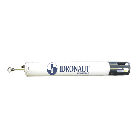
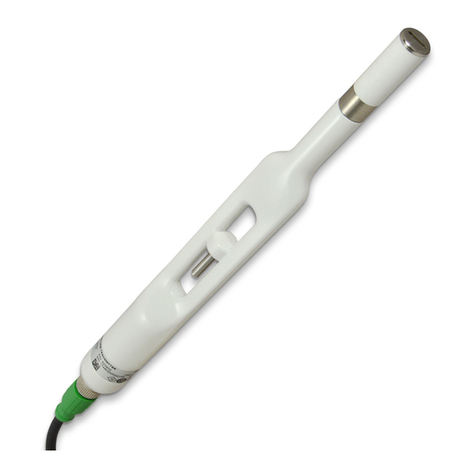
idronaut Ocean Seven 311 User manual

OCEAN SEVEN 311
Digital pH PROBE
Copyright @ 1982 –2019 Idronaut S.r.l. All rights reserved.
OCEAN SEVEN and Idronaut are registered trademarks of Idronaut S.r.l.
Other products and services mentioned in this document are identified by the trademarks or service marks of their respective companies
or organizations. No part of this publication, or any software included with it, may be reproduced, stored in a retrieval system, or
transmitted in any form or by any means, including photocopying, electronic, mechanical, recording or otherwise, without the prior
written permission of the copyright holder. Idronaut S.r.l. provides this document as is without warranty of any kind either expressed or
implied including, but not limited to, the implied warranties of merchantability and fitness for a particular purpose. Idronaut S.r.l. may
make changes of improvements in the equipment, software, firmware, or specifications described in this document at any time and
without notice. These changes may be incorporated in new releases of this document. This document may contain technical inaccuracies
or typographical errors. Idronaut S.r.l. waives responsibility of any labour, materials, or costs incurred by any person or party as a result
of using this document. Idronaut S.r.l. shall not be liable for any damages (including, but not limited to, consequential, indirect or
incidental, special damages, or loss of profits or data) even if they were foreseeable and Idronaut S.r.l. has been informed of their potential
occurrence arising out of or in connection with this document or its use.
IDRONAUT S.r.l
Via Monte Amiata, 10 20861 –Brugherio (MB) –ITALY
Tel: +39 039 879656 / 883834 Fax: +39 039883382

IDRONAUT –Brugherio (MB) OCEAN SEVEN 311 04-2019
OCEAN SEVEN 311
IMPORTANT REMARKS
pH MEASUREMENT
The pH and reference sensors should never be allowed to dry out. For short-term storage of up to
one day, the probe’s sensor head can simply be immersed in water. If the probe remains unused for
periods longer than one day, always place the hydrating caps on both sensors. The pH sensor cap
should be filled with the pH7 Buffer Solution (or simply with clean water). The reference sensor cap
should be filled with the IDRONAUT Reference Sensor Storage Solution.
BATTERY REPLACEMENT/RECHARGING
➢To gain access to the internal batteries, loosen the closing screws on the probe top cover with
a proper screwdriver. Remove all water droplets around the top cover to prevent the
penetration of moisture inside the housing.
➢Install two new 1.5V AA Alkaline cells in the double-battery holder or a new Lithium 3.6V
cell in the single-battery holder. INSTALLING TWO 3.6V LITHIUM BATTERIES IN THE
DOUBLE-BATTERY HOLDER AND CONNECTING IT TO THE OS311 TOP COVER
WILL CAUSE A PERMANENT DAMAGE TO THE OS311 PROBE ELECTRONICS.
➢If the probe is not to be used for long periods (weeks or more),we strongly suggest removing
the internal battery from the probe. This will eliminate the possibility of damaging the
electronic circuitry in case of battery leakage.
SELF-RECORDING USE
➢The internal Real-Time Clock (RTC) keeper is powered by the probe main battery. If the
battery is fully dead or disconnected, the RTC loses the date & time. It is mandatory to set
up the RTC or check that the RTC date & time are correct before starting a self-recording
data acquisition cycle.
➢The probe is equipped with a rotary magnetic power ON/OFF switch, present on the top
cover. The probe is ON when the switching arm is rotated as indicated on the top cover label.
Once the self-recording configuration of the probe has been set, the probe can be switched
OFF and ON again at the sampling site, when it is ready for deployment.
VERY IMPORTANT: Allow a 30-second interval between each ON/OFF cycle.
PROBE WASHING
After use, the probe must be always washed with fresh water in order to remove any salt water
residual or dirtiness.
LIFETIME AND HOW TO REPLACE THE IDRONAUT SENSORS
The IDRONAUT sensors are all pressure compensated and, in particular, the temperature sensor
can last many years, if properly used. All sensor heads have a standard 12 mm diameter and are
provided with two o-rings (Parker 2-12) for sealing. This means that every sensor can be fitted in
any of the four sensor head holes.

IDRONAUT –Brugherio (MB) OCEAN SEVEN 311 04-2019
TABLE OF CONTENTS
1. PROBE DESCRIPTION ............................................................................................................................... 3
1.1. SAMPLING MODES ................................................................................................................................... 3
1.2. REAL TIME COMMUNICATION............................................................................................................. 3
1.3. LABORATORY STANDARD RS232C INTERFACE............................................................................... 3
1.4. WIRELESS COMMUNICATIONS “BlueTooth” ..................................................................................... 4
1.5. INTERNAL BATTERY PACK .................................................................................................................... 4
1.5.1. Optional rechargeable battery pack........................................................................................................... 5
1.6. PROBE POWER ON/OFF SWITCH........................................................................................................... 5
1.7. INTERFACING WINDOWS PROGRAMMES......................................................................................... 5
1.8. FIRMWARE OVERVIEW............................................................................................................................ 5
1.8.1. User interface................................................................................................................................................ 6
1.8.2. Probe Access Rights ..................................................................................................................................... 6
1.8.3. Menu header structure ................................................................................................................................ 7
1.8.4. Data transmission protocols ....................................................................................................................... 7
1.8.5. Point-to-point protocol................................................................................................................................ 7
1.8.6. Verbose and non-verbose special characters............................................................................................ 7
1.8.7. Field upgradeable firmware ....................................................................................................................... 7
1.8.8. Low power consumption ............................................................................................................................ 7
1.8.9. Configuration and Calibration ................................................................................................................... 8
1.8.10. Menu & submenu structure........................................................................................................................ 8
1.9. SENSOR SPECIFICATION ......................................................................................................................... 9
1.10. THE SENSORS ............................................................................................................................................. 9
1.10.1. The temperature sensor............................................................................................................................... 9
1.10.2. pH and reference sensors............................................................................................................................ 9
1.11. PHYSICAL CHARACTERISTICS............................................................................................................ 11
2. INSTALLATION AND START-UP ......................................................................................................... 12
2.1. SHIPPING LIST.......................................................................................................................................... 12
2.2. INSTALLATION PROCEDURE .............................................................................................................. 12
2.3. HOW TO OPERATE THE probe ............................................................................................................. 12
2.4. START-UP PROCEDURE ......................................................................................................................... 12
2.4.1. Start-up - Verbose operating mode ........................................................................................................ 12
2.4.2. Start-up Non-verbose operating mode ................................................................................................... 13
2.5. The Main Menu .......................................................................................................................................... 13
3. COMMANDS ............................................................................................................................................. 14
3.1. SHUTDOWN.............................................................................................................................................. 14
3.2. DATA ACQUISITION............................................................................................................................... 14
3.2.1. Real Time..................................................................................................................................................... 14
3.2.2. Linear Profile .............................................................................................................................................. 14
3.2.3. Timed acquisition....................................................................................................................................... 14
3.2.4. Continuous Sampling................................................................................................................................ 15
3.2.5. Conditional Sampling................................................................................................................................ 16
3.2.6. Burst Sampling ........................................................................................................................................... 17
3.3. CALIBRATION .......................................................................................................................................... 18
3.3.1. Temperature sensor calibration.................................................................................................................. 18
3.3.2. pH sensor calibration................................................................................................................................. 19
3.4. MEMORY MANAGEMENT .................................................................................................................... 20
3.4.1. Memory priming ........................................................................................................................................ 20
3.4.2. Memory Status............................................................................................................................................ 20
3.4.3. Show stored data........................................................................................................................................ 20
3.4.4. Delete Cast .................................................................................................................................................. 20

IDRONAUT –Brugherio (MB) OCEAN SEVEN 311 04-2019
3.4.5. Initialize Memory....................................................................................................................................... 21
3.5. SERVICE MENU ........................................................................................................................................ 21
3.5.1. Set-up........................................................................................................................................................... 21
3.5.2. Real-time Clock set-up .............................................................................................................................. 23
3.5.3. Raw Counts or Raw mV............................................................................................................................ 23
3.5.4. Rights ........................................................................................................................................................... 23
3.5.5. Firmware ..................................................................................................................................................... 23
3.5.6. Diagnostics.................................................................................................................................................. 24
3.6. CHANGE OPERATING MODE .............................................................................................................. 24
4. SELF RECORDING.................................................................................................................................... 25
4.1. UNATTENDED ACQUISITION IN FUNCTION OF TIME INCREMENTS..................................... 25
4.1.1. Preliminary configuration......................................................................................................................... 25
4.1.2. Field operations.......................................................................................................................................... 26
4.1.3. Ending the unattended data acquisitions ............................................................................................... 26
4.2. UNATTENDED PROFILES USING THE CONTINUOUS ACQUISITION FUNCTION ................ 26
4.2.1. Preliminary configuration......................................................................................................................... 26
4.2.2. Field operations.......................................................................................................................................... 26
4.2.3. Ending the unattended data acquisitions ............................................................................................... 27
4.3. UNATTENDED PROFILES USING THE CONDITIONAL ACQUISITION..................................... 27
4.3.1. Preliminary configuration......................................................................................................................... 27
4.3.2. Field operations.......................................................................................................................................... 28
4.3.3. Ending the unattended data acquisitions ............................................................................................... 28
4.4. UNATTENDED BURST SAMPLING...................................................................................................... 28
4.4.1. Preliminary configuration......................................................................................................................... 28
4.4.2. Field operations.......................................................................................................................................... 29
4.4.3. Ending the unattended data acquisitions ............................................................................................... 29
4.5. UPLOADING THE DATA STORED IN THE PROBE MEMORY....................................................... 30
4.5.1. WINDOWS “WTERM or ITERM” ........................................................................................................... 30
4.6. UNATTENDED ACQUISITIONS - IMPORTANT TIPS....................................................................... 30
4.6.1. Power consumption reduction................................................................................................................. 30
4.6.2. ON/OFF cycles............................................................................................................................................ 30
4.6.3. Shipping conditions................................................................................................................................... 30
4.6.4. Sensors......................................................................................................................................................... 30
4.6.5. Probe autonomy ......................................................................................................................................... 30
5. ITERM –WINDOWS TERMINAL EMULATION PROGRAMME..................................................... 32
5.1. DISTRIBUTED FILES................................................................................................................................. 32
5.2. ITERM- INSTALLATION ......................................................................................................................... 32
5.3. WTERM - INSTALLATION ..................................................................................................................... 32
5.3.1. Tools............................................................................................................................................................. 32
6. INTERNAL BATTERIES ........................................................................................................................... 33
6.1. AISI316L & Titanium HOUSING Battery rEPLACEMENT procedure.............................................. 33
6.2. POM HOUSING - Battery rEPLACEMENT procedure....................................................................... 34
6.3. Optional Rechargeable Battery PACK .................................................................................................... 34
6.3.1. Battery recharging procedure................................................................................................................... 34
6.4. Battery Endurance...................................................................................................................................... 35
6.5. RTC and Battery ......................................................................................................................................... 35
7. PTP COMMUNICATION PROTOCOL.................................................................................................. 36
APPENDIX A –“BLUETOOTH” WIRELESS MODULE ..................................................................................... 37
APPENDIX B –SUBMERSIBLE CONNECTORS AND CABLE CARE ............................................................ 38
Software updates and technical support
Website download area for software updates and technical support: http://www.idronaut.it/download

IDRONAUT –Brugherio (MB) OCEAN SEVEN 311 04-2019
Warranty
The OCEAN SEVEN 311 is covered by a one-year limited warranty that extends to all parts and labour and
covers any malfunction that is due to poor workmanship or due to errors in the manufacturing process. The
warranty does not cover shortcomings that are due to the design, nor does it cover any form of consequential
damage because of errors in the measurements. If there is a problem with your OCEAN SEVEN 311, first try
to identify the problem by following the procedure outlined in the troubleshooting section of this manual.
Please contact your representative or IDRONAUT S.r.l. if the problem is identified as a hardware problem or
if you need additional help in identifying the problem. Please make sure to contact IDRONAUT S.r.l. to
obtain the relevant instructions before the OCEAN SEVEN 311 or any module is returned to IDRONAUT
(see cleaning instructions).
For systems under warranty, IDRONAUT S.r.l. will attempt to ship replacement parts before the
malfunctioning part is returned. We encourage you to contact us immediately if a problem is detected and we
will do our best to minimize the downtime. Every effort has been made to ensure the accuracy of this manual.
However, IDRONAUT S.r.l. makes no warranties with respect to this documentation and disclaims any
implied warranties of merchantability and fitness for a particular purpose. IDRONAUT S.r.l. shall not be liable
for any errors or for incidental or consequential damages in connection with the furnishing, performance or
use of this manual or the examples herein. The information in this document is subject to change without
notice.
Cleaning Instructions
Before the returned OCEAN SEVEN 311 can be serviced, equipment exposed to biological, radioactive, or toxic
materials must be cleaned and disinfected. Biological contamination is presumed for any instrument, probe or
other device that has been used with wastewater. Radioactive contamination is presumed for any instrument,
PROBE or other device that has been used near any radioactive source. If an OCEAN SEVEN 311, or other part
is returned for service without following the cleaning instructions, and if in our opinion it represents a
potential biological or radioactive hazard, our service personnel reserve the right to withhold service until
appropriate cleaning, decontamination has been completed. When service is required, either at the user's
facility or at IDRONAUT, the following steps must be taken to insure the safety of our service personnel.
➢In a manner appropriate to each device, decontaminate all exposed surfaces, including any containers.
70% isopropyl alcohol or a solution of 1/4 cup bleach to 1-gallon tap water are suitable for most
disinfecting. Instruments used with wastewater may be disinfected with 5% Lysol if this is more
convenient to the user.
➢The user shall take normal precautions to prevent radioactive contamination and must use
appropriate decontamination procedures should exposure occur. If exposure has occurred, the
customer must certify that decontamination has been accomplished and that no radioactivity is
detectable by survey equipment.
➢Any product being returned to the IDRONAUT S.r.l. laboratory for service or repair should be packed
securely to prevent damage.
➢Cleaning must be completed on any product before returning it to IDRONAUT S.r.l.
Disposal of Waste Equipment by Users in the European Union
The recycling bin symbol on the product or on its packaging indicates that this product must not be disposed
of with your other waste. It is your responsibility to dispose of your waste equipment by handling it over to a
designated collection point for the recycling of waste electrical and electronic equipment. The separate
collection and recycling of your waste equipment at the time of disposal will help to conserve natural resources
and ensure that it is recycled in a manner that protects human health and the environment. For more
information about where you can drop off your waste equipment for recycling, please contact your local city
office, your waste disposal service.

SECTION ONE –PROBE DESCRIPTION
IDRONAUT –Brugherio (MB) OCEAN SEVEN 311 04-2019
3
1. PROBE DESCRIPTION
The OCEAN SEVEN 311 completes the line of high quality and accuracy IDRONAUT OCEAN SEVEN
PROBEs, fulfilling the demand of a high-performance digital pH PROBE with very small diameter and
very low power consumption.
The OS311 is specifically designed to simplify the monitoring of pH in fresh and saline waters. A
temperature sensor is included to automatically compensate the pH readings. High quality long life
IDRONAUT pH and Reference (KCl or NaCl) sensors.
This PROBE can be easily integrated/adapted to third-party systems like floating profilers and/or
oceanographic moorings, CTD, ROVs, ASVs and AUVs. The OS311 does not require pumps or any other
external device to flush the sensors, which minimizes its power consumption and allows the use in
Arctic and Antarctica. The OS311 standard interface is RS232C; other optional interfaces are: TTL, RS485
and wireless Bluetooth®. The RS485 interface overcomes the RS232C limitation (max 200m cable). The
OS311 can communicate at speeds up to 115k2 bps, thus minimizing data uploading time. The OS311
can be manufactured with the following housings: AISI 316 stainless steel/POM (plastic), whole POM,
composite titanium/POM or whole titanium and can be deployed to depths of 1000m, 2000m, 4000m or
7000m respectively.
1.1. SAMPLING MODES
User selectable sampling/operating modes include:
Real time: Data is sampled at the maximum rate, 8Hz and transmitted.
Continuous: Data is sampled at configurable sampling rates starting from 0.1 Hz to 8 Hz. Sampling
continues until interrupted. Multiple cycles can be possible by switching the PROBE
ON and OFF.
Timed: PROBE collects a series of samples and then sleeps for the configured time interval
before waking up again and repeating the acquisitions. Time interval can be
configured between 5s and 1 day. Battery power is conserved while the PROBE is in
sleep mode. This data acquisition method is ideal for long-term monitoring.
Conditional: Data acquisition is started and continues while the reading from a selected sensor is
above a threshold value. Monitoring of the selected sensor threshold value can be
configured to occur at intervals: between 5s and 1day.
Burst: 8 Hz measurements can be performed at configured time intervals between 5s and 1
day. Battery power is conserved by switching off the PROBE between bursts.
1.2. REAL TIME COMMUNICATION
The OCEAN SEVEN 311 communicates with a computer via a standard RS232C interface. Real-time
data can be acquired by means of the WTERM or ITERM Windows IDRONAUT software. The optional
RS485 interface overcomes the limitation of the RS232C cable maximum length (200 m) and allows the
probe to transmit data through distances up to 1000 m. The communication speed is user selectable
among: 4800, 9600, 19200, 38400, 57600 and 115200 bps. The default speed is 38K4.
Connection type
Max cable length
Max. transfer rate
RS232C / RS485
10 m
115200 bps
RS232C
200 m
38400 bps
RS485
1000 m
38400 bps
1.3. LABORATORY STANDARD RS232C INTERFACE
The RS232C interface allows direct connection between the probe and a personal computer by means of
the six-pole male connector located on the top end cap of the probe. RS232 cable, up to 200m long, can
be prepared upon request. The below pictures and wiring diagrams show standard laboratory cable.

SECTION ONE –PROBE DESCRIPTION
IDRONAUT –Brugherio (MB) OCEAN SEVEN 311 04-2019
4
1.4. WIRELESS COMMUNICATIONS “BLUETOOTH”
The OCEAN SEVEN 311 can be optionally equipped with a Bluetooth module which allows full-duplex
communications between the probe and a personal computer (Desktop, Laptop) or PDA devices
equipped with a compatible Bluetooth™ device. The wireless adapter is based on the well-known and
diffused Bluetooth™ standard and is designed to provide an interface conforming to the Bluetooth™
v1.1 class 1. The operating range of the adapter is specified in 100m although line of sight ranges of
300m can be achieved. However, if a class-2 Bluetooth™ device is used to communicate with the probe
then the range will be limited to 10-20m as foreseen by class-2 devices. The probe Bluetooth interface
allows instant wireless connectivity to any device supporting a compatible Bluetooth™ SPP protocol.
The connection with the probe among the Bluetooth™ devices registered on the network is guaranteed
by means of the unique 8-digit PIN code, which identifies each probe. The installation of the Bluetooth
module considerable decreases the lifetime of the probe internal batteries
1.5. INTERNAL BATTERY PACK
The OCEAN SEVEN 311 housing has, in its upper part enough space to
accommodate an internal battery pack. The OS311 is powered by a single 3.6V
battery or two Alkaline 1.5V batteries; different types of battery can be installed
in the probe housing. Together with the probe IDRONAUT ships two plastic
battery holders for the single Lithium or the double Alkaline batteries.
IDRONAUT does not include the batteries in the probe shipment.
➢2 x size “AA”Alkaline 1.5V battery assembled in a single pack 3.0V
➢1 x size "AA"Lithium non rechargeable battery 3.6V, 2.4Ah
➢1 x size “C” Lithium non rechargeable battery 3.6V, 8.4Ah
➢1 x size “D” Lithium non rechargeable battery 3.6V, 19 Ah
➢IDRONAUT rechargeable custom battery pack 3.6V, 4.2Ah

SECTION ONE –PROBE DESCRIPTION
IDRONAUT –Brugherio (MB) OCEAN SEVEN 311 04-2019
5
INSTALLING TWO 3.6V LITHIUM BATTERY IN THE DOUBLE
ALKALINE BATTERY HOLDER AND CONNECTING IT TO THE OS311
TOP COVER WILL CAUSE A PERMANENT DAMAGE TO THE OS311
PROBE ELECTRONICS.
When the probe is not used for long periods (e.g. 2 weeks or more), we suggest
disconnecting the internal battery pack connector from the probe electronics or removing the internal
battery pack from the probe to prevent the internal batteries from damaging the probe due to battery
acid leakage. This is why the OCEAN SEVEN 311 is shipped without batteries installed. The status of
the internal battery pack can be derived from the battery diagnostic reading on the probe start-up
message.
1.5.1. Optional rechargeable battery pack
An IDRONAUT custom rechargeable battery pack (3.6VDC, 4.2Ah) is
available upon request. It comes complete with an international battery
charger. Please be aware that it is not possible to recharge the batteries when
they are installed inside the probe. Therefore, the probe top cover must be
opened to recharge the internal battery pack.
1.6. PROBE POWER ON/OFF SWITCH
The OCEAN SEVEN 311 is equipped with a rotary magnetic switch which acts as
an ON/OFF switch. This switch allows the operator to easily deploy a pre-
configured probe which, when it is on the sampling site, will start to acquire data according to the pre-
configured cycle. It is important to wait at least 30 seconds between consecutive ON/OFF cycles. The below
pictures show the top covers according to the AISI, POM and Titanium housings.
Housing Ø 75mm Housing Ø 48mm
OS311 - STD OS311- STD
White POM Titanium
1.7. INTERFACING WINDOWS PROGRAMMES
IDRONAUT programmes designed for any type of Windows operating systems allow the operator to
communicate with the OCEAN SEVEN 311 to perform attended or unattended data acquisitions.
Programmes include functions to upload data from the internal memory when the probe acts as a
logger. The programme packages comprise:
WTERM / ITERM:
Terminal Emulation Programme and probe management. It simplifies the communications
with the OCEAN SEVEN 311. Diagnostic and probe dedicated functions are provided under
the “PROBE” menu.
1.8. FIRMWARE OVERVIEW
The OS311 is provided with a firmware that manages all the probe operations. The most important
management functions are described in the following subsections.

SECTION ONE –PROBE DESCRIPTION
IDRONAUT –Brugherio (MB) OCEAN SEVEN 311 04-2019
6
1.8.1. User interface
Whenever the probe runs in “VERBOSE MODE”, interaction with the user is carried out by means of
the "USER INTERFACE". With the term “USER INTERFACE” or "MMI" (Man Machine Interface), we
mean the firmware layers that react to the user input and instruct the lower layers of the firmware to
perform the desired action. The "USER INTERFACE" is a so-called menu driven interface, that is, at any
time it is possible to select just one option among various possible choices. Each option will in turn
perform the desired action or invoke a sub-menu containing further topics. The "USER INTERFACE"
makes extensive use of different kinds of menus, among which we have: menu, sub-menus and data
entry menus. A brief and exhaustive description of these menus will follow in the next subsections.
1.10.1.1 Menu & Submenus
A menu is shown mentioning first the menu title, firmware release and current date & time and then a
list of the available items, one for each line. Each item is shown with a digit contained in two square
brackets followed by an explanatory message. The programme has one main menu and four submenus.
The "MAIN MENU", which is shown at the end of the "START-UP PROCEDURE", allows the selection
of the underlying menus. To select an item (and invoke the related submenu), the user must enter the
number contained in the square brackets. Once one of the submenus is shown, it is possible to return to
the upper layer by means of the [0] key. The <ENTER> key re-displays the shown menu.
1.10.1.2 Data entry functions
These kinds of functions allow the user to modify the shown items. The way the items are modified
depends on the type of data itself. A set of rules guides the user during the item modification:
✓The <ENTER> key, whenever the item is shown, skips the data entry to the next available item,
without changing the item itself.
✓Any key different from <ENTER> starts data entry for the shown item.
✓Whenever the modification of the item starts, the <ENTER> key confirms the new item.
✓The numerical entry is automatically range checked. If the modified value is outside the range,
this is shown and the user is requested to re-enter the data.
✓Numerical data input is performed following the English rules such as “.” for the decimal point.
The introduction of coefficients can be accomplished by means of the exponent notation (i.e.
10e-37).
1.8.2. Probe Access Rights
The OCEAN SEVEN 311 configurations and functions are password protected to avoid unwanted
modifications or running of functions that can led to probe unpredictable behaviours. In the probe
service menu, it is present a command <Rights>, which allows the operator to modify the probe access
rights.
Three different access rights are foreseen:
USR User access to perform daily operations and standard probe configuration and management. At
this level, it is not possible to modify certain sensor configuration or probe operating
parameters. Moreover, some probe commands are hidden.
SRV Service access to allow the operator to carry out advanced set-up and advanced diagnostic
functions.
ADM Administrative access to allow full control of the OCEAN SEVEN 311. This access is reserved
to IDRONAUT technicians or to trained operators. Upon request and under IDRONAUT
supervision, administrative access can be granted to the operator to carry out dedicated
functions or configurations.
The probe access right is indicated on the menu headers with an acronym shown inside {} brackets as
above described. At the start-up, the probe operates in user “USR” mode. Service or Administrator
access must be configured using the access rights command. Once the access rights command is
invoked, the following message appears on screen:
Set the PROBE Access rights<<
The customer must reply to the password request with a 10-character message. The possible answers
are:

SECTION ONE –PROBE DESCRIPTION
IDRONAUT –Brugherio (MB) OCEAN SEVEN 311 04-2019
7
“SERVICE311”to grant SERVICE access to the probe functions and configuration.
“****************” to grant ADMINISTRATIVE access to the probe. Administrative password
can be obtained from IDRONAUT only.
The modification of the access right remains valid until the probe is switched off or the access right is
modified. Typing an arbitrary password causes the probe access right to switch to the USR level.
1.8.3. Menu header structure
The menu and submenu show a list of commands preceded by header lines, which identify the menu
or submenu and show the relevant information about the probe in square, round and glyph brackets.
OCEAN SEVEN 311 - ID:311-0010101 {USR}[9.0_00-02/2012] 14:21:09.01 11-07-2012
Where:
OCEAN SEVEN 311 Type of probe and name.
ID:0010101 Serial number.
{USR} Indicates the access rights to the probe functions and configuration.
[9.0_00 02/2012] firmware release number and release date.
1.8.4. Data transmission protocols
Whenever the probe runs in “NON-VERBOSE MODE”, interaction with the user is performed by means
of the "DATA TRANSMISSION PROTOCOL". Selection among the data transmission protocols can be
done by means of the configuration parameters.
1.8.5. Point-to-point protocol
The ASCII based protocol is easy to use and allows data transmissions point by point. The protocol
implies bidirectional half-duplex data transmission between the probe and a PC. The probe, which is
always the slave device, does not send any message unless requested by the master PC.
1.8.6. Verbose and non-verbose special characters
Some special characters are used by the OCEAN SEVEN 311 communication protocol and operator
interface which are associated to special functions:
CTRL-C Interrupts any data acquisition cycle in progress, attended or unattended. Data storing
is completed automatically, the probe operations control returns to the “operator
interface” software module.
CTRL-T Switches the probe immediately from verbose to non-verbose operating mode.
BACKSPACE Allows the operator to delete previously entered characters.
CTRL-J Special character used to terminate the PTP protocol messages.
ENTER Confirms the modified numerical parameters.
1.8.7. Field upgradeable firmware
Like most up-to-date high technology products, the OS311 is equipped with "FLASH" memories. A
special function of the management firmware allows the user to upgrade the firmware to the last release
flawlessly and without opening the probe. Please contact IDRONAUT to obtain the relevant
information and dedicated instructions.
1.8.8. Low power consumption
Probe electronics is accomplished using high integration devices, low power consumption integrated
circuits, and discrete components. The power consumption of the OCEAN SEVEN 311 is very low if
compared to its performance. The low power consumption is further reduced whenever the probe is
not used for more than 1 minute. In fact, the management firmware powers OFF all unused internal

SECTION ONE –PROBE DESCRIPTION
IDRONAUT –Brugherio (MB) OCEAN SEVEN 311 04-2019
8
hardware resources while waiting for a command from the operator. Furthermore, whenever the probe
remains in this low power condition for more than two minutes, it automatically shuts down by itself
thus further reducing the power consumption to less than 8 µAh.
1.8.9. Configuration and Calibration
The OCEAN SEVEN 311 configuration and calibration parameters are stored in a non-volatile memory
which guarantees up to 10.000.000 of write operations and infinite read operations.
1.8.10.Menu & submenu structure
Main Menu
1 - Acquisition
2 - Memory
management
3 - Calibration
4 - Service
5 - Change operating
mode
Memory Management
1 –Memory status
2 –Show stored data
3 –Delete cast
4 - Initialize
Service
1 –Setup
2 –RTC
3 –Raw Counts
4 - Raw mV
5 - Rights
6 - Firmware
7 - Diagnostic
Diagnostics
1 - GPL
2 - FRAM
3 - EERPROM
4 - SCARD
5 - ADC-12bit
6 - Term
7 - Timing
8 - Battery
Data Acquisition
1 –Real time
2 –Pressure
3 –Timed
4 –Continuous
5 –Conditioned
6 –Burst

SECTION ONE –PROBE DESCRIPTION
IDRONAUT –Brugherio (MB) OCEAN SEVEN 311 04-2019
9
1.9. SENSOR SPECIFICATION
The OS311 can be equipped with the following sensors to measure:
Parameter Range Accuracy Resolution Time Constant
Temperature -5.. +35°C 0.01 °C 0.0001 °C 3 s
pH 0.. 14 pH 0.01 pH 0.001 pH 3 s
1.10. THE SENSORS
A short presentation of the IDRONAUT OCEAN SEVEN 311 sensors follows.
1.10.1.The temperature sensor
The temperature sensor is a platinum resistance thermometer (type Pt 100 ohms at 0°
C), fitted on a titanium housing, able to withstand up to 700 bar. The sensor has a
very low response time (3 s) and a high stability of reading with ageing. The drift of
reading (sensor plus associated electronics) is less than 0.0003° C per year.
Type: Pt100@0°C.
Measurement range: -5..+35 °C.
Accuracy: 0.003 °C.
Resolution: 0.0006 °C.
Response time: 50 ms @1 m/s.
Maximum pressure: 700 bar.
Sensor body: Titanium
Life: unlimited.
Calibration frequency: yearly.
Compensation: none.
Maintenance: none.
1.10.2.pH and reference sensors
The measurement of pH in seawater demands high accuracy since seawater has a high ionic strength
and is weakly buffered. The pH range in the oceans is particularly restricted and, only in very special
cases, the observed values are outside the range of 7.8 and 8.4 pH and, in some seas, the range extends
from 6.5 to 9.0 pH. Some problems have always arisen from the use of traditional reference sensors with
porous diaphragms, when measuring the pH in seawater, in particular at pressures in excess of a few
bars, due to the high and variable junction potentials that are generated. The IDRONAUT reference
sensor is in contact with the unknown solution by means of a small hole in the glass tip. This minimizes
and stabilizes the junction potential between the inner gel electrolyte and the liquid to be measured. The
reference sensor is a Silver/Silver Chloride cell in a saturated potassium chloride solid gel and the sensor
head is made of titanium.
It is also available a reference sensor specifically developed for long-term monitoring of seawater where
the internal cell is 0.7 mol NaCl. The glass body of the sensor is fitted with a plastic hydrating cap filled
with the IDRONAUT REFERENCE SENSOR STORAGE SOLUTION based on 3-mol KCl (or NaCl) or,
if not available, even with KCl saturated solution to avoid drying of the gel when not in use. This cap
must be removed before measurements. The pH sensor has a titanium head, a glass body and a pH
sensitive glass tip, which can withstand pressures up to 150 bar or even 700 bar (special version). During
all periods of inactivity, the glass tip must be fitted with a white plastic hydrating cap filled with the pH
7 Buffer Solution, or simply with clean water. This is to prevent the pH-sensitive glass from dehydration,
which slows down the sensor response. This cap must be removed before measurements.

SECTION ONE –PROBE DESCRIPTION
IDRONAUT –Brugherio (MB) OCEAN SEVEN 311 04-2019
10
pH sensor
Type: blue glass membrane.
Measurement range: 0..14 pH
Accuracy: 0.01 pH
Resolution: 0.001 pH
Drift: 0.05 pH/month
Response time: 3 s
Max pressure: 700 bar
Sensor body: titanium
Compensation: automatic thermal compen.
Life: 2 years if intensively used for
monitoring, up to 4 years if used
weekly for daily profiling or
monitoring
Calibration frequency: monthly.
Maintenance: glass membrane renewing using the pH
Sensor Etching Solution.
Reference sensor
Internal cell: Ag/AgCl –using solid gel
Max pressure: 700 bar
Sensor body: titanium
Life: 1 year if intensively used for monitoring, up
to 2 years if used weekly for daily profiling
or monitoring.
Maintenance: stored with the Reference Sensor Storage
Solution.
WARNING
The above stated life performance implies that the pH and reference sensors are
properly hydrated by means of the hydrating plastic cap filled with distilled water
for the pH sensor and with the Reference Sensor Storage solution for the reference
sensor.
STANDARD POTENTIALS OF THE SILVER/SILVER CHLORIDE REFERENCE ELECTRODE FILLED
WITH SATURATED KCl WITH RESPECT TO THE HYDROGEN ELECTRODE
Temperature °C Uo (mV)
0 220,5
5 216,1
10 211,5
15 206,8
20 201,9
25 197
30 191,9
35 186,7
40 181,4
45 176,1
50 170,7
55 165,3
60 159,8
65 154,3

SECTION ONE –PROBE DESCRIPTION
IDRONAUT –Brugherio (MB) OCEAN SEVEN 311 04-2019
11
1.11. PHYSICAL CHARACTERISTICS
Standard versions:
1000 dbar
2000 dbar
2000 dbar
7000 dbar
Dimensions
Housing diameter
43 mm
75 mm
48 mm
48 mm
Total length (with hanging rod)
562 mm
580 mm
560 mm
595 mm
Weight
In air
1.2 kg
2.2 kg
1.5 kg
1.85 kg
In water
0.65 kg
0.5 kg
0.8 kg
1.15kg
Material
AISI316/POM
POM
Titanium/POM
Titanium
Special AUV versions:
1000 dbar
7000 dbar
Dimensions
Housing diameter
43 mm
48 mm
Total length
435 mm
435 mm
Weight
In air
0.9 kg
1.7 kg
In water
0.6 kg
1.1 kg
Material
AISI316L/POM
Titanium

SECTION TWO - INSTALLATION
IDRONAUT –Brugherio (MB) OCEAN SEVEN 311 04-2019
12
2. INSTALLATION AND START-UP
Unpacking, installation and start-up procedures are described in this section.
2.1. SHIPPING LIST
Description Quantity
- OCEAN SEVEN 311 1
- Dummy connector with looking sleeve 1
- Laboratory RS232C communication cable 1x 3 m
- 2x 1.5V Alkaline battery holder 1
- 1x 3.6V Lithium battery holder 1
- Sensor maintenance kit, including:
pH reference sensor maintenance solution 1x 25 ml
pH 7.0 buffer 1x 100 ml
pH 4.0 buffer 1x 100 ml
pH calibration cap 1
- media kit, programs and documentation 1
2.2. INSTALLATION PROCEDURE
Unpack and inspect the shipped parts; check the materials with respect to the above shipping list and
be sure that no damages have occurred during the transport. Open the probe and install the internal
batteries (see dedicated section). Remove the underwater dummy cap from the top cover of the probe
and connect it with the connector of the laboratory cable.
2.3. HOW TO OPERATE THE PROBE
The PROBE can be operated through the IDRONAUT Terminal Emulation software per Windows (for
brevity’s sake, hereafter referred to as “ITERM”). The “ITERM” software is described in a dedicated
Operator’s Manual. The communication parameters of the software must be set to meet those of the
probe (see the configuration sheet). The default communication values are: 38400 baud, 8 data bits, 1
stop bit, no parity.
After the installation, the “ITERM” programme must be configured to meet the default communication
set-up. Afterwards, any modification done to the OCEAN SEVEN 311 communication speed must be
reflected on the ITERM programme too. ITERM initialization file keeps trace of the modification for the
successive start-up of the ITERM programme.
Run the ITERM programme, set it up, and then switch on the probe by positioning the arm of the
rotating switch on the red dot. The OS311 now starts to wake up.
Note
At the start-up, the probe shows you the command prompt, waiting for the operator’s instructions, unless the
probe has been previously configured to perform self-recording data acquisition cycles. In this latter case, a
dedicated section of the manual describes how to revert the probe to normal operations.
2.4. START-UP PROCEDURE
2.4.1. Start-up -Verbose operating mode
Once the probe is switched on and the verbose operating mode is operative, the following message
appears:
OCEAN SEVEN 311 - ID:311-0010101 {USR}[9.0_25-04/2019] 14:19:42.01 11-07-2019
Work.Mem:Cnf[oK].Calb[oK].Stat[oK].WakeUp[9F]
Data memory...[1 GByte]
WarmUp-
Battery..3.59 VDC....PROBE..Ok Analogue:.Ok
OperatingMode...Operator

SECTION TWO - INSTALLATION
IDRONAUT –Brugherio (MB) OCEAN SEVEN 311 04-2019
13
Main menu
[0]ShutDown
[1]Acquisition
[2]Memory
[3]Calibration
[4]Service
[5]Op.mode
cmd>
2.4.2. Start-up Non-verbose operating mode
Once the probe is switched on, it enters in the non-verbose operating mode.
OCEAN SEVEN 311 - ID:311-0010101 {USR}[9.0_25-04/2019] 14:19:42.01 11-07-2019
Work.Mem:Cnf[oK].Calb[oK].Stat[oK].WakeUp[9F]
Data memory...[1 GByte]
WarmUp-
Battery..3.59 VDC....PROBE..Ok Analogue:.Ok
OperatingMode...PTProtocol
PTPProtocol
ER 000
Once the “non-verbose operating mode” is active, type VT <LF> to reactivate the “verbose operating
mode”. When the probe is turned on, it keeps the operating mode of the last ON period. So, in case
the probe is turned off in the “non verbose operating mode”, no menu will appear on the screen. In
that case, the command VT<LF> must be typed in order to return to the “verbose operating mode”.
2.5. THE MAIN MENU
When the initialization process is completed, the OCEAN SEVEN 311 Main Menu is shown on the user’s
screen:
Main menu
[0]ShutDown
[1]Acquisition
[2]Memory
[3]Calibration
[4]Service
[5]Op.mode
The probe accepts the following keys in input, detailed as follows:
[0] –this key switches off the probe. Then, the magnetic switch must be rotated to the OFF position.
[1] - this key gives access to the DATA ACQUISITION function.
[2] - this key gives access to the MEMORY MENU.
[3] - this key gives access to the Probe CALIBRATION MENU.
[4] - this key gives access to the SERVICE MENU.
[5] - this key gives access to the Non-Verbose communication protocol.

SECTION THREE –COMMANDS
IDRONAUT –Brugherio (MB) OCEAN SEVEN 311 04-2019
14
3. COMMANDS
A detailed description of the OS311 commands follows. The commands are grouped in order of
function. The groups are:
➢Shutdown.
➢Data Acquisition.
➢Sensor Calibration.
➢Memory management.
➢Service.
3.1. SHUTDOWN
This command allows the operator to immediately switch the probe off. To complete the switching off
procedure, rotate the top cover ON/OFF switch to the OFF position.
3.2. DATA ACQUISITION
Data acquisition group of commands allows the operator to see data acquired and store it in the probe
memory by using different techniques. Data acquisition commands are accessed through the “Data
Acquisition” sub-menu:
OCEAN SEVEN 311 - ID:311-0010101 {USR}[9.0_25-04/2019] 14:19:42.01 11-07-2019
Acquire
[0]MainMenu
[1]RealTime
[2]Linear
[3]Timed
[4]Continuous
[5]Conditional
[6]Burst
cmd>
3.2.1. Real Time
This command allows the operator to see data acquired by the probe in real time. Data acquisition can
be interrupted at any time by means of the <CTRL-C> character. Once running, the following message
appears on the screen:
Acquisition: <Type any char>To start, <^C>To leave
Type <any key>To continue
Type a key on the keyboard to start the acquisitions
Acquisition: <^C>Stop
Temp pH
25.4583 8.371 15:18:21.51
3.2.2. Linear Profile
This function is not present in the OS311.
3.2.3. Timed acquisition
The probe starts automatic unattended data acquisition in function of time interval. Once the set-up is
completed, the PROBE switches off by itself and waits for the successive start-up. At the successive
start-up and until the “Stop Acquisition” character is sent (CTRL-C), the PROBE wakes up and starts an

SECTION THREE –COMMANDS
IDRONAUT –Brugherio (MB) OCEAN SEVEN 311 04-2019
15
acquisition. Acquired data is automatically stored in the PROBE memory. A new cast and data header
is created at the first cycle. Successive data is associated to the open cast. Time between consecutive
measurements is spent in OFF condition with a negligible current consumption (less than 8uA). The
minimum interval time is 10 seconds. An example of PROBE configuration follows:
Timed Acquisitions
Data acquisition step: 00:01:00[hh:mm:ss]<
DataSet per acquisition:5 <
Number of acquisition cycle:0 < 10
First acquisition time: 00:00:00[hh:mm:ss]<
Do you confirm the above setup [1(Yes,0(No] ?
Confirm ?:0 < 1
OpenLOG(3)..oK
TimeAcquisition
Acquisition: <^C>Stop
Temp pH
25.4583 8.371 15:18:21.51
Timed Acquisition cycles left: 9
NextACQTime 15:36:37.48 11-07-2012
OS311 Shutdown
The timed profile parameters are described in section 4.0.
Here is an example of messages sent by the PROBE once it carries out a time cycle.
OCEAN SEVEN 311 - ID:311-0010101 {USR}[9.0_25-04/2019] 14:19:42.01 11-07-2019
Work.Mem:Cnf[oK].Calb[oK].Stat[oK]..WakeUp[9F]
Data memory...[1 GByte]
WarmUp-
Battery..3.60 VDC....PROBE..Ok Analogue:.Ok
OperatingMode...Timed
TimeAcquisitionAcquisition: <^C>Stop
Temp pH
25.7565 8.322 15:37:41.02M
25.7562 8.321 15:37:41.29M
Timed Acquisition cycles left: 7
NextACQTime 15:38:37.14 11-07-2012
OS311 Shutdown
WARNING
The configuration of zero or negative parameters could cause the PROBE to behave in an unpredictable
way.
3.2.4. Continuous Sampling
The PROBE continuously acquire and store data from the sensors accordingly with the configured data
rate. This command is interrupted upon receipt of the “Stop Acquisition” (CTRL-C). More continuous
sampling cycles can be performed by acting on the PROBE ON/OFF switch.
An example of PROBE configuration messages follows:
OCEAN SEVEN 311 - ID:311-0010101 {USR}[9.0_25-04/2019] 14:19:42.01 11-07-2019
Continuous acquisitions
Data acquisition scan rate [125ms]:250 <
Probe Switch-Off by itself.
The next probe Wake-UP will start the configured acquisitions
OS311 Shutdown

SECTION THREE –COMMANDS
IDRONAUT –Brugherio (MB) OCEAN SEVEN 311 04-2019
16
The continuous cycle configuration parameters are described in section 4.0.
OCEAN SEVEN 311 - ID:311-0010101 {USR}[9.0_25-04/2019] 14:19:42.01 11-07-2019
Work.Mem:Cnf[oK].Calb[oK].Stat[oK].WakeUp[9F]
Data memory...[1 GByte]
WarmUp-
Battery..3.59 VDC....PROBE..Ok Analogue:.Ok
OperatingMode...Continuous
OpenLOG(4)..oK
Acquisition: <^C>Stop
Temp pH
25.7565 8.322 15:37:41.02M
25.7562 8.321 15:37:41.29M
……
WARNING
The configuration of zeros or negative parameters could cause the PROBE to behave in an unpredictable way.
3.2.5. Conditional Sampling
Output from a chosen sensor is monitored at configured regular time intervals. When it reaches the configured
boundary “Trigger”, a “continuous sampling cycle” starts as configured. The cycle continues until data from
the chosen sensor falls back under the trigger. This data acquisition cycle is interrupted upon receipt of the
“Stop Acquisition” (CTRL-C).
Conditional sampling cycles can be performed by acting on the PROBE ON/OFF switch. An example of
PROBE configuration message follows:
OCEAN SEVEN 311 - ID:311-0010101 {USR}[9.0_25-04/2019] 14:19:42.01 11-07-2019
Conditional Sampling
Monitoring timeout: 00:00:30[hh:mm:ss]<
Sensor to monitor: 1)Temperature, 7)pH
Select sensor:0 < 1
Sensor trigger value:0.100000 < 30
Data acquisition scan rate [125ms]:250 <
Do you confirm the above setup [1(Yes,0(No] ?
Confirm ?:0 < 1
Probe Switch-Off by itself
The next probe Wake-UP will start the configured acquisitions
NextACQTime 16:20:01.86 11-07-2012
OS311 Shutdown
The conditional profile configuration parameters are described in section 4.
OCEAN SEVEN 311 - ID:311-0010101 {USR}[9.0_25-04/2019] 14:19:42.01 11-07-2019
Work.Mem:Cnf[oK].Calb[oK].Stat[oK].WakeUp[9F]
Data memory...[1 GByte]
WarmUp-
Battery..3.60 VDC....PROBE..Ok Analogue:.Ok
OperatingMode...Conditional
NextACQTime 16:21:31.74 11-07-2012
OS311 Shutdown
WARNING
Table of contents
Other idronaut Accessories manuals

