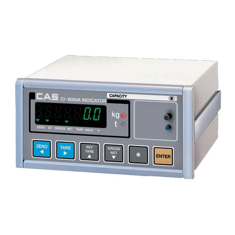
CAS CI-150A User manual

2

3
CONTENTS
PRECAUTIONS .................................................................. 4
INTRODUCTION ............................................................... 6
THE FEATURES OF CI-150A SERIES ........................ 6
TECHNICAL SPECIFICATION .................................... 7
MEASURE OF APPEARANCE ...................................... 9
FRONT PANEL ................................................................. 10
REAR PANEL .................................................................... 12
INSTALLATION & CONNECTION ........................... 13
TEST MODE........................................................................ 14
CALIBRATION MODE.................................................... 17
SET MODE ......................................................................... 25
WEIGHING MODE ......................................................... 47
COMMUNICATION PIN MAP .................................... 53
APPENDIX ......................................................................... 55
ERROR MESSAGE ......................................................... 65

4

5

6
INTRODUCTION
We greatly appreciate your purchase of the CI-150A series weighing indicator.
These goods perform excellently and exhibit splendid properties through strike tests.
CAS indicator (CI-series) is delicately designed to coincide with the special requirements of
several industrial fields and includes many functions and various external interfaces. Also, it is
programmed for the user's convenience and contains help display functions that are easily
accessible.
Before using CI-150A series, it is recommended that you read this manual carefully so you
may use this device to its full potential.
THE FEATURES OF CI-150A SERIES
(1) Features.
■High quality, high accuracy
■Appropriate for weight and measurement system
■Easy operation and various options
■Display of 6 digit(7 segment)
■RFI/EMI screened
■Watchdog circuitry(System restoration).
■Weight back-up(Memory the weight at sudden power failure)
(2) Main Function
■Store date, time and calculated data at sudden power failure
■Adjustable display rate(Digital filter function)
■Tare weight setting with keys
■Users can set maximum weight which users want to and division at one's disposal
■Self test hardware function
■Independent zero calibration
■Serial printer connection
■External input/output (option)
: 2 external input 4 external output(zero, 1 step, 2 step, final)
■Print date and time by inner clock(option)
■Analog out (option)
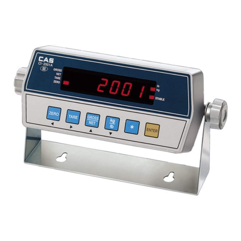
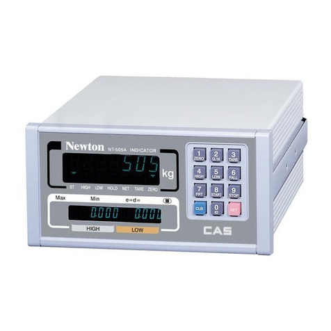
7
TECHNICAL SPECIFICATION
Analog Part & A/D Conversion
Load cell excitation
voltage DC 5 V
Zero adjust range 0.05 mV∼5 mV
0.5 uV/D
Input sensitivity 2 uV/D (CE)
Nonlinearity 0.01 % F.S.
A/D internal resolution 1/1,000,000
A/D external resolution 1/30,000(Max.)
A/D conversion speed 320 times/sec
Digital Part
Span calibration Full Digital Calibration
(Single pass automatic span calibration)
Input noise below ±0.3μVpp
Input impedance over 10MΩ
Display 7 Segment(6 digit)
Maximum capacity 999999
Division ×2, ×5, ×10, ×20, ×50
Display below zero "-" minus signal
Permitted limit tare Full capacity
Key Description
"STABLE" ■LAMP Weight is stable
"TARE" ■LAMP Tare is used
"NET" ■LAMP ON(NET weight), OFF(GROSS weight)
"HOLD" ■LAMP Hold in Weight
"ZERO" ■LAMP "0" kg

8
General Specification
Power DC 9~24 V 1.5 A
Size 110(W)×100(D)×66(H)
Temperature -10℃∼+40℃
Weight Approx 0.4 kg
Power Consumption Approx 2W
Option Part
Option-1 RS-485(Serial)
Option-2 Inner Clock
Option-3 Analog Out
Option-4 Relay (2 Input, 4 Output)

9
MEASURE OF APPEARANCE

10
FRONT PANEL
(1) Display lamp(■)
■ST lamp: turn on when the weight is stable.
■TARE lamp: turn on when tare weight is stored.
■NET lamp: turn on when the current weight is NET weight.
■HOLD lamp: turn on when the weight is held while weighing moving or alive things.
■ZERO lamp: turn on when the current weight is 0 kg.

11
(2) Keyboard
■Used to return the display to the 0.
■User set the zero range within 4% or 10% of the maximum capacity(GEN.09).
■Used to enter the TEST mode.
■Used to weigh item by using the container.
■When this key is pressed, the scale stores current weight as the tare weight.
■If you press TARE key in unload condition, tare setting is released.
■Used to enter the SET mode.
■Use this key to switch from GROSS to NET weight.
■The annunciators and display will alternate between GROSS and NET as well.
■In case tare weight is REGISTERED, tare plus item's weight is GROSS
weight and only item's weight is NET weight.
■When the lamp turning on, it means NET weight.
■Used to enter the CAL mode.
■When you press this key, the current designated printing form is printed.
■Use this key when weighing data is printed.
■Some functions can be defined to the needs.(GEN.19)
■Press and hold SET key to enter the menu mode.

12
REAR PANEL
■POWER S/W : POWER ON/OFF
■LOAD CELL : Port for connecting load cell
1 : EX+ 2 : EX- 3 : SIG+ 4 : SIG- 5 : GND
■DC(POWER) : 9~24V 1.5A
■SERIAL : RS-232C
■SERIAL : RS-485C (option)
■A-OUT : Analog Out port (V-Out : Voltage, I-Out : Current) (option)
■EXT-IO : External input/output port (option)

13
INSTALLATION & CONNECTION
(1) Load Cell Connection
Pin 1: Excitation voltage+
Pin 2: Excitation voltage-
Pin 3: Sense voltage+
Pin 4: Sense voltage-
Pin 5: Shield
■Connecting method
▶Ref. Each L/C
manufacturer'sormodel's
wirecolorcouldbe
different.Inthatcase,
pleasenotethefollowing
diagram.
■Manufacturer's wire colors
Connector
Company Pin 1
(EX+) Pin 2
(EX-) Pin 3
(SIG+) Pin 4
(SIG-) Pin 5
(GND)
CAS RED WHITE GREEN BLUE CASE
KYOWA RED BLACK GREEN WHITE CASE
INTERFACE RED BLACK GREEN WHITE CASE
P.T RED BLACK GREEN WHITE CASE
BLS GREEN BLACK WHITE RED YELLOW
SHOWA RED BLUE WHITE BLACK CASE
SHINKOH RED BLACK GREEN WHITE CASE
TMI RED WHITE GREEN BLUE YELLOW
TML RED BLACK WHITE GREEN CASE
TFAC RED BLUE WHITE BLACK YELLOW
HUNTLEIGH GREEN BLACK RED WHITE CASE
EX+
1
SIG+
SHIELD
SIG
-
EX
-
2
34
5
6
7

1
4
TEST MODE
(1) How to Enter
Turn on the power while pressing the "ZERO" key on the front of the indicator.
※When test is done, Press SET key.
(2) Available Keys
Set key: Used for moving to the next test menu.
Other keys: Used for changing the preset value.
(3) Test Menu(TEST 1 - TEST 8)
TEST 1 : Key test
TEST 2 : Display test
TEST 3 : Load cell test and A/D conversion test
TEST 4 : Serial interface test
TEST 5 : Printer test
TEST 6 : A-out test(OPTION)
TEST 7 : External input/output test(OPTION)
TEST 8 : RTC test(OPTION)
TEST 1
FUNCTION : Key test
KEY DISPLAY DESCRIPTION
SET key : next menu
Other keys: Perform
test
Key number
ex) In case of
Zerokey1
Press the key to be test and the No of
key mode should identify with code of
key as the follows.
If you press Set key, it will be moved to
test 2.
<Key List>
Key name No
ZERO 1
TARE, ◀2
N/G, ▲3
PRINT, ▼4
SET 5

15
TEST 2
FUNCTION : Display test
KEY DISPLAY DESCRIPTION
SET key : next menu TEST 2 is performed.
If you press Set key, it will be moved to
test 3
TEST 3
FUNCTION : A/D converter test
KEY DISPLAY DESCRIPTION
ZERO key: Cancel
SET key : next menu
Display digital value
of current weight.
ex)
Display digital value of current weight.
This value means converted digital value
under actual condition.
If you press Set key, it will be moved to
test 4.
►Note 1. Check whether digital value is changing.
If the digital value is fixed or zero is displayed, please check the connection
ofloadcell.
TEST 4
FUNCTION : RS-232, RS-485 test with computer(Serial port)
KEY DISPLAY DESCRIPTION
▲ Key : Value change
ZERO key: Cancel
SET key : next menu
Waiting for transmission and reception
Received: none, Transmitted : 1
►Note 1. Do this test after the connection of serial port of computer and serial port of
indicator is done.
Note 2. Send no.1 in computer keyboard and check if indicator receives no.1
Send no.1 in indicator keyboard and check if computer receives no.1
Note 3. Do this test after baud rate is specified in SET mode (RS-232 : F2-03 and
RS-485 : F2-08).

16
TEST 5
FUNCTION : Printer test(PRINTER)
KEY DISPLAY DESCRIPTION
SET key : next menu
No error in printer.
Do this test after connection serial printer.
TEST 6 (OPTION)
FUNCTION : A-OUT test
KEY DISPLAY DESCRIPTION
▲Key : Value change
ZERO key : Cancel
SET key : next menu 25 P
The output level of Aout is raised by 25%
each time the ▲ key is pushed.
TEST 7 (OPTION)
FUNCTION : External Input / Output test
KEY DISPLAY DESCRIPTION
▲Key : Value change
ZERO key : Cancel
SET key : next menu
I - X O - X
----------
I - 2 O – 4
Displayed in the external input section
when there is an external input.
Push ▲key to execute weighing
external output
input : 2, output : 4
TEST 8 (OPTION)
FUNCTION : RTC test
KEY DISPLAY DESCRIPTION
SET key : next menu SEC XX XX : Displaying the progress of seconds
(SEC)

17
CALIBRATION MODE
(1) How to Enter
Turn on the power while pressing “NET/GROSS” key on the front of the indicator.
(2) Calibration Menu(CAL 1 - CAL 9)
CAL 1: Maximum capacity set
CAL 2: Minimum division set
CAL 3: Zero & Span calibration
CAL 5: Direct calibration
CAL 6: Zero adjustment
CAL 7: Factor calibration
CAL 8: Gravity adjustment
CAL 9: Setting dual range
CAL 1
CAL 1-1
FUNCTION : Set Unit
Set Unit : kg, ton
KEY DISPLAY DESCRIPTION
kg Unit : kg
▲, ▼Key : Value change
ZERO Key : Cancel
SET Key : Save and next menu ton Unit : ton

18
CAL 1-2
FUNCTION : Setting Maximum Value
Range of set value : 1 ~ 99,999
KEY DISPLAY DESCRIPTION
▲Key : Value change
◀Key : Digit change
ZERO Key : Cancel
SET Key : Save and next menu
Max value = 5000 kg
Max value = 20000 kg
►Note 1. It means the maximum weight value to be weighed by the scale.
CAL 2
FUNCTION : Minimum division and decimal position setting
Range of set value : 0.001 ~ 50
KEY DISPLAY DESCRIPTION
▲, ▼Key : Value change
ZERO Key : Cancel
SET Key : Save and next menu
1 kg
0.2 kg
0.05 kg
0.001 kg
►Note 1. To end CAL2, press CANCEL key when a decimal point is set.
Note 2. Set the external resolution within 1/30,000 as the value by dividing the maximum
weight by the minimum division.
If the external resolution is 1/30,000 or more, Err 21 is shown.
Note 3. The position of a decimal point is decided by the position of a decimal point for the
minimum division set in CAL2.

19
CAL 3
CAL 3-1
Function : Setting Multi Calibration Step
Range of set value : 1 ~ 5
KEY DISPLAY DESCRIPTION
STEP- 1 Setting multi calibration for step 1
(CAL3-3 and CAL 3-4 are carried out once)
▲, ▼Key : Value change
ZERO Key : Cancel
SET Key : Save and next
menu STEP- 5 Setting multi calibration for step 5
(CAL3-3 and CAL3-4 are carried out five times.)
►Note 1. A function to use, when the output of load cell is corrected by setting multiple
points in some sections because the actual curve of load cell is not a straight line.
(zero span)
Zero and Span points to interpolate weight from Load Cell
Multi-point
Multi-point
mV/V
Real curve
weight
(full span)
Multi-point
Ideal
Multi-point
Multi-point
CAL 3-2
Function: Zero Calibration
KEY DISPLAY DESCRIPTION
UnLoAd Empty the load tray and press the setup key.
1234 The current weight value is displayed.
Confirm 'Stable' and press the setup key.
ZERO Key : Cancel
SET Key : Save and next
menu
- - - Zeroing in progress...
►Note 1. If zeroing finished with no error, it moves to Setting Weight (CAL 3-3) although
nokeyispressed.

20
CAL 3-3
Function: Setting Weight
Range of set value: 1 ~ 99,999
KEY DISPLAY DESCRIPTION
LOAD 1 It means the weight setting mode.
(Number = multi calibration number)
W=100.00 100.00 (unit: Kg or Ton)
▲Key : Value change
◀Key : Digit change
ZERO Key : Cancel
SET Key : Save and next
menu
W= 0.10 0.10 (unit: Kg or Ton)
►Note 1. Set the weight within a range of 10% ~ 100%.
CAL 3-4
Function: Weight Calibration
KEY DISPLAY DESCRIPTION
LoAd Load the weight set in CAL 3-3 and press the
setup key.
12345 The current weight value is displayed.
Confirm 'Stable' and press the setup key.
ZERO Key : Cancel
SET Key : Save and next
menu
- - - Span adjustment in progress...
►Note 1. CAL 3-3 and CAL 3-4 are repeated as many as STEP is set in CAL 3-1.
At this time, the weight value should be set to a value greater than the previous one.
Note 2. Move to CAL-3 if the span adjustment is over with no error.

21
CAL 5 (Direct Calibration)
CAL 5-1
Function: Direct input about the zero value of loadcell
Range of set value: 1 ~ 99,999
KEY DISPLAY DESCRIPTION
ZE-CAL Direct zero input mode
0.0000 Loadcell zero = 0.0000 mV/V
▲Key : Value change
◀Key : Digit change
ZERO Key : Cancel
SET Key : Save and next
menu
0.1000 Loadcell zero = 0.1000 mV/V
CAL 5-2
Function: Direct input about the span value of loadcell
Range of set value: 1 ~ 99,999
KEY DISPLAY DESCRIPTION
SP-CAL Direct span input mode
1.2000 Loadcell span = 1.2000 mV/V
▲Key : Value change
◀Key : Digit change
ZERO Key : Cancel
SET Key : Save and next
menu
2.0000 Loadcell span = 2.0000 mV/V
Table of contents
Other CAS Accessories manuals

CAS
CAS RW Series User manual

CAS
CAS CI-2001A User manual

CAS
CAS CI-2001AS User manual

CAS
CAS EXP-2000A User manual

CAS
CAS CI-2400BS User manual

CAS
CAS NT-500 Series User manual

CAS
CAS CI-502A User manual

CAS
CAS WEIGHING SOLUTION NT-200 Series User manual

CAS
CAS CI-170A User manual

CAS
CAS SW II Series User manual
Popular Accessories manuals by other brands

Libelium
Libelium Waspmote Plug & Sense! Series user manual

Philips
Philips 22285-1 Specifications

Novital
Novital Covatutto 16L user manual

Transcell Technology
Transcell Technology TI-1520 user manual

EFBE-SCHOTT
EFBE-SCHOTT IR 801 operating instructions

Woan Technology
Woan Technology SwitchBot W1101500 user manual