TE Connectivity LGA1366 User manual

TE connectivity Confidential
This communication includes TE connectivity confidential or
proprietary information that may also be legally privileged.
28 Apr ‘11 Rev.C
411-78289
Instruction Sheet
Lever Actuated Land Grid Array
LGA1366 / LGA1356 Socket
1 of 31
LGA1366 / LGA1356 is designed to
receive the 1366 / 1356 position LGA
package. Read this instructions thoroughly
before installing the package onto the
socket. This sheet covers the instruction
from after SMT through package
installation.
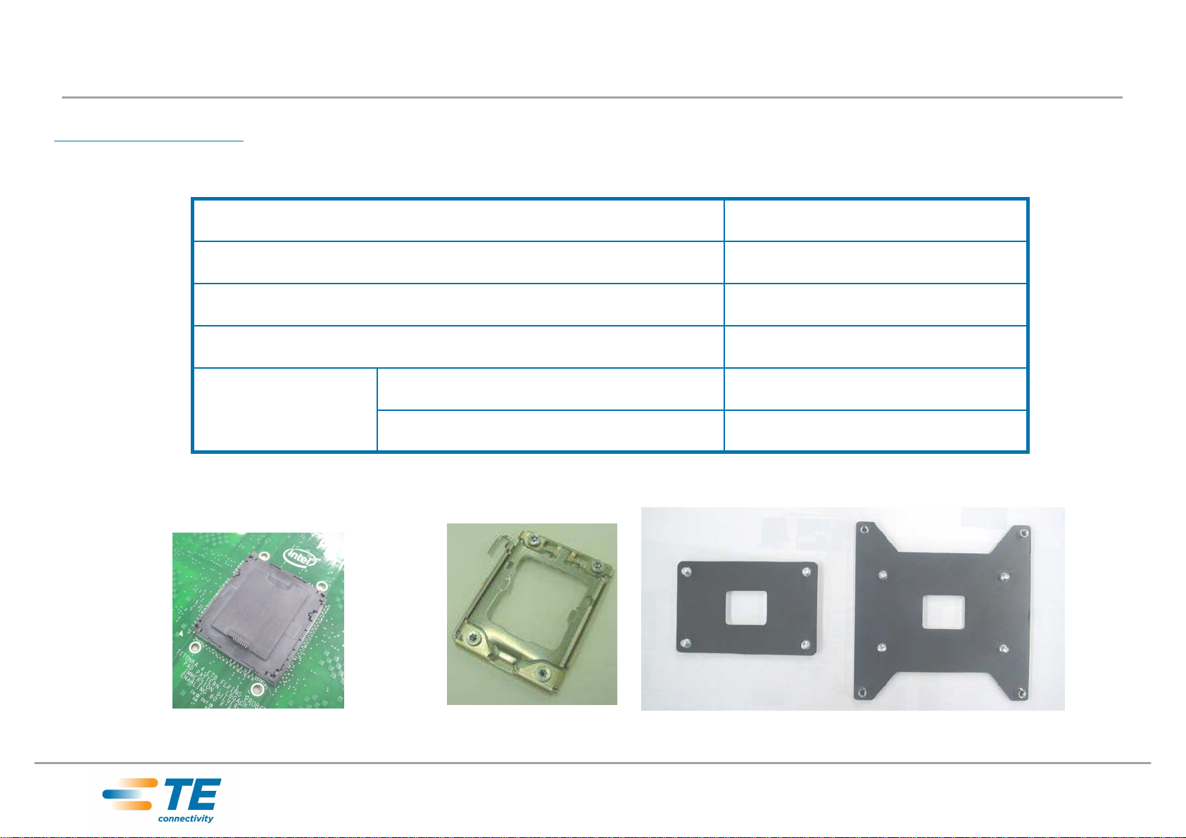
Tyco provides three components for
LGA1366 / LGA1356 socket system, ILM
cover assembly (Fig 2a), socket (Fig2b),
and back plate (Fig2c).
These components shall be used correctly
to secure electrical and mechanical quality.
Fig.1 System of LGA1366 / LGA1356 socket
ILM cover
assembly
1. Introduction
LGA1366 /
LGA1356
Socket
Back plate

TE connectivity Confidential
This communication includes TE connectivity confidential or
proprietary information that may also be legally privileged.
28 Apr ‘11 Rev.C
411-78289
Instruction Sheet
Lever Actuated Land Grid Array
LGA1366 / LGA1356 Socket
2 of 31
Fig.2c Back plate
(A) Fig.2d Back plate
(B)
Fig.2a LGA1366 / LGA1356
socket with PnP cap (on PCB) Fig.2b ILM cover
assembly
X-1554116-X (*1)
2) LGA1356 Socket
Type (B) -Server back plate
Type (A) -Desk top back plate
X-1981467-X (*1)
X-1939739-X (*1)
4) Back plate
(*2)
X-1939738-X (*1)
3) ILM cover assy
X-1981837-X (*1)
1) LGA1366 Socket
Part Number
Description
(*1) refer to customer drawing for detail
(*2) Type of back plate is selected by customer’s board design
In this document, “Back plate” is used as standard name
2. Components
Components are changed by system design and combination of three components is required.

TE connectivity Confidential
This communication includes TE connectivity confidential or
proprietary information that may also be legally privileged.
28 Apr ‘11 Rev.C
411-78289
Instruction Sheet
Lever Actuated Land Grid Array
LGA1366 / LGA1356 Socket
3 of 31
Fig.3 LGA1366 / LGA1356
socket with PnP cap on PCB Fig.4 LGA1366 / LGA1356
socket without PnP cap
Contacts
PnP cap
Housing
Orientation key for
processor
3. Description of each components
3.1 LGA1366 / LGA1356 socket
Contact grid area
Orientation key for ILM
cover assembly
Tab for finger
access
Notch for finger
access
Pin1 indicator

TE connectivity Confidential
This communication includes TE connectivity confidential or
proprietary information that may also be legally privileged.
28 Apr ‘11 Rev.C
411-78289
Instruction Sheet
Lever Actuated Land Grid Array
LGA1366 / LGA1356 Socket
4 of 31
Lever
Frame
Load plate
Nut (4pcs )
Fig.5 ILM cover assembly (case of U shape lever)
Hook for lever
Pin1 indicator
Tail tab
Load plate
tab(*1)
3. Description of each components
3.2 ILM cover assembly
*1) Load plate tab is on lever in shipping status for easier assembly

TE connectivity Confidential
This communication includes TE connectivity confidential or
proprietary information that may also be legally privileged.
28 Apr ‘11 Rev.C
411-78289
Instruction Sheet
Lever Actuated Land Grid Array
LGA1366 / LGA1356 Socket
5 of 31
Fig.8 Server back plate (B)Fig.6 Desktop back plate (A)
Stud bolt for ILM nut
(4pcs)
Female nut for
heat sink (4pcs)
Fig.7 Stud bolt
Insulator
sheet
Top view
Bottom view Bottom view
Top view
3. Description of each components
3.3 Back plate

TE connectivity Confidential
This communication includes TE connectivity confidential or
proprietary information that may also be legally privileged.
28 Apr ‘11 Rev.C
411-78289
Instruction Sheet
Lever Actuated Land Grid Array
LGA1366 / LGA1356 Socket
6 of 31
Three components shown below are used in this document.
For SMT’d socket, please refer 114-5432, application specification for SMT process
onto PCB.
Fig.9 LGA1366 / LGA1356
socket on PCB Fig.10 ILM cover assembly Fig.11 Server back plate
4. ILM cover assembly and back plate assembly procedure
4.1 Prepare components

TE connectivity Confidential
This communication includes TE connectivity confidential or
proprietary information that may also be legally privileged.
28 Apr ‘11 Rev.C
411-78289
Instruction Sheet
Lever Actuated Land Grid Array
LGA1366 / LGA1356 Socket
7 of 31
Fig.12 Fig.14
Fig.13
Attach back plate to PCB from back side. 4 stud bolts go through applicable 4 holes
of PCB. (Fig.12)
There should be no clearance between PCB and back plate (Fig.14)
Please confirm if there are any foreign object or irregular warpage of PCB
There should be no
clearance between
PCB and back plate
4. ILM cover assembly and back plate assembly procedure
4.2 Assemble back plate on PCB

TE connectivity Confidential
This communication includes TE connectivity confidential or
proprietary information that may also be legally privileged.
28 Apr ‘11 Rev.C
411-78289
Instruction Sheet
Lever Actuated Land Grid Array
LGA1366 / LGA1356 Socket
8 of 31
Fig.17
Fig.16
Grasp the ILM cover assembly north side and south side as shown in Fig 15
Then put it onto PCB confirming the orientation by pin1 indicator.
Pin1 indicator
Pin1 indicator on
PnP cap is under
load plate
4. ILM cover assembly and back plate assembly procedure
4.3 Attach ILM cover assembly
North
South
Fig.15

TE connectivity Confidential
This communication includes TE connectivity confidential or
proprietary information that may also be legally privileged.
28 Apr ‘11 Rev.C
411-78289
Instruction Sheet
Lever Actuated Land Grid Array
LGA1366 / LGA1356 Socket
9 of 31
Fig.19
4. ILM cover assembly and back plate assembly procedure
4.3 Attach ILM cover assembly (Cont’d)
Fig.18
CAUTION
Please don’t open load plate before assembly to PCB.
Load plate cannot be closed due to load plate
hitting the nut pushed up by the studs
Load plate

TE connectivity Confidential
This communication includes TE connectivity confidential or
proprietary information that may also be legally privileged.
28 Apr ‘11 Rev.C
411-78289
Instruction Sheet
Lever Actuated Land Grid Array
LGA1366 / LGA1356 Socket
10 of 31
Fig.21
4. ILM cover assembly and back plate assembly procedure
4.3 Attach ILM cover assembly (Cont’d)
All of the nuts of ILM cover assembly are
pushed up by the studs if placed in correct
orientation. (Fig.20)
OK
Nut is pushed up
by stud
OK
All nuts are pushed
up by stud
NG
Nuts are pushed
up by stud
Float from PCB
Non clearance between
nut and frame
Case of incorrect
orientation
NG
Non clearance
between nut and frame
ILM has large gap to PCB
Fig.20

TE connectivity Confidential
This communication includes TE connectivity confidential or
proprietary information that may also be legally privileged.
28 Apr ‘11 Rev.C
411-78289
Instruction Sheet
Lever Actuated Land Grid Array
LGA1366 / LGA1356 Socket
11 of 31
No.1
No.3
No.4
No.2
Fasten ILM nuts using TORX driver.
Fastening order is shown in Fig.22
- Driver size: T-20
- Torque: 8 to 10 in-lbf (0.9 to 1.1 Nm)
After fastening all of 4 nuts, confirm there is no clearance between collar and PCB (Fig.23)
And confirm the frame moves free in Z direction at lever open condition.
(Fig.24)
Fig.23Fig.22
North side view
Fig.24
4. ILM cover assembly and back plate assembly procedure
4.4 Fastening ILM nuts
Frame can move freely in Z
direction in the clearance
Collar
Confirm if there
isn’t clearance
North
East
East side view
Frame is on PCB

TE connectivity Confidential
This communication includes TE connectivity confidential or
proprietary information that may also be legally privileged.
28 Apr ‘11 Rev.C
411-78289
Instruction Sheet
Lever Actuated Land Grid Array
LGA1366 / LGA1356 Socket
12 of 31
Fig.25 Completion ILM cover
assembly and back plate
assembly
4. ILM cover assembly and back plate assembly procedure
4.5 Completion

TE connectivity Confidential
This communication includes TE connectivity confidential or
proprietary information that may also be legally privileged.
28 Apr ‘11 Rev.C
411-78289
Instruction Sheet
Lever Actuated Land Grid Array
LGA1366 / LGA1356 Socket
13 of 31
5. Package installation procedure
5.1 Open load plate
To open the load plate, push its tail then the tab side will be lifted up. (Fig.26, 27)
Remove the lever from hook then rotate it until it stops. (Fig.28, 29)
Fig.26
Fig.27 Fig.29
Fig.28
Push
Lift up
Fig.30 Load plate OPEN position

TE connectivity Confidential
This communication includes TE connectivity confidential or
proprietary information that may also be legally privileged.
28 Apr ‘11 Rev.C
411-78289
Instruction Sheet
Lever Actuated Land Grid Array
LGA1366 / LGA1356 Socket
14 of 31
Fig.32 Grasp PnP cap and
pull straight up
Fig.31 Tabs for removal Fig.33 After PnP cap
removal
5. Package installation procedure
5.2 Remove PnP cap
The PnP cap has two tabs for removal. (Fig.31)
Remove PnP Cap by grasping the 2 tabs and pull it straight up. (Fig.32)
After the PnP cap is removed, contacts are exposed. (Fig.33)
CAUTION
DO NOT TOUCH THE CONTACT

TE connectivity Confidential
This communication includes TE connectivity confidential or
proprietary information that may also be legally privileged.
28 Apr ‘11 Rev.C
411-78289
Instruction Sheet
Lever Actuated Land Grid Array
LGA1366 / LGA1356 Socket
15 of 31
NG NG
CAUTION
Please do not open the cap using only 1 of the tabs. (Fig.34, 35)
It may break the cap, or the removed cap may fall in socket contact grid and
damage the contacts.
Fig.34 Fig.35
5. Package installation procedure
5.2 Remove PnP cap (Cont’d)

TE connectivity Confidential
This communication includes TE connectivity confidential or
proprietary information that may also be legally privileged.
28 Apr ‘11 Rev.C
411-78289
Instruction Sheet
Lever Actuated Land Grid Array
LGA1366 / LGA1356 Socket
16 of 31
Fig.37 Pin1 indicator for
ILM cover assembly
Fig.36 Pin1 indicator for
package
5. Package installation procedure
5.3 Package installation – Confirm orientation
Before installation of the package, please confirm the orientation using the Pin1
indicator. (Fig.36,37)

TE connectivity Confidential
This communication includes TE connectivity confidential or
proprietary information that may also be legally privileged.
28 Apr ‘11 Rev.C
411-78289
Instruction Sheet
Lever Actuated Land Grid Array
LGA1366 / LGA1356 Socket
17 of 31
Grasp the package with your thumb and forefinger at median of its edges. (Fig.38)
Place the package onto the contact grid of socket horizontally. (Fig.39, 40)
Please ensure the package is not sitting on the housing of socket. Please see following
slide for prohibitions.
After installation, please confirm if the package is installed correctly. (Fig.41)
Check 4 corners - the housing walls guide the package
Check orientation keys are aligned with the package cut outs
Fig.38 Grasp
package Fig.39 Verify
orientation
Pin1 indicator
Fig.40 Horizontal
instillation Fig.41 Confirm package
installed correctly
5. Package installation procedure
5.3 Package installation – How to hold the package

TE connectivity Confidential
This communication includes TE connectivity confidential or
proprietary information that may also be legally privileged.
28 Apr ‘11 Rev.C
411-78289
Instruction Sheet
Lever Actuated Land Grid Array
LGA1366 / LGA1356 Socket
18 of 31
Do not place the package in as offset position and do not slide the package on the
contact grid (Fig.42), to prevent damaging contacts.
Do not begin lever actuation if the package is in offset condition.(Fig.43)
Fig.42
NG
5. Package installation procedure
5.3 Package installation – Cautions
CAUTION
Fig.43
NG

TE connectivity Confidential
This communication includes TE connectivity confidential or
proprietary information that may also be legally privileged.
28 Apr ‘11 Rev.C
411-78289
Instruction Sheet
Lever Actuated Land Grid Array
LGA1366 / LGA1356 Socket
19 of 31
Fig.45
Fig.44
If package is placed incorrectly, (Fig.45, 46), please remove it carefully to avoid
damage to contacts.
Housing
cavity
4 corners
of housing
cavity
Alignment key
Fig.46
NG
NG
5. Package installation procedure
5.3 Package installation – If Package is placed incorrectly

TE connectivity Confidential
This communication includes TE connectivity confidential or
proprietary information that may also be legally privileged.
28 Apr ‘11 Rev.C
411-78289
Instruction Sheet
Lever Actuated Land Grid Array
LGA1366 / LGA1356 Socket
20 of 31
Fig.48 Operate lever to
hook
Fig.47 Rotate down
the load plate
5. Package installation procedure
5.3 Package installation – Close load plate
Fig.49 Confirm the lever has
engaged the load plate tab
Rotate the load plate slowly while grasping its tab. (Fig.47)
Gently push the load plate tab side and close the lever slowly. (Fig.48)
Please confirm if the lever has engaged the load plate tab. (Fig.49) If lever does not
engage the tab, please confirm the CPU package is installed correctly. (Fig.41)
Push gently
This manual suits for next models
1
Table of contents
Other TE Connectivity Accessories manuals
Popular Accessories manuals by other brands

Assault Fitness
Assault Fitness Airbike Elite TECHNICAL SPECIFICATIONS & USE GUIDELINES

Airmar Technology Corporation
Airmar Technology Corporation S69 Owner's guide and installation instructions

Perenio
Perenio PECWS01 quick start guide

Qimarox
Qimarox PRORUNNER Mk5 user manual

Stulz Tecnivel
Stulz Tecnivel EV installation guide

DayStar Filters
DayStar Filters CALCIUM QUARK manual