idronaut Ocean Seven 316 Plus CTD User manual

OCEAN SEVEN 316Plus CTD
Multiparameter Probe
OPERATOR'S MANUAL
Copyright @ 1982 –2018 Idronaut S.r.l. All rights reserved.
OCEAN SEVEN and Idronaut are registered trademarks of Idronaut S.r.l.
Other products and services mentioned in this document are identified by the trademarks or service marks of their respective companies
or organisations. No part of this publication, or any software included with it, may be reproduced, stored in a retrieval system, or
transmitted in any form or by any means, including photocopying, electronic, mechanical, recording or otherwise, without the prior
written permission of the copyright holder. Idronaut S.r.l. provides this document as is without warranty of any kind either expressed or
implied including, but not limited to, the implied warranties of merchantability and fitness for a particular purpose. Idronaut S.r.l. may
make changes of improvements in the equipment, software, firmware, or specifications described in this document at any time and
without notice. These changes may be incorporated in new releases of this document. This document may contain technical inaccuracies
or typographical errors. Idronaut S.r.l. waives responsibility of any labour, materials, or costs incurred by any person or party as a result
of using this document. Idronaut S.r.l. shall not be liable for any damages (including, but not limited to, consequential, indirect or
incidental, special damages, or loss of profits or data) even if they were foreseeable and Idronaut S.r.l. has been informed of their potential
occurrence arising out of or in connection with this document or its use.

IDRONAUT –Brugherio (MB) OCEAN SEVEN 316Plus PROBE 03-2018
OCEAN SEVEN 316Plus CTD
IMPORTANT REMARKS
ON/OFF SOUND ALERT
The Ocean Seven 316Plus CTD is equipped with a “buzzer” which, at the probe start-up,
alerts/advises the operator on the undertaken operations.
The following codes are defined in the present software:
1 pulse : probe wakes up waiting for operator’s commands;
2 pulses : unattended linear profile in function of pressure increments starts;
3 pulses : unattended timed data acquisition operation starts.
4 pulses : unattended continuous data acquisition operation starts.
6 pulses : remote unattended monitoring operation starts.
INTERNAL BATTERY REPLACEMENT/RECHARGING
1) To gain access to the battery pack, remove the screws in the probe top cover. However,
before doing this, please ensure to have removed any water droplets around the screw
heads, to prevent them from running down inside the housing.
2) Rechargeable battery: disconnect the battery pack from the top cover and connect it
to the external battery charger.
3) If the probe is not to be used for long periods (some months), remove the internal
battery pack from the probe. This eliminates the possibility of damaging the electronic
circuitry in case of battery leakage.
4) Do not leave the probe “magnetic rotary switch” in the ON position when the probe is
not in use because a small amount of energy is drawn from the internal batteries by
the probe electronic circuitry. This phenomenon causes batteries to run down and they
may be damaged in a very long time. ALWAYS ROTATE THE SWITCH TO THE
OFF POSITION WHEN THE CTD IS NOT IN USE.
SELF-RECORDING USE
The probe is equipped with a rotary magnetic power ON/OFF switch, present on the top
cover. The probe is ON when the switching arm is over the dot marker to achieve self-
recording data acquisitions, as described in the dedicated section of this manual. Once the
self-recording configuration of the probe has been set, the probe can be switched OFF and
then ON again at the sampling site, when it is ready for deployment.
VERY IMPORTANT: Allow a 30-second interval between each ON/OFF cycle.

IDRONAUT –Brugherio (MB) OCEAN SEVEN 316Plus PROBE 03-2018
CONDUCTIVITY MEASUREMENT
1) To obtain the best accuracy, the conductivity sensor and therefore the probe sensor
head, must be immersed in clean seawater for at least 15 minutes before measurements.
For fresh water application, the sensor does not require any hydration.
2) When the conductivity sensor is not in use, it is kept dry. Therefore, when the
conductivity sensor is placed in water, very small bubbles may remain attached to the
platinum ring electrodes (seven). If such a thing happens, the measured value of
conductivity will be lower than the true one. To remove these air bubbles, degrease
the inside of the conductivity cell using cotton buds wetted with the Conductivity
Sensor Cleaning Solution or with liquid soap. Gently rotate the cotton bud against the
whole internal surface of the quartz cell. This will wet the platinum electrodes, thus
reducing the surface tension of the cell and considerably decreasing the risk of trapped
air bubbles.
OXYGEN MEASUREMENT
Most polarographic oxygen sensors take 5 to 10 minutes after they have been switched on
to polarize and become stable. To overcome this limitation, the IDRONAUT OS316Plus has
been fitted with a small internal rechargeable battery, to maintain polarization of the oxygen
sensor continuously. However, if the probe is not used for several months, the polarization
battery may become completely discharged resulting in damage to the battery. It is
recommended that the probe should be switched ON (and streaming real-time data) for at
least a few hours every 2 to 3 months, to maintain this polarization battery in a healthy
condition.
BLUE CAP OPTICAL DISSOLVED OXYGEN SENSOR
A black cap is provided to protect the membrane from light. When the CTD is not used
protect the membrane by installing the black cap.PLEASE remove the black cap before
calibration and before deploying the CTD in water.
pH MEASUREMENT
The pH and reference sensors should never be allowed to completely dry out. For short-
term storage of up to one day, the probe’s sensor head can simply be immersed in clean
water. If the probe remains unused for periods longer than one day, always place the
hydrating caps on both sensors. The pH sensor cap should be filled with the pH7 Buffer
Solution (or simply with clean water). The reference sensor cap should be filled with the
Idronaut Reference Sensor Storage Solution (or even with KCl saturated solution).
PROBE WASHING
After use, the probe must be always washed with fresh water in order to remove any salt
water residual or dirtiness.
LIFETIME AND HOW TO REPLACE THE IDRONAUT SENSORS
The IDRONAUT sensors are all pressure compensated and, in particular, the physical
sensors (pressure, temperature and conductivity) can last many years, if properly used.
They are high-quality sensors, as they are well known by oceanographers to measure
salinity with great accuracy.
If thoroughly maintained by their respective hydrating caps and solutions, the IDRONAUT
pH and reference sensors can last several years. The sensor replacement requires that the
closure screws on the top head of the probe be unscrewed with a common screwdriver and
the cylindrical housing be removed (this takes very few minutes). The wire sensors are tin
soldered on their respective connection points placed on the printed circuit board. All sensor
heads have a standard 12 mm diameter and are provided with two o-rings (Parker 12-2) for

IDRONAUT –Brugherio (MB) OCEAN SEVEN 316Plus PROBE 03-2018
sealing. This means that every sensor can be fitted in any of the five sensor head holes. The
pressure sensor is a high-quality transducer, which lasts many years if properly used. Its
replacement is not very easy and, moreover, it requires a Dead Weight Tester System to
obtain the factory calibration accuracy of 0.05% full scale.
COPYRIGHT STATEMENT
Copyright IDRONAUT S.r.l.
OCEAN SEVEN and IDRONAUT are registered trademarks of IDRONAUT S.r.l. All rights reserved.
This document may not, in whole or in part, be copied, photocopied, reproduced, translated, or reduced to
any electronic medium or machine-readable form without prior consent in writing from IDRONAUT S.r.l.
ABOUT THIS MANUAL
This manual will serve as a guide to you when you use the OCEAN SEVEN 316Plus probes.
❖Use it to understand the purpose of each of the probe components and functions.
❖It will help you to understand the probe behaviour.
❖It will guide you through the probe capabilities.
❖It will serve you as a reference when some problems arise when using the probe.
HOW TO USE THIS MANUAL
The following topics are covered by this manual:
Section 1 A description of the OCEAN SEVEN 316Plus probe.
Section 2 Installation and start-up operations.
Section 3 Data acquisition functions and data processing capabilities.
Section 4 Data storage functions.
Section 5 Sensor calibration functions.
Section 6 Service functions (configuration, diagnostics).
Section 7 Probe maintenance.
Section 8 Troubleshooting
Appendix A Internal and external battery pack description.
Appendix B Data Processing Function Priming.
Appendix C Highly precise pressure transducer
Appendix D Advanced configuration and telemetry.
Appendix E GENERAL OCEANICS Rosette interfacing.
Appendix F IDRONAUT Windows Terminal Emulation Programme.
Appendix G Antifouling device.
Appendix H Conductivity with Integrated UV-LED Antifouling.
Appendix I Wireless “Bluetooth™” Interface.
Appendix J Submersible connectors and cable care.
Appendix K Sensor cleaning and care.
Appendix L String and weight bottom sensor.
Appendix M CT sensor pair forced flow.
Appendix N BLUE CAP optical dissolved oxygen sensor.
GETTING STARTED
To become familiar with the OCEAN SEVEN 316Plus probe capabilities and operation, we suggest reading
through sections 1 and 2. It is necessary to also read sections 3 and 5 and section 7 before starting to deploy
the probe . The remaining sections and appendices could be consulted only when needed. If the probe is
supplied with external sensors, , deck unit or the Idronaut Portable Reader, useful information can be found
in each dedicated Operator’s Manual.
Operator’s Manuals of all IDRONAUT products and software can be found on the CD-ROM included with

IDRONAUT –Brugherio (MB) OCEAN SEVEN 316Plus PROBE 03-2018
this product in the “Literature & Manuals\Operator Manual”folder.
NOTATIONAL CONVENTIONS
Throughout this manual, the following conventions are used to distinguish the various elements of the text:
[PROBE COMMANDS] They always appear in uppercase and between [ ] or < > brackets.
Probe messages, user inputs They always appear in italics.
DEFINITION OF TERMS
Throughout this manual, the following terms are used:
Cast As a whole of the data set collected in the same way in a determined
sampling point.
Data set As a whole of configured parameters expressed in physical or
chemical units and acquisition date and time, collected at
programmed sampling interval, (i.e. once per second, once per
depth increment).
Raw data –ADC Counts As a whole set of data acquired by means of the ADC and the
conditioning circuits, from the configured sensors and are
expressed in numeric decimal or hexadecimal format.
Non-verbose mode This term refers to a probe that has been configured to use a
communication protocol (computer oriented) to communicate with
the operator.
Verbose mode This term refers to a probe that has been configured to use the MMI
functions to communicate with the operator.
ON condition This term refers to a fully operative probe, waiting for commands
from the operator or running the requested command.
OFF condition This term refers to a probe electronically switched off. In this state,
the probe draws negligible amount of current from the battery.
MMI This term refers to the set of common rules, which the operator must
follow during the operation of probe in verbose mode.
FSK Frequency Shift Keying.
QAM Quadrature Amplitude Modulation.
IDRONAUT DOCUMENTS PERTAINING TO THE OCEAN SEVEN 316Plus
The following documents are available in the “Literature & Manual” folder on the CD-ROM distributed with
the OCEAN SEVEN 316Plus CTD.
❖OCEAN SEVEN Probes Data Transmission Protocol Description.
❖IDRONAUT Deck Unit Operator’s & Installation manual.
❖REDAS-5 Condensed Manual.
❖OCEAN SEVEN Portable Reader Operator’s Manual.
SOFTWARE UPDATES AND TECHNICAL SUPPORT
Please visit our website download area for software updates and technical support: http://www.idronaut.it
WARRANTY
The OCEAN SEVEN 316Plus probe is covered by a one-year limited warranty that extends to all parts and
labour and covers any malfunction that is due to poor workmanship or due to errors in the manufacturing
process. The warranty does not cover shortcomings that are due to the design, nor does it cover any form of
consequential damage because of errors in the measurements. If there is a problem with your OCEAN SEVEN
316Plus, first try to identify the problem by following the procedure outlined in the troubleshooting section
of this manual. Please contact your representative or IDRONAUT Sr.l. if the problem is identified as a
hardware problem or if you need additional help in identifying the problem. Please make sure to contact
IDRONAUT S.r.l. to obtain the relevant instructions before the OCEAN SEVEN 316Plus or any module is
returned to IDRONAUT (see cleaning instructions).

IDRONAUT –Brugherio (MB) OCEAN SEVEN 316Plus PROBE 03-2018
For systems under warranty, IDRONAUT S.r.l. will attempt to ship replacement parts before the
malfunctioning part is returned. We encourage you to contact us immediately if a problem is detected and we
will do our best to minimize the downtime. Every effort has been made to ensure the accuracy of this manual.
However, IDRONAUT S.r.l.makes no warranties with respect to this documentation and disclaims any
implied warranties of merchantability and fitness for a particular purpose. IDRONAUT S.r.l.shall not be liable
for any errors or for incidental or consequential damages in connection with the furnishing, performance or
use of this manual or the examples herein. The information in this document is subject to change without
notice.
CLEANING INSTRUCTIONS
Before the returned OCEAN SEVEN 316Plus can be serviced, equipment exposed to biological, radioactive,
or toxic materials must be cleaned and disinfected. Biological contamination is presumed for any instrument,
probe, or other device that has been used with wastewater. Radioactive contamination is presumed for any
instrument, probe or other device that has been used near any radioactive source. If an OCEAN SEVEN
316Plus probe, or other part is returned for service without following the cleaning instructions, and if in our
opinion it represents a potential biological or radioactive hazard, our service personnel reserve the right to
withhold service until appropriate cleaning, decontamination has been completed.
When service is required, either at the user's facility or at IDRONAUT, the following steps must be taken to
insure the safety of our service personnel.
➢In a manner appropriate to each device, decontaminate all exposed surfaces, including any containers.
70% isopropyl alcohol or a solution of 1/4 cup bleach to 1-gallon tap water are suitable for most
disinfecting. Instruments used with wastewater may be disinfected with 5% Lysol if this is more
convenient to the user.
➢The user shall take normal precautions to prevent radioactive contamination and must use
appropriate decontamination procedures should exposure occur. If exposure has occurred, the
customer must certify that decontamination has been accomplished and that no radioactivity is
detectable by survey equipment.
➢Any product being returned to the IDRONAUT S.r.l. laboratory for service or repair should be packed
securely to prevent damage.
➢Cleaning must be completed on any product before returning it to IDRONAUT S.r.l.
DISPOSAL OF WASTE EQUIPMENT BY USERS IN THE EUROPEAN UNION
The recycling bin symbol on the product or on its packaging indicates that this product must not be disposed
of with your other waste. It is your responsibility to dispose of your waste equipment by handling it over to a
designated collection point for the recycling of waste electrical and electronic equipment. The separate
collection and recycling of your waste equipment at the time of disposal will help to conserve natural resources
and ensure that it is recycled in a manner that protects human health and the environment. For more
information about where you can drop off your waste equipment for recycling, please contact your local city
office, your waste disposal service.

IDRONAUT –Brugherio (MB) OCEAN SEVEN 316Plus PROBE 03-2018
TABLE OF CONTENTS
1INTRODUCTION .............................................................................................................................. 1
1.1 PROBE DESCRIPTION...................................................................................................................... 1
1.2 SAMPLING MODES.......................................................................................................................... 2
1.3 REAL-TIME COMMUNICATIONS ................................................................................................ 2
1.4 WIRELESS COMMUNICATION MODULE "BLUETOOTH®”.................................................. 2
1.5 PORTABLE READER ........................................................................................................................ 3
1.6 IDRONAUT TELEMETRY DECK UNIT ........................................................................................ 3
1.7 INTERNAL BATTERIES ................................................................................................................... 4
1.8 EXTERNAL SUBMERSIBLE RECHARGEABLE BATTERY PACKS.......................................... 4
1.9 MAGNETIC POWER ON/OFF SWITCH........................................................................................ 4
1.10 MANAGEMENT PROGRAMMES.................................................................................................. 4
1.11 STANDARD SENSOR SPECIFICATIONS ..................................................................................... 5
1.12 OPTIONAL SENSOR SPECIFICATIONS....................................................................................... 5
1.13 ELECTRONIC SPECIFICATIONS................................................................................................... 6
1.14 PHYSICAL CHARACTERISTICS .................................................................................................... 6
1.15 THE STANDARD SENSORS............................................................................................................ 6
1.15.1 The pressure sensor........................................................................................................................... 6
1.15.2 The temperature sensor .................................................................................................................... 7
1.15.3 The conductivity sensor equipped with the "IDRONAUT seven-ring cell".............................. 7
1.15.4 The oxygen sensor (standard 150bar and 700 bar versions)........................................................ 8
1.15.5 The oxygen sensor maintenance-free version - 5 bar only........................................................ 10
1.15.6 pH and reference sensors ............................................................................................................... 10
1.15.7 The redox sensor.............................................................................................................................. 12
1.16 CALCULATIONS............................................................................................................................. 13
1.16.1 Oxygen .............................................................................................................................................. 13
1.16.2 pH calculation and pH correction in relation to the sample temperature............................... 13
1.16.3 Conductivity compensated at 20 °C.............................................................................................. 14
1.17 PROBE FIRMWARE OVERVIEW................................................................................................. 15
1.17.1 User interface.................................................................................................................................... 15
1.17.2 Menu & submenu structure ........................................................................................................... 16
1.17.3 Menu header structure.................................................................................................................... 16
1.17.4 Probe Access Rights......................................................................................................................... 17
1.17.5 Data transmission protocol ............................................................................................................ 17
1.17.6 Point-to-point protocol.................................................................................................................... 17
1.17.7 Field upgradeable firmware........................................................................................................... 18
1.17.8 Acquired data processing and post-processing .......................................................................... 18
1.17.9 Low power consumption................................................................................................................ 18
1.17.10 Configuration ................................................................................................................................... 18
2INSTALLATION AND START UP............................................................................................... 23
2.1 SHIPPING LIST ................................................................................................................................ 23
2.1.1 Laboratory RS232C cable................................................................................................................ 23
2.2 INSTALLATION .............................................................................................................................. 23
2.2.1 Internal and external battery packs............................................................................................... 23
2.2.2 Telemetry Deck Unit installation................................................................................................... 23

IDRONAUT –Brugherio (MB) OCEAN SEVEN 316Plus PROBE 03-2018
2.3 START-UP ......................................................................................................................................... 24
2.3.1 RS232C/RS422/RS485 interface - Probe power ON..................................................................... 24
2.3.2 Telemetry interface Probe power ON.......................................................................................... 24
2.3.3 Standard start-up messages ........................................................................................................... 24
2.4 THE MAIN MENU .......................................................................................................................... 25
2.5 LOW POWER CONSUMPTION.................................................................................................... 25
3DATA ACQUISITION .................................................................................................................... 27
3.1 THE DATA ACQUISITION MENU.............................................................................................. 27
3.2 ACQUIRED PARAMETERS........................................................................................................... 27
3.3 COMMON RULES TO SET UP THE DATA ACQUISITION CYCLE...................................... 27
3.4 COMMMON RULES TO STORE ACQUIRED DATA................................................................ 28
3.5 ON-LINE ACKNOWLEDGEMENT.............................................................................................. 28
3.6 UNATTENDED ACKNOWLEDGEMENT .................................................................................. 28
3.7 UPLOADING DATA STORED IN THE PROBE MEMORY...................................................... 28
3.8 UNATTENDED ACQUISITIONS –IMPORTANT TIPS............................................................ 29
3.8.1 Power consumption reduction....................................................................................................... 29
3.8.2 Warm-up........................................................................................................................................... 29
3.8.3 ON/OFF cycles ................................................................................................................................. 29
3.9 SHIPPING CONDITIONS .............................................................................................................. 29
3.10 SENSORS........................................................................................................................................... 29
3.11 MANUAL DATA ACQUISITION................................................................................................. 29
3.12 LINEAR DATA ACQUISITION..................................................................................................... 30
3.12.1 Routine operations to perform unattended linear profiles........................................................ 31
3.12.2 Terminate the unattended linear profile ...................................................................................... 31
3.12.3 Step-by-step Linear Profile procedure.......................................................................................... 31
3.13 TIMED DATA ACQUISITION....................................................................................................... 32
3.13.1 Terminate a timed data acquisition............................................................................................... 34
3.13.2 Automatic power OFF procedure ................................................................................................. 34
3.13.3 Accidental power ON cycle............................................................................................................ 35
3.13.4 Magnetic power ON/OFF switch................................................................................................... 35
3.13.5 Step-by-step procedure................................................................................................................... 35
3.14 PROGRAMMED DEPTH DATA ACQUISITION ....................................................................... 36
3.14.1 Preset profiles................................................................................................................................... 36
3.15 CONDITIONAL DATA ACQUISITION ...................................................................................... 37
3.15.1 Terminate the Conditional data acquisition ................................................................................ 38
3.16 CONTINUOUS DATA ACQUISITION........................................................................................ 39
3.16.1 Terminate the Continuous data acquisition................................................................................. 40
4DATA STORAGE............................................................................................................................. 41
4.1 MEMORY ORGANIZATION......................................................................................................... 41
4.1.1 Cast area............................................................................................................................................ 41
4.1.2 Data records...................................................................................................................................... 41
4.1.3 Data Sets............................................................................................................................................ 42
4.2 MEMORY MANAGEMENT........................................................................................................... 42
4.3 SHOW MEMORY STATUS ............................................................................................................ 42
4.4 SHOW STORED DATA................................................................................................................... 43
4.5 SRAM MEMORY DELETE DATA................................................................................................. 44
4.6 FLASH MEMORY DELETE DATA ............................................................................................... 44
4.7 INITIALIZE DATA MEMORY....................................................................................................... 45

IDRONAUT –Brugherio (MB) OCEAN SEVEN 316Plus PROBE 03-2018
5SENSOR CALIBRATION ............................................................................................................... 46
5.1 CALIBRATION STORING LAYOUT............................................................................................ 46
5.1.1 Parameter/Sensor logical codes ..................................................................................................... 46
5.2 CALIBRATION GLP (GOOD LABORATORY PRACTICE)...................................................... 46
5.3 SENSOR CALIBRATION FUNCTIONS....................................................................................... 46
5.3.1 Updating the calibration information........................................................................................... 47
5.4 CALIBRATE THE SENSORS.......................................................................................................... 47
5.4.1 Selecting a wrong sensor ................................................................................................................ 47
5.5 CUSTOMIZED CALIBRATION PROCEDURE........................................................................... 47
5.5.1 Pressure sensor................................................................................................................................. 48
5.5.2 Temperature & Conductivity sensor calibration......................................................................... 48
5.5.3 Simple check of conductivity sensor calibration......................................................................... 49
5.5.4 Oxygen sensor calibration .............................................................................................................. 49
5.5.5 pH sensor calibration ...................................................................................................................... 51
5.5.6 Redox sensor calibration................................................................................................................. 52
5.6 OTHER CALIBRATION PROCEDURES...................................................................................... 53
5.6.1 SEAPOINT OEM Turbidity Meter ................................................................................................ 54
5.6.2 SEAPOINT OEM Fluorometer....................................................................................................... 55
5.6.3 WETLabs - C-STAR Transmissometer.......................................................................................... 55
5.6.4 WETLabs - ECO Triplet Sensor..................................................................................................... 57
5.6.5 LICOR - PAR Sensor........................................................................................................................ 58
5.6.6 Single/Three-Channel Fluorimeter................................................................................................ 60
5.6.7 TURNER DESIGNS –CYCLOPS-7 calibration coefficients....................................................... 62
5.7 CUSTOMIZE CALIBRATION DATA ........................................................................................... 62
5.8 CALIBRATING LOGGING ............................................................................................................ 63
6SERVICE, DIAGNOSTICS AND CONFIGURATION ............................................................... 64
6.1 THE SERVICE MENU ..................................................................................................................... 64
6.1.1 Raw data acquisition in ADC counts or mV................................................................................ 64
6.1.2 Firmware updating.......................................................................................................................... 65
6.1.3 Probe diagnostic functions ............................................................................................................. 67
6.1.4 Probe configuration......................................................................................................................... 69
7PROBE MAINTENANCE............................................................................................................... 76
7.1 OXYGEN SENSOR........................................................................................................................... 76
7.1.1 Important remark on oxygen measurement ................................................................................ 76
7.1.2 Green membrane ............................................................................................................................. 76
7.1.3 Refilling oxygen sensor cap with electrolyte ............................................................................... 77
7.1.4 Membrane replacement (oxygen membrane cap)....................................................................... 77
7.1.5 Replacement of membrane(s) using the OXYGEN SENSOR MAINTENANCE KIT: ........... 77
7.1.6 Oxygen sensor cleaning .................................................................................................................. 78
7.1.7 Oxygen sensor check in the absence of oxygen........................................................................... 79
7.2 REFERENCE SENSOR..................................................................................................................... 79
7.3 pH SENSOR ...................................................................................................................................... 79
7.3.1 To etch the sensor, perform the following: .................................................................................. 80
7.3.2 Important remark on the pH measurement................................................................................. 80
7.4 CONDUCTIVITY SENSOR............................................................................................................. 80
7.4.1 Important remarks on conductivity measurement..................................................................... 80
7.4.2 Conductivity sensor cleaning......................................................................................................... 81
7.5 REDOX SENSOR.............................................................................................................................. 81

IDRONAUT –Brugherio (MB) OCEAN SEVEN 316Plus PROBE 03-2018
7.6 TEMPERATURE SENSOR .............................................................................................................. 81
7.7 PRESSURE SENSOR ........................................................................................................................ 81
7.8 BATTERY ENDURANCE AND RECHARGE ............................................................................. 81
7.8.1 Internal battery pack endurance.................................................................................................... 82
7.8.2 Oxygen sensor polarization battery .............................................................................................. 82
7.8.3 Data Memory and RTC battery ..................................................................................................... 82
7.9 ROUTINE MAINTENANCE SCHEDULE ................................................................................... 83
8TROUBLESHOOTING.................................................................................................................... 84
APPENDIX
Appendix A Internal and external battery pack description 85
Appendix B Data Processing Function Priming 90
Appendix C Highly precise pressure transducer 92
Appendix D Advanced configuration and telemetry 94
Appendix E Rosette interfacing 103
Appendix F IDRONAUT Windows Terminal Emulation Programme 110
Appendix G Antifouling device 115
Appendix H Conductivity with Integrated UV-LED Antifouling 117
Appendix I Wireless “Bluetooth™” Interface 118
Appendix J Submersible connectors and cable care 119
Appendix K Sensor cleaning and care 122
Appendix L String and weight bottom sensor 125
Appendix M CT sensor pair forced flow 126
Appendix N BLUE CAP optical dissolved oxygen sensor 127

SECTION ONE –SYSTEM DESCRIPTION
IDRONAUT –Brugherio (MB) OCEAN SEVEN 316Plus PROBE 03-2018
1
1INTRODUCTION
This section describes the main components of the OCEAN SEVEN 316Plus CTD multiparameter probe.
1.1 PROBE DESCRIPTION
The OCEAN SEVEN 316Plus CTD multiparameter probe is the evolution of the
well-known OCEAN SEVEN 316 probe (more than 1000 units sold all over the
world). The complete restyling of the probe electronics and the built-in 18-bit
digitizer give the OCEAN SEVEN 316Plus very advanced performance and better
CTD sensor resolution and accuracy with respect to the original OCEAN SEVEN
316. The OCEAN SEVEN 316Plus is equipped with the well-known and proven
IDRONAUT pressure balanced full ocean depth, pump free and long-term stability
sensors. Central to which, is the high accuracy seven-platinum-ring conductivity
sensor, which can be cleaned in the field without the need for re-calibration. For
added flexibility, the OCEAN SEVEN 316Plus CTD multi parameter probe can be
operated in either verbose or non-verbose modes, the latter being especially
convenient for system integrations on buoys data loggers, ROVs and AUVs,
making this CTD an ideal choice for both on-line profiling and self- recording
moored applications.
Data is output using the standard RS232C interface or the telemetry option
available for on-line full ocean depth real-time data transmission. Other interfaces
like RS422 and Wireless Bluetooth can be optionally installed.
The OCEAN SEVEN 316Plus CTD multiparameter probe can also optionally accommodate up to a
maximum of 16 sensor analogue inputs, including 2 digital inputs, which can be added later, if required,
Two external connectors, located on the top cap, provide for optional external power supplies and data
exchange with a suitable surface system. Also, on the top cap, a stainless-steel eyebolt is provided with
which to attach the probe to a cable. On the opposite end, the sensor area is protected against accidental
damage by a titanium cage. Optional copper screens can be fitted to the probe body to limit biofouling
in situations where the probe will remain immersed for extended periods of time (see description in the
dedicated appendix). The response time constant is 50ms for the CTD sensors and 3s for oxygen, pH
and redox. Software compensation is provided for changes in the internal temperature of the probe, in
order to guarantee both high performance and long-term stability. The electronic boards are fitted in a
sealed housing made of either PPS white plastic or AISI316 Stainless Steel or Titanium, depending on
pressure and weight requirements.
The OCEAN SEVEN 316Plus CTD in its basic configuration is equipped with three sensors: pressure,
temperature and conductivity. Other bulkhead sensors can be optionally added, like: highly precise
pressure transducer (0.01%), dissolved oxygen, pH, redox, reference electrode and the OEM Seapoint
Turbidity Meter. Oxygen concentration in ppm, salinity, density, sound velocity and other derived
parameters are automatically calculated according to UNESCO recommendations and formulae.
It is possible to interface external sensors or equipment like: current meters, altimeters, fluorometers,
transmissometers, PAR sensors, Rosette sampling systems, etc. The following equipment is currently
interfaced:
❖GENERAL OCEANICS - Rosettes mod. 1018 and 1015.
❖SBE-32 CAROUSEL
❖IDRONAUT –MISS Miniaturized Sampling System
❖IDRONAUT –High precision 0.01% pressure transducer.
❖IDRONAUT - String and Weight Bottom Sensor.
❖WET Labs - C-Star Transmissometer and ECO single/three channel Fluorometer.
❖CHELSEA - Unilux and Trilux Fluorometers.
❖SEAPOINT - Fluorometers and Turbidity Meter.
❖TURNER DESIGNS –Cyclops-7 Fluorometers.
❖D & A INSTRUMENT COMPANY - OBS-3 Sensor.
❖LI-COR - LI-192SA Underwater and LI-193SA Spherical Underwater Quantum sensors.

SECTION ONE –SYSTEM DESCRIPTION
IDRONAUT –Brugherio (MB) OCEAN SEVEN 316Plus PROBE 03-2018
2
❖BIOSPHERICAL INSTRUMENTS - QSP-2200 –QSP-2300 Quantum Scalar PAR Sensor.
❖VALEPORT - MiniSVS Sound Velocity Sensors.
❖DATASONICS - PSA916D Sonar Altimeter, 6000 m.
❖METS –Methane sensor
❖SUNA - Nitrate sensor
Other equipment, sensors or CTDs can be interfaced upon request.
1.2 SAMPLING MODES
The probe is microprocessor-controlled and can be programmed to acquire and process data by various
different methods. Processed or raw data can be either transmitted in real time or stored inside the
instrument. Data acquisition methods includes:
➢Pressure.Data is sampled at regular pressure intervals. Multiple profiles can be obtained by
switching the probe ON and OFF.
➢Timed.The probe collects a series of samples and then sleeps for the configured time interval
before waking up again and repeating the acquisitions. Time interval can be configured from 0.1s
up to 1 day. Battery power is conserved while the probe is in sleep mode.
➢Conditional. Data is sampled at configurable sampling rates starting when the selected parameter
overcomes the configured boundary. Sampling continues until the selected parameter falls below
the configured boundary. Whenever the acquisition cycle starts, a configurable sampling rate
0.1..12 Hz is used. Monitoring of the selected parameter occurs at the configurable interval
between 0.1s up to 1 day.
➢Continuous. Data is sampled at configurable sampling rates starting when the operator switches
on the probe. Sampling continues until the probe is switched off. Multiple cycles can be obtained
by switching the CTD ON and OFF.
➢Real-time.Data is sent to the control system at sampling rates of: 12 Hz and 20 Hz using REDAS5
software.
The slender profile of the probe and the pressure-compensated sensor suite permit operation in either
high speed profiling or in fixed depth monitoring applications to full ocean depths.
1.3 REAL-TIME COMMUNICATIONS
The OCEAN SEVEN 316Plus CTD multiparameter probe communicates with a computer via a standard
RS232C interface. Real-time data can be acquired by means of the REDAS-5 Windows software. An
optional RS422/485 interface overcomes the limitation of the RS232C cable maximum length (200 m)
and allows the probe to transmit data through distances up to 1000 m. The communication speed is user
selectable among: 9600, 19200, and 38400. The probe can also be equipped with the IDRONAUT
telemetry, which overcomes the cable limitations and allows the real-time communication with the
probe through the standard oceanographic coaxial cables. It is important to mention that the OCEAN
SEVEN 316Plus CTD is insulated with respect to the communicating device, independently of the kind
of interface that is used: RS232C, RS485, Telemetry. Insulation guarantees that the sensors are not
affected or disturbed by ground loops or stray currents.
Connection type
Max cable length
Max. transfer rate
RS232C
200 m
38k4 bps
RS422/485
1000 m
38k4 bps
Telemetry
10000 m
14k4 bps
The above performance is obtained using the 6.4 mm diameter (1/4 inch) Rochester cable
1-H-255 which has an electrical resistance of 23 /km and a capacity of 138 pF/m.
1.4 WIRELESS COMMUNICATION MODULE "BLUETOOTH®”
The OCEAN SEVEN 316Plus probe can be optionally equipped with a Bluetooth®module which allows
bidirectional full-duplex communications between the OCEAN SEVEN 316Plus probe and a personal
computer (Desktop, Laptop) or PDA devices equipped with a compatible Bluetooth®device. The
wireless module is formed by a Bluetooth®OEM module mounted inside the OCEAN SEVEN 316Plus
probe housing and is designed to provide an interface conforming to the Bluetooth®v1.1 class 1. The
SECTION ONE –SYSTEM DESCRIPTION
IDRONAUT –Brugherio (MB) OCEAN SEVEN 316Plus PROBE 03-2018
3
operating range of the adapter is specified in 100m although line-of-sight ranges of 300m can be
achieved. However, if a class-2 Bluetooth®device is used to communicate with the OCEAN SEVEN
316Plus, then the range will be limited to 10-20m as foreseen by class-2 devices. The OCEAN SEVEN
316Plus Bluetooth Module allows instant wireless connectivity to any device supporting a compatible
Bluetooth®SPP protocol. The connection with the OCEAN SEVEN 316Plus probe among the
Bluetooth®devices registered on the network is guaranteed by means of the unique 8-digit PIN code,
which identifies each OCEAN SEVEN 316Plus probe.
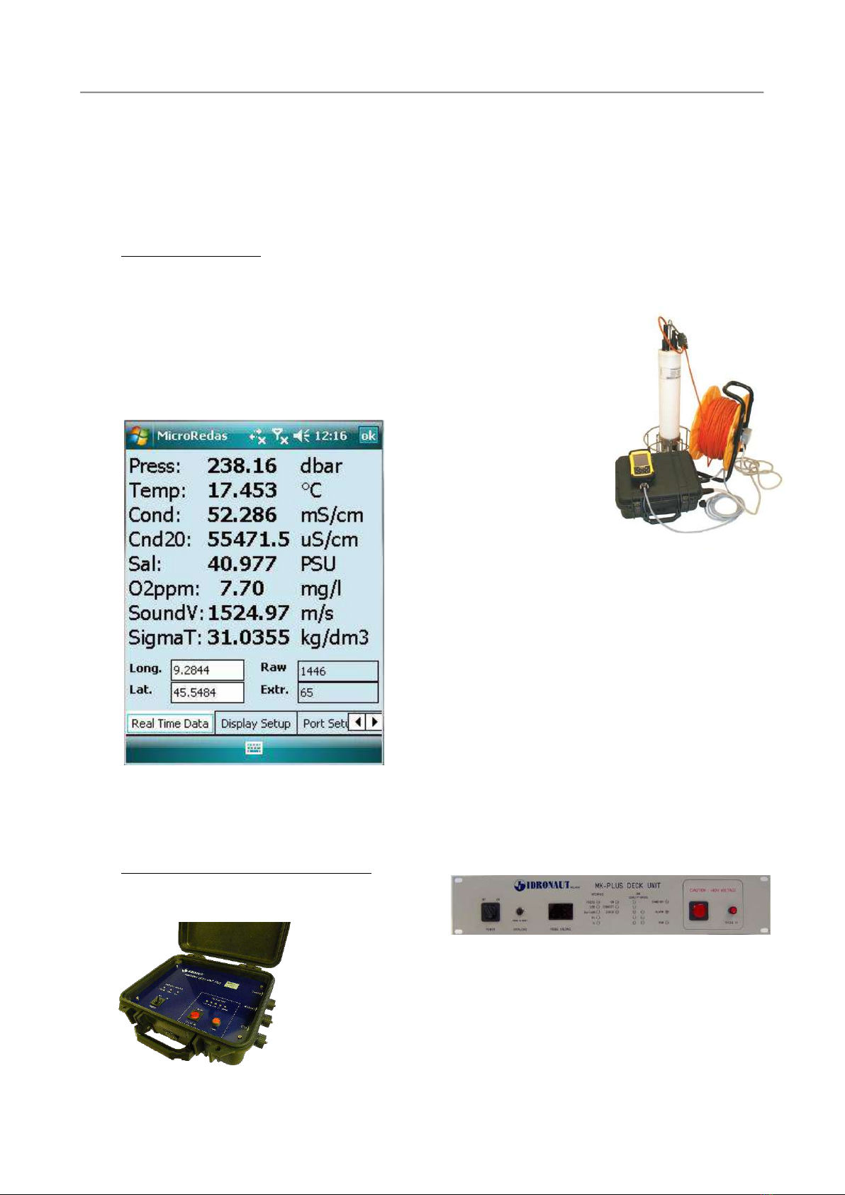
1.5 PORTABLE READER
The OCEAN SEVEN 316Plus probe can be interfaced with a portable lightweight and extremely rugged
reader based on a high-performance Intel® XScale™ processor and on the Windows Mobile™ software
for Pocket PC. Through this device, it is possible to perform the operations
usually carried out by means of a portable personal computer, but
without all limitations that the use of a portable computer in the field and
in hostile environments normally implies, like: battery endurance, display
reading under sunlight, water and dust tightness, weight, etc.
The “Portable Reader” interfaces the OCEAN SEVEN 316Plus probe
through a built-in RS232C interface and dedicated IDRONAUT
programmes, specifically
developed for the Windows
Mobile PC operating system:
ZTERM and µREDAS. These
programmes interface the
OCEAN SEVEN 316Plus
probe and allow the operator
to directly dialogue with the
probes directly, thus
performing: sensor calibration, real-time data acquisition,
probe configuration, etc. All these operations are possible
because of the OCEAN SEVEN 316Plus probe functions
included in the management firmware. Furthermore, the
“Portable Reader” not only shows real-time data sent by
the OCEAN SEVEN 316Plus probe, but also stores it. Data
is stored in binary files using the “Portable Reader” main
or extension “Flash” memory, which can be later
transferred to a desktop personal computer using the
Microsoft ActiveSync programme. Data acquired by
means of the “µREDAS” programme can be imported later
on by the REDAS5 programme. Data storage capability of
the “Portable Reader” is only limited by the size of the installed “Flash” compact memory card. The
“Portable Reader” can operate for up to 15 hours continuously. Autonomy of operation of the interfaced
OCEAN SEVEN 316Plus probe depends on the battery installed inside the probe and on the probe
sensor suite.
1.6 IDRONAUT TELEMETRY DECK UNIT
The IDRONAUT Telemetry Deck Unit powers and
interfaces, by coaxial oceanographic cables, the
OCEAN SEVEN
316Plus probe with a
personal computer RS232C interface. The Deck Unit is provided with a
transceiver (modem) which allows half-duplex communication with the
OCEAN SEVEN 316Plus probe. Two types of Deck Units are available:
Portable and On-Board. The first one is provided with an internal mains
rechargeable lead battery (12VDC, 7 A/h) which permits OCEAN SEVEN
316Plus probe operation even in the absence of the mains supply. The On-
Board MKPlus Deck Unit is housed in a 19” rack-mountable unit and is
designed for on-board operations. The On-Board MKPlus Deck Unit
provides high voltage telemetry power supply: 220 VDC to allow the OCEAN SEVEN 316Plus probe to
interface and power several additional power-hungry instruments like: GENERAL OCEANICS Rosette,
SECTION ONE –SYSTEM DESCRIPTION
IDRONAUT –Brugherio (MB) OCEAN SEVEN 316Plus PROBE 03-2018
4
Altimeter, Fluorometer, Transmissometer, etc.
1.7 INTERNAL BATTERIES
The OCEAN SEVEN 316Plus probe housing has in its upper part enough
space to accommodate an internal battery pack (The battery pack cannot
be installed if the optional data telemetry is installed). This is used
whenever the probe performs unattended acquisition cycles without the
connection in real time with a surface unit (PC). The internal rechargeable
battery pack contains 12 (twelve) batteries: 1.2 V 2.85Ah, NiMH cells. The
battery pack comes complete with an international battery charger.
When the probe is not used for long periods (e.g. 2 weeks or more), we suggest disconnecting the
internal battery pack connector from the probe electronics or removing the internal battery pack from
the probe to prevent the internal batteries from damaging the probe due to battery acid leakage. This is
why the OCEAN SEVEN 316Plus is shipped without batteries installed. Please be aware that it is not
possible to recharge them when they are installed inside the probe
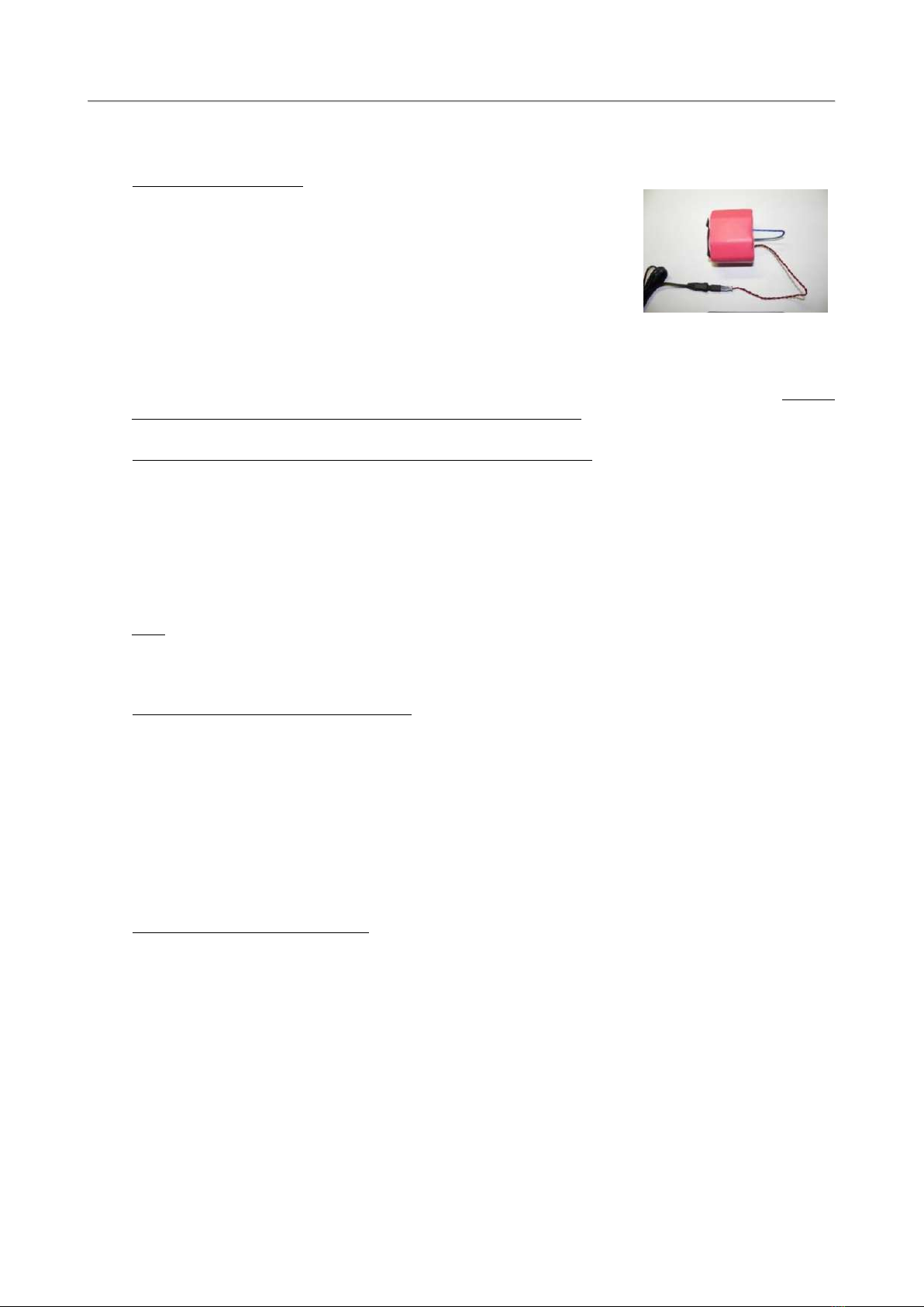
1.8 EXTERNAL SUBMERSIBLE RECHARGEABLE BATTERY PACKS
To overcome the limited autonomy of the internal battery pack, IDRONAUT developed two external
submersible rechargeable battery packs that considerably increase the probe operating autonomy. Both
battery packs accept no. 12 cells - 1.2VDC NiMH type HR-4/3FAU10 for a total of 14.4VDC and 4.5 Ah.
The following battery packs are available:
❖ External submersible rechargeable battery pack (Ø 75 x 315 mm), 1500 m max depth operation.
❖ External submersible rechargeable battery pack (Ø 66 x 315 mm), 7000 m max depth operation.
The external battery pack is held by the probe by means of POM flanges and connected to the RS232C
input/output bulkhead connector by means of a submersible cable.
Note
The presence of the external battery pack does not interfere with the installation of the internal battery pack. The
CTD drains energy from the higher voltage battery pack.
1.9 MAGNETIC POWER ON/OFF SWITCH
The OCEAN SEVEN 316Plus probe is equipped with a magnetic power ON/OFF switch, which allows
the operator to effectively switch ON and OFF the probe. The probe is also able to switch on and off
by itself whenever it performs self-recording acquisition cycles and uses the internal and/or external
battery pack. The magnetic power ON/OFF switch is not used and is bypassed when the probe is used
with data telemetry (please remove the internal batteries, if any, before operating the probe through
the telemetry system). This switch also allows the operator to easily deploy a probe that is pre-
configured to perform unattended data acquisition cycles and which will be switched ON by means of
the power ON/OFF switch. When switching ON/OFF the probe by means of the magnetic switch,
please wait at least 60 seconds between consecutive ON/OFF cycles.
1.10 MANAGEMENT PROGRAMMES
IDRONAUT programmes designed for the Windows 32/64bit operating systems allow the operator to
communicate with the OCEAN SEVEN 316Plus probe to perform attended or unattended data
acquisitions. Programmes include functions to upload data from the 512-MByte internal memory when
the probe acts as a logger. The available programmes are:
ITERM: IDRONAUT terminal emulation and probe management program to easily communicate
with the OCEAN SEVEN 316Plus CTD multiparameter probe. Diagnostic and dedicated
functions are included.
ZTERM: Terminal emulation program for Windows Mobile Operating system. Terminal emulation
program to easily communicate with the OS316Plus CTD multiparameter probe.
uREDAS IDRONAUT real-time data acquisition software for Windows Mobile operating system. It allows

SECTION ONE –SYSTEM DESCRIPTION
IDRONAUT –Brugherio (MB) OCEAN SEVEN 316Plus PROBE 03-2018
5
acquiring and displaying data in real time storing it for later retrieval and processing using
REDAS5 program. While acquiring, up to six different parameters are shown on screen.
REDAS5: Real-time data acquisition, processing and presentation programme, which allows the
numerical display and plotting of the standard sensors and the derived variables such as
salinity, sound speed, density, according to the UNESCO formulas and recommendations.
MULTIPLEX: Multiplex programme, which allows the acquisition from up to 16 OCEAN SEVEN 316Plus
CTDs connected to a single personal computer. Data acquired in real time by means of the
Multiplex programme can be later processed using the REDAS5 programme.
1.11 STANDARD SENSOR SPECIFICATIONS
Parameter Range Accuracy Resolution Time Constant
Pressure 0.. 1000 dbar* 0.05 % F.S. 0.002 % F.S. 50 ms
Temperature -3.. +50 °C 0.003 °C 0.0002 °C 50 ms
Conductivity 0.. 70 mS/cm 0.003 mS/cm 0.0003 mS/cm 50 ms+
Oxygen (polarographic) 0.. 50 ppm 0.1 ppm 0.01 ppm 3 s++
0.. 500 % sat. 1 % sat. 0.1 % sat. 3 s++
Oxygen (optical) 0.. 45 mg/l 0.1 mg/l 0.025 mg/l 2 s++
0.. 250 % sat. ±0.2 % sat. 0.05 % sat. 2 s++
pH 0.. 14 pH 0.01 pH 0.001 pH 3 s
Redox +/-1000 mV 1 mV 0.1 mV 3 s
Auxiliary inputs ** 0..5000 mV 1 mV 0.1 mV 50 ms
* other standard pressure transducers, immediately available, have 10, 40, 100, 200, 500, 2000, 4000, 6000, 10000 dbar ranges.
+ at 1 m/second flow rate ++ from nitrogen to air.
**6 auxiliary analogue inputs.
The fundamental properties of seawater, like:
Salinity, Sound Speed, Water Density, Oxygen ppm are automatically calculated using the algorithms
described in the UNESCO technical papers in marine science no. 44 "Algorithms for computation of
fundamental properties of seawater".
The freshwater properties, like:
TDS (Total Dissolved Solids), Fresh Water Conductivity corrected at 20°C and 25°C are automatically
calculated.
1.12 OPTIONAL SENSOR SPECIFICATIONS
Among others, the OCEAN SEVEN 316Plus CTD can be optionally equipped with the Highly Accurate
Precise (0.01%) Pressure Transducer, the optical IDRONAUT OEM SEAPOINT Turbidity and
Fluorometer sensors, the IDRONAUT OEM CHELSEA Single-Channel and Three-Channel
Fluorimeters.
Parameter Range Accuracy Resolution Time Constant
Pressure (1) 0..10000 dbar 0.01 % F.S. 0.002 % F.S. 50 ms
Turbidity Meter(2) 0.03.. 25 FTU/NTU 0.05 FTU/NTU 0.005 FTU/NTU 0.1 s
0.03.. 125 FTU/NTU 0.25 FTU/NTU 0.025 FTU/NTU 0.1 s
0.03.. 500 FTU/NTU 1 FTU/NTU 0.1 FTU/NTU 0.1 s
0.03.. 750 FTU/NTU** 5 FTU/NTU 0.5 FTU/NTU 0.1 s
0.03..4000 FTU/NTU*** 5 FTU/NTU 0.5 FTU/NTU 0.1 s
** output is non-linear above 750 FTU/NTU

SECTION ONE –SYSTEM DESCRIPTION
IDRONAUT –Brugherio (MB) OCEAN SEVEN 316Plus PROBE 03-2018
6
*** output is non-linear above 1250 FTU/NTU
Please contact Idronaut to get the correct range.
Fluorometer() 0.02..5 µg/l 0.05 µg/l 0.002 µg/l 0.1 s
0.02..15 µg/l 0.1 µg/l 0.006 µg/l 0.1 s
0.02..50 µg/l 0.5 µg/l 0.02 µg/l 0.1 s
0.02..150 µg/l l 1 µg/l 0.06 µg/l 0.1 s
Chlorophyll-a(3)(4)0..100 µg/l < 0.01 µg/l
Fluorescein(3)(4)0..100 µg/l < 0.005 µg/l
Rhodamine WT(3)(4)0..100 µg/l < 0.02 µg/l
Phycoerythrin(3)(4)0..100 µg/l < 0.02 µg/l
Phycocyanin(3)(4)0..100 µg/l < 0.01 µg/l
Nephelometer/Turb. (3)(4)0..100 FTU < 0.02 FTU
Notes
1 - Available ranges are: 100, 1000, 3000, 4000, 7000 and 10000 dbar.
2 - Specifications refer to the IDRONAUT OEM SEAPOINT Turbidity meter and Fluorometer.
3 - Specifications refer to the IDRONAUT OEM Single-channel and Three-channel Chelsea Fluorimeters. The
Three- channel fluorimeter can accommodate the following parameters: Chlorophyll a, Turbidity,
Phycocyanin, Phycoerythrin, in a single sensor.
4 - User configurable up to 500 µg/L or 500 FTU.
1.13 ELECTRONIC SPECIFICATIONS
Sampling rate: user selectable: 12 and 20 Hz raw data CTD using REDAS5 software.
Communication protocol: proprietary binary and plain message protocol.
Operator interface: friendly menu-driven user interface.
Data memory: 2-Gbyte non-volatile memory.
Battery power supply: 9 .. 18 V, 150 mA @ 12 V.
1.14 PHYSICAL CHARACTERISTICS
1500 dbar 1500 dbar 7000 dbar
Dimensions: housing diameter: 100 mm 75 mm 89 mm
total length: 710 mm 685 mm 760 mm
Weight: in air: 4,2 kg 4,0 kg 8,0 kg
in water: 0.2 kg 1,7 kg 4,3 kg
Materials: white POM black POM/ AISI316L TITANIUM GR5
Diameter of protective cage/s: 260 mm, titanium.
1.15 THE STANDARD SENSORS
This section provides a detailed presentation of the OCEAN SEVEN sensors.
1.15.1 The pressure sensor
The pressure sensor is a high quality strain gauge, centrally mounted on the probe base, capable of
generating a linear signal output, thus giving a resolution of 0.03% over the whole measuring range of
0 - 10000 dbar

SECTION ONE –SYSTEM DESCRIPTION
IDRONAUT –Brugherio (MB) OCEAN SEVEN 316Plus PROBE 03-2018
7
Type: strain gauge
Measurement range: 0..10000 dbar
Accuracy: 0.05%FS
Resolution 0.002%FS
Response time: 50 ms @1 m/s
Measurement bridge resistance: @ 25°C Ω 3500 ± 20%
Excitation current: 0.6 mA
Insulation: @ 50 VCC MΩ 100
Operating temperature: °C -30…100
Sensor body: AISI 316L
Compensation: automatic compensation for temperature variations; not
compensated for the barometric pressure variations.
Life: unlimited.
Calibration frequency: monthly.
Maintenance: offset calibration in air.
1.15.2 The temperature sensor
The temperature sensor consists of a platinum resistance thermometer (type Pt 100 ohms at 0°C), fitted
on a thin stainless steel housing, able to withstand up to 700 bar. The sensor has a very low response
time (50 ms) and a high stability of reading with ageing. The drift of
reading (sensor plus associated electronics) is less than 0.0003 °C per
year.
Type: Pt100@0°C
Measurement range: -3..+50 °C
Accuracy: 0.003 °C
Resolution: 0.0002 °C
Response time: 50 ms @1 m/s
Maximum pressure: 700 bar
Sensor body: AISI 316L
Life: unlimited
Calibration frequency: yearly
Compensation: none.
Maintenance: none.
1.15.3 The conductivity sensor equipped with the "IDRONAUT seven-ring cell"
The conductivity sensor is a unique flow-through self-flushed cell with seven platinum ring electrodes.
The central ring is excited with alternate current flowing to both the outermost rings. The two adjacent
pairs of rings sense the relative drop in voltage due to the electrical conductivity of the measured water.
The outermost pair of rings is grounded to shield the measuring cell from any outside electrical
interference. The cell is mounted in a special cylindrical plastic body, which guarantees thermic
insulation and is filled with silicone oil and provided with a rubber bellow to achieve pressure
compensation.
The IDRONAUT conductivity sensor and its associated electronics are designed to work both with plain
and black platinised platinum electrodes These electrodes have the advantage that, they can be used in
both clean and dirty water without the fear of contamination. Should electrode contamination occur,
they can be easily cleaned (even with up to 30% hydrochloric acid) without affecting the CTD
performance or requiring re-calibration. Because of its big internal diameter and short length, the cell
does not need a pump, as it is easily flushed during profiles.
The other conductivity flow cell sensors available on the market do not have the technology of the
“IDRONAUT seven-ring cell”.
The small, closely spaced temperature and conductivity free-flow sensors eliminate the need for adding
pumping. Time constant of the conductivity sensor is 50 ms, at 1 meter per second water flow.

SECTION ONE –SYSTEM DESCRIPTION
IDRONAUT –Brugherio (MB) OCEAN SEVEN 316Plus PROBE 03-2018
8
Measurement cell: 7 platinum rings deposited inside
a quartz tube. Internal diameter
8mm, length 45mm.
Measurement range: 0..70 mS/cm
Accuracy: 0.003 mS/cm
Resolution: 0.0003 mS/cm
Response time: 50 ms @1 m/s
Max pressure: 700 bar
Sensor body: black plastic and titanium
Compensation: automatic compensation of the
pressure and thermal effect on the
cell geometry are performed by
the acquisition software.
Life: unlimited.
Calibration frequency: yearly.
Maintenance: cleaning using the IDRONAUT
“Conductivity sensor cleaning
solution”.
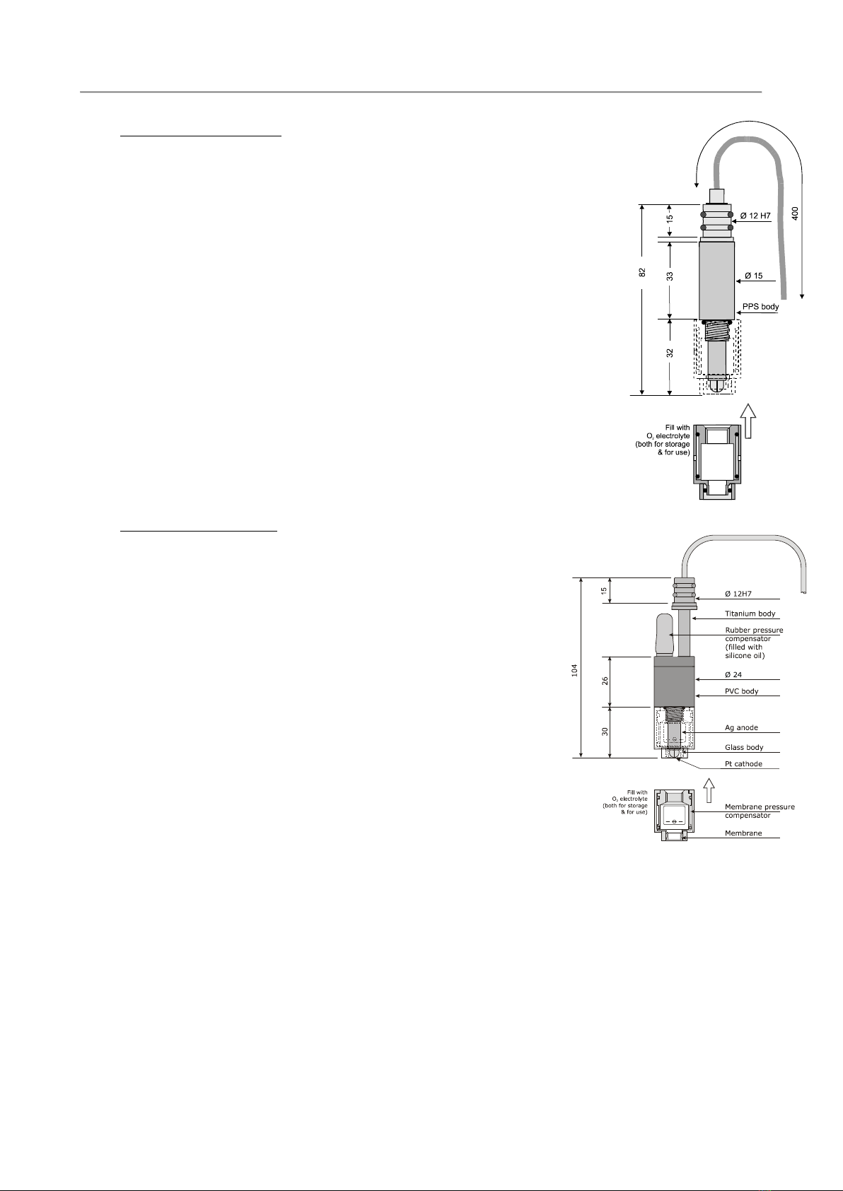
1.15.4 The oxygen sensor (standard 150bar and 700 bar versions)
The oxygen sensor is of the polarographic type and consists of two half-cells, the anode and the cathode.
The anode is a silver tube inside the sensor, which encircles a glass body where a platinum wire, forming
the cathode, is sealed. The platinum wire (cathode) ends at the tip of the sensor where the glass body is
rounded. A special membrane cap with a gas-permeable replaceable membrane screws onto the sensor.
The inside of the cap is filled with a special electrolyte which allows the current (measuring) to flow
between the anode and the cathode. The membrane is shielded from accidental bumps by a protective
ring. The anode acts as a reference cell, providing a constant potential with respect to the cathode. The
cathode, where oxygen is consumed or reduced, is separated from the sample to be analyzed by a thin
layer of electrolyte and a special composite membrane. The electrolyte permits the chemical reaction to
occur whereas the membrane constitutes a barrier against ions and other substances. By applying a
polarizing voltage to the half-cells, the sensor develops a current proportional to the concentration of
oxygen in the sample in front of the cathode. Oxygen from the sample is drawn across the membrane,
at the sensor tip, in the area of the cathode. The applied polarization voltage is such that the sensor only
responds to oxygen. The sensor is insensitive to nitrogen, nitrous oxide, carbon dioxide and other gases.
In order to avoid stray ground current leaks, in case of membrane leaks, the anode is kept at ground
potential while the cathode is polarized at a fixed negative voltage. The oxygen sensor limits stirring
effects on the measurement and reads at least 97% of the true value, even with a stagnant aqueous
sample. This is because the very small cathode area and special cathode geometry, associated with a
unique composite membrane, minimize the consumption of the oxygen contained in the sample in
contact with the membrane. The function of this sensor depends on the reduction of oxygen at the
cathode, as expressed by the formula:
O2+ 2 H2O + 4e->>> 4 OH-
The developed electrons represent the measuring current and are supplied by the silver/silver chloride anode.
SECTION ONE –SYSTEM DESCRIPTION
IDRONAUT –Brugherio (MB) OCEAN SEVEN 316Plus PROBE 03-2018
9
Standard version, 150 bar
Type: polarographic with Pt/Ir cathode and
Ag(99.99%) anode.
Measurement range: 0... 50 ppm 0… 500% sat.
Accuracy: 0.1 ppm 1 % sat.
Resolution: 0.01 ppm 0.1% sat.
Polarization voltage: 650 mV DC.
Response time: 3s (green membrane @20°C)
0.9 s (blue membrane @20°C)
Max Pressure: 150 bar.
Sensor body: plastic and titanium.
Compensation: automatic compensation of pressure and
thermal variations.
Life: 2 years if intensively used to perform
continuous monitoring, up to 4 years if
used weekly to perform daily profiling or
monitoring.
Calibration frequency: weekly.
Maintenance: measuring membrane replacement,
electrolyte replacement
Standard version 700 bar
Type: polarographic with Pt/Ir
cathode and Ag(99.99%) anode
Measurement range: 0... 50 ppm 0… 500% sat.
Accuracy: 0.1 ppm 1 % sat.
Resolution: 0.01 ppm 0.1% sat.
Polarization voltage: 650 mV DC
Response time: 3s @20°C
Max Pressure: 700 bar
Sensor body: titanium.
Compensation: automatic compensation of
pressure and thermal
variations.
Life: 2 years if intensively used to
perform continuous monitoring,
up to 4 years if used weekly to
perform daily profiling or
monitoring.
Calibration frequency: weekly.
Maintenance: measuring membrane replacement,
electrolyte replacement.
Table of contents
Other idronaut Measuring Instrument manuals


