PKP DP05 User manual

Instruction Manual
DP05 / DP06
Paddle bellows flow switch / meter
PKP Prozessmesstechnik GmbH
Borsigstraße 24
D-65205 Wiesbaden- ordenstadt
Tel.: ++49-(0)6122-7055-0
Fax: ++49-(0)6122-7055-50
Email: info@pkp.de

Table of Contents
Safety Information..................................................................................................................2
Measuring Principal / Function..............................................................................................3
Mounting.................................................................................................................................3
Process connection................................................................................................................4
Electrical Connection.............................................................................................................6
Calibration dates....................................................................................................................6
Switch-point............................................................................................................................6
Maintenance...........................................................................................................................7
Safety Information
General Instructions
To ensure safe operation, the device should only be operated according to the
specifications in the instruction manual. The requisite Health & Safety regulations for a
given application must also be observed. This statement also applies to the use of
accessories.
Every person who is commissioned with the initiation or operation of this device must have
read and understood the operating instructions and in particular the safety instructions!
The work safety instructions in this manual as well as the safety, accident prevention and
environmental protection regulations generally valid for the work area must be observed.
The liability of the manufacturer expires in the event of damage due to improper use, non-
observance of this operating manual, use of insufficiently qualified personnel and
unauthorized modification of the device.
Pro er Usage
The flow switches / meters DP05 and DP06 are designed to monitor continuous flow rates
of liquids which do not attack the device materials. All other usage is regarded as being
improper and outside the scope of the device.
In particular, applications in which shock loads occur (for example, pulsed operation)
should be discussed and checked in advance with our technical staff.
The series DP05 and DP06 flow meter devices should not be deployed as the sole agents
to prevent dangerous conditions occurring in plant or machinery. Machinery and plant
need to be designed in such a manner that faulty conditions and malfunctions do not arise
that could pose a safety risk for operators.
Dangerous substances
For dangerous media such as e.g. Oxygen, Acetylene, flammable or toxic substances as
well as refrigeration systems, compressors, etc. must comply with the relevant regulations
beyond the general rules.
DP05 / DP06 Instruction manual 07/2020 page 2

Qualified Personnel
The DP05 and DP06 devices may only be installed by trained, qualified personnel who are
able to mount the devices correctly. Qualified personnel are persons, who are familiar with
assembling, installation, placing in service and operating these devices and who are
suitably trained and qualified.
Inward Monitoring
Please check directly after delivery the device for any transport damages and deficiencies.
Additional with reference to the accompanying delivery note the number of parts must be
checked.
Claims for replacement or goods which relate to transport damage can only be considered
valid if the delivery company is notified without delay.
Measuring Princi al / Function
The Flow-Switches and Flow-Meters of types DP05
and DP06 work on the principle of dynamic
pressure.
The flow medium works against a target plate (4),
which causes the system to swing against a tension
spring (1).
A bellows system made from stainless steel (3)
seals the indicator and switch equipment against the
flowing liquid. Connection between the target plate
and the evaluating system is made by a lever arm.
A microswitch (2) is actuated whenever the
preselected low or high flow switch-points are
passed.
Depending from type additionally a control-lamp and
a indication system for the actual flow will be
actuated.
DP05 / DP06 Instruction manual 07/2020 page 3

Mounting
Mounting orientation
The Flow-Switches and Flow-Meters DP05 and DP06 are designed to be installed directly
in a pipe system. Make sure that the instruments are installed according the information
on the type plate. The flow-direction correlates to the direction of the pipe. Inaccuracy of
the instrument will result from incorrect mounting.
Flow direction
It is essential that the unit is mounted so that flow is as indicated by the arrow on the body.
The unit will not
operate unless installed correctly in this way.
Position of mounting
The following points must be observed:
•To avoid damages at the measuring system it is especially important to have the
biggest possible distance from magnet valves and ball valves. If it is not possible to
have a big distance, the valves have to be installed after the instruments. To avoid
pressure shocks it is very important to open the valves slowly.
•It is advantageous to install the unit in a straight piece of pipe and to choose a
place of mounting which has the biggest possible distance from elbows, valves etc.
•In order to have an accurate function of the device we recommend a straight length
of 10 x d at input side and 5 x d at the output side (d= internal diameter of pipe)
DP05 / DP06 Instruction manual 07/2020 page 4

Process connection
Thread connection
We recommend sealing all threads with PTFE sealing tape. Ensure no excess of tape is
left protruding into the pipe.
Flange connection
A approved flange seal or gasket must be used. either this nor the required fixing bolts
are included in the delivery.
Welded socket
The complete flange with screws
and sealing is delivered with the
instrument.
The distance 60 mm has to be
kept exactly, because this directly
affects the calibration of the
instrument.
Drill a ridge less hole in the pipe
and weld on the socket.
Use the enclosed sealing.
Please keep the flow direction in
consideration during mounting
procedure (arrow).
The pipe must be free from
pollution.
DP05 / DP06 Instruction manual 07/2020 page 5

Electrical connection
•Removing the enclosure to gain access to the four polar connector block.
•Additionally to the micro-switch a control lamp is installed. This lamp is for optical
control of switch status of the micro-switch.
•The current which is necessary for the lamp is indicated at the label.
•The max. switching performance is up to 230 V / 10 A AC.
•Please connect the device to ground with help of the screw near cable entry .
Cable ty e to be used
The connection cable to be used must correspond to the required electrical connection
power (max 230 V, 10 A AC). In addition, the prevailing stresses (temperature, mechanical
stress, chemical influences) must be taken into consideration when selecting the cable.
Circuit diagram
Calibration dates
Calibration dates, type of device and serial number are indicated at the label. Changes of
medium, pressure and position of mounting will influence accuracy.
DP05 / DP06 Instruction manual 07/2020 page 6

Switch- oint
DP05, DP06:
Alternations of the switchpoint can be made by the customer within the limits indicated on
the scale.
DP06:
The actual flow is indicated at front side of the unit.
Maintenance
The flow switches and meters DP05 and DP06 are almost maintenance-free. In case of
mal-function first of all check the pipe system for calcification or other obstruction.
For cleaning do not use sharp-edged tools. Damaged instruments can only be repaired in
our factory, because they have to be re-calibrated.
Damaged items should send back to the manufacturer because it is only there possible to
do the recalibration which is necessary.
Unscrewing screws, changing tension spring or bellow system changes calibration and will
invalidate the guarantee.
DP05 / DP06 Instruction manual 07/2020 page 7

Flow Measurement and Monitoring
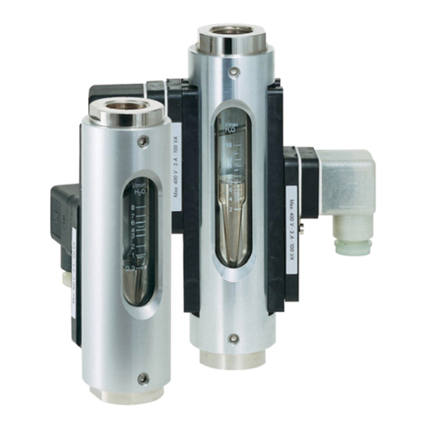
DP05
Paddle-Bellows Flow Switch
with Variable Switching Point
•for liquids
•easy switching- oint adjustment with
small scale
•bellows kee liquid
hermetically se arated from
the switching element
•insensitive to
dirty / contaminated fluids
•high electrical loading ca acity
through use of 1 or 2 inde endently
adjustable microswitches
•insensitive to
electromagnetic fields
•easy installation, for
i ing u to DN 600
•o tical switching dis lay
by signal lam
Description:
The flow switches model DP05 operates according to the
paddle-bellows principle. The flowing liquid pushes against
the surface area of a paddle mounted at the end of a pivoting
arm. The arm is deflected against the force of a spring. This
deflection is mechanically transmitted to an adjustable contact
unit. bellow systems seals the mechanism hermetically from
the liquid.
In case of malfunction, the spring returns the paddle plate to
the zero position (no flow), which causes the system to signal
a fault automatically.
Typical applications:
The DP05 paddle-bellows flow switch is suitable for
monitoring thin and low-viscosity liquids in average to large
flow volumes, eg. for industrial water circuits because they are
relatively insensitive to dirty/contaminated fluids. For nominal
pipe sizes over DN 50, installation with a special intermediate
mounting flange yields a price/performance ratio of
exceptional economy.
PKP Prozessmesstechnik GmbH
Borsigstr. 24 • D-65205 Wiesbaden
S +49 (0) 6122-7055-0 • T +49 (0) 6122 7055-50
[email protected] • www.pkp.de
20181114

Models:
Each of the 3 types of DP05 flow switches are available
in 3 material combinations:
DP05.R… with T-fitting and pipe-thread connection
from R 3/8 to R 2 male thread
DP05.F: with T-fitting and DIN flange
from DN 10 to DN 50
aterial- T-fitting made of brass
combination A pivoting system made of brass
bellows made of st. steel 1.4571
flanges made of galvanized steel
aterial- T-fitting made of st. steel 1.4571
combination B pivoting system made of st. steel 1.4571
bellows made of st. steel 1.4571
flanges made of st. steel 1.4571
aterial- T-fitting made of PVC
combination C pivoting system made of st. steel 1.4571
bellows made of st. steel 1.4571
flanges made of PVC
DP05.A: with weld on flange
for nominal pipe size DN 65 to DN 600
aterial- housing made of brass
combination A pivoting system made of brass
bellows made of st. steel 1.4571
weld-on flange made of steel,
coated, DN 25
aterial- housing made of st. steel 1.4571
combination B pivoting system made of st. steel 1.4571
bellows made of st. steel 1.4571
weld-on flange made of st. steel 1.4571,
DN 25
Dimensions:
Order Code:
Order number: DP05.
Paddle-bellows flow switch
R025. B
.
1. 20-100
Process connection
(xx= nominal pipe size):
R0xx = with male thread (only R 3/8 to R 2)
F0xx = with flange (only DN 10 to DN 50)
xxx = with weld-on-flange (from DN 40 to DN 600)
aterial combination:
= brass / stainless steel / steel zinc plated
B = completely made of stainless steel
C = PVC / stainless steel (not for DP05. ..)
Switching output:
1 = 1 microswitch (250 V / 10 )
2 = 2 microswitches (250 V / 5 )
Switching range:
xxxx-xxxx = min. - max. switch point (see table „Measuring ranges“)
Additional s ecifications:
• medium density and viscosity (if different from water)
• rocess ressure and tem erature
• mounting osition and direction of flow
• ratings of electrical connections
Measuring ranges:
Process-
connection
DP05.R...
DP05.F...
Flow rate
[l/min]
Flow-
ratio
Process-
connection
DP05.A…
Flow rate
[m³/h]
Flow-
ratio
min. max. min. max.
3/8"/DN 10 1 25 1:5 DN 40 1,2 24 1:4
1/2"/DN 15 1 55 1:5 DN 50 3 36 1:4
3/4"/DN 20 5 100 1:5 DN 65 4,8 60 1:4
1"/DN 25 6 150 1:5 DN 80 7,2 90 1:4
1 1/4"/DN 32 10 250 1:5 DN 100 12 144 1:4
1 1/2"/DN 40 20 400 1:5 DN 125 18 255 1:4
2"/DN 50 50 600 1:5 DN 150 24 330 1:4
Switching ranges apply to water at
20°C. Within the specified limits, all
switching ranges can be achieved,
provided that the max./min. ratio for
the switching point is not exceeded.
e.g. in the event of 1/2“: 1-5, 2-10 or
11-55 possible.
DN 200 42 600 1:4
DN 250 72 900 1:4
DN 300 102 1.200 1:4
DN 350 150 1.800 1:4
DN 400 180 2.400 1:4
DN 500 300 3.600 1:4
DN 600 420 4.500 1:4
Nominal size Installation length Z [mm] Installation height
H
[mm]
DP05.R… DP05.F…
3/8"/DN 10 135 155 145
1/2"/DN 15 135 155 145
3/4"/DN 20 135 160 145
1"/DN 25 135 160 145
1 1/4"/DN 32 170 190 150
1 1/2"/DN 40 170 190 155
2"/DN 50 170 190 160
Technical Data:
ax. pressure: 16 bar
max. med.-temperature: 100 °C (higher on request)
Accuracy: ± 5 % up to 20 l/min
± 4 % from 21…200 l/min
± 3 % > 200 l/min
Switching hysteresis: 10 % (up to 2 bar)
Contacts: microswitch, 250 V, 10
Status display:
Protection class:
glow lamp or LED
(depending on the con. voltage)
IP55 (IP65 on request)
Please specify the connection voltage 24 V or 230 V.
PKP Prozessmesstechnik GmbH
Borsigstr. 24 • D-65205 Wiesbaden
S +49 (0) 6122-7055-0 • T +49 (0) 6122 7055-50
[email protected] • www.pkp.de
Flow

Flow Measurement and Monitoring
DP06
Paddle-Bellows Flow Meter
and Switch
•for liquids
•large 270°-dial gauge dis lay
for flow rate
•sim le switch- oint adjustment
over the entire switching range
on a se arate small scale
•bellows kee liquid hermetically
se arated from the switching element
•insensitive to dirty / contaminated
fluids
•high electrical loading ca acity
through use of 1 or 2 inde endently
adjustable microswitches
•insensitive to electromagnetic fields
•easy installation, for i es u to DN 600
Description:
The flow meters and switches model DP06 operate according
to the paddle-bellows principle. The flowing liquid pushes
against the surface area of a paddle mounted at the end of a
pivoting arm.
The arm is deflected against the force of a spring. This
deflection is mechanically transmitted to a 2 0° dial-gauge
display and a separately adjustable contact unit. A bellow
system seals the liquid off from the mechanism. In case of
malfunction, the spring returns the paddle plate to the zero
position (no flow), which causes the system to automatically
signal a fault.
Typical Applications:
The DP06 paddle-bellows flow meter and switch is suitable for
monitoring thin and low-viscosity liquids in average to large
flow volumes, e.g. for industrial water circuits because they are
relatively insensitive to dirty / contaminated fluids.
For nominal pipe sizes over DN 50, installation with an
intermediate mounting flange yields a price/ performance ratio
of exceptional economy.
PKP Prozessmesstechnik GmbH
Borsigstr. 24 • D-65205 Wiesbaden
S +49 (0) 6122- 055-0 • T +49 (0) 6122 055-50
[email protected] • www.pkp.de
20181114

Models:
Each of the 3 types of DP06 flow meters and switches are
available in 3 material combinations:
DP06.R… with T-fitting and pipe size connection
from R 3/8 to R 2 male thread
DP06. … with T-fitting and DIN-flange
from DN 10 to DN 50
Material- T-fitting made of brass
combination A pivoting system made of brass
bellows made of st. steel 1.45 1
flange made of galvanized carbon steel
Material- T-fitting made of st. steel 1.45 1
combination B pivoting system made of st. steel 1.45 1
bellows made of st. steel 1.45 1
flange made of st. steel 1.45 1
Material- T-fitting made of PVC
combination C pivoting system made of st. steel 1.45 1
bellows made of st. steel 1.45 1
flange made of PVC
DP06.A… with weld on flange for
nominal pipe size DN 65 to DN 600
Material- housing made of brass
combination A pivoting system made of brass
bellows made of st. steel 1.45 1
weld on flange made of carbon steel,
painted
Material- housing made of st. steel 1.45 1
combination B pivoting system made of st. steel 1.45 1
bellows made of st. steel 1.45 1
weld-on flange made of st. steel 1.45 1
Dimensions:
Order Code:
Order number: DP06.
Paddle bellows flow meter and switch
R025. B. 1. 20-100
Process connection
(xx=nominal pipe size):
R0xx = with male thread (R 3/8 to R 2 only)
F0xx = with flange (DN 10 to DN 50 only)
Axxx = with weld on flange (from DN 40 to DN 600)
Material combination:
A = brass / st. steel / steel zinc plated
B = completely of st. steel
C = PVC / st. steel (not for DP06.A..)
Contact:
1 = 1 microswitch (250 V / 10 A)
2 = 2 microswitches (250 V / 5 A)
Switching range:
xxxx-xxxx = min. - max. flow rate (see table „Measuring ranges“)
Additional s ecifications:
• medium density and viscosity (if different from water)
• rocess ressure and tem eratures
• mounting osition and direction of flow
• ratings of electrical connections
Measuring ranges:
Process-
connection
DP06.R...
DP06. ...
low rate
[l/min]
low-
ratio
Process-
connection
DP06.A…
low rate
[m³/h]
low-
ratio
min. max. min. max.
3/8"/DN 10 1 25 1:5 DN 40 1,2 24 1:4
1/2"/DN 15 1 55 1:5 DN 50 3 36 1:4
3/4"/DN 20 5 100 1:5 DN 65 4,8 60 1:4
1"/DN 25 6 150 1:5 DN 80 ,2 90 1:4
1 1/4"/DN 32 10 250 1:5 DN 100 12 144 1:4
1 1/2"/DN 40 20 400 1:5 DN 125 18 255 1:4
2"/DN 50 50 600 1:5 DN 150 24 330 1:4
Switching ranges apply to water at,
20 °C. Within the specified limits, all
switching ranges can be achieved, on
condition that the max./min. ratio
for the switching point is not
exceeded.
e.g. in the case of 1/2”: 1-5, 2-10 or
11-55 is possible.
DN 200 42 600 1:4
DN 250 2 900 1:4
DN 300 102 1.200 1:4
DN 350 150 1.800 1:4
DN 400 180 2.400 1:4
DN 500 300 3.600 1:4
DN 600 420 4.500 1:4
Nominal size Installation length Z [mm] Installation
height H
[mm]
DP06.R… DP06. …
3/8"/DN 10 135 155 145
1/2"/DN 15 135 155 145
3/4"/DN 20 135 160 145
1"/DN 25 135 160 145
1 1/4"/DN 32 1 0 190 150
1 1/2"/DN 40 1 0 190 155
2"/DN 50 1 0 190 160
Technical Data:
Max. pressure: 16 bar
Max. med.-temperature: 100 °C (higher on request)
Accuracy: ± 5 % up to 20 l/min
± 4 % from 21…200 l/min
± 3 % > 200 l/min
Switching hysteresis: 10 % (bis 2 bar)
Contacts: microswitch, 250 V, 10 A
Status display: glow lamp or LED
(depending on the con. voltage)
Protection Class: IP55 (IP65 on request)
Please specify the connection voltage 24 V or 230 V.
PKP Prozessmesstechnik GmbH
Borsigstr. 24 • D-65205 Wiesbaden
S +49 (0) 6122- 055-0 • T +49 (0) 6122 055-50
[email protected] • www.pkp.de
Flow
This manual suits for next models
1
Table of contents
Other PKP Measuring Instrument manuals