idronaut OCEAN SEVEN 306 User manual

OCEAN SEVEN 306
pH and redox probe
OPERATOR'S MANUAL
Copyright @ 1982 –2015 Idronaut S.r.l. All rights reserved.
OCEAN SEVEN and Idronaut are registered trademarks of Idronaut S.r.l.
Other products and services mentioned in this document are identified by the trademarks or service marks of their respective
companies or organisations. No part of this publication, or any software included with it, may be reproduced, stored in a retrieval
system, or transmitted in any form or by any means, including photocopying, electronic, mechanical, recording or otherwise, without
the prior written permission of the copyright holder. Idronaut S.r.l. provides this document as is without warranty of any kind either
expressed or implied including, but not limited to, the implied warranties of merchantability and fitness for a particular purpose.
Idronaut S.r.l. may make changes of improvements in the equipment, software, firmware, or specifications described in this document
at any time and without notice. These changes may be incorporated in new releases of this document. This document may contain
technical inaccuracies or typographical errors. Idronaut S.r.l. waives responsibility of any labour, materials, or costs incurred by any
person or party as a result of using this document. Idronaut S.r.l. shall not be liable for any damages (including, but not limited to,
consequential, indirect or incidental, special damages, or loss of profits or data) even if they were foreseeable and Idronaut S.r.l. has
been informed of their potential occurrence arising out of or in connection with this document or its use.

IDRONAUT –Brugherio (MI) OCEAN SEVEN 306 12-2015
Copyright statement
Copyright IDRONAUT S.r.l.
OCEAN SEVEN and IDRONAUT are registered trademarks of IDRONAUT S.r.l. All rights reserved.
This document may not, in whole or in part, be copied, photocopied, reproduced, translated, or reduced to
any electronic medium or machine-readable form without prior consent in writing from IDRONAUT S.r.l.
About this manual
This manual will serve as a guide to you when you use the OCEAN SEVEN 306 probe.
Use it to understand the purpose of each of the OCEAN SEVEN 306 probe components and
functions.
It will help you to understand the OCEAN SEVEN 306 probe behaviour.
It will serve you as a reference when some problems arise when using the OCEAN SEVEN 306
probe.
Software updates and technical support
Please visit our website download area for software updates and technical support: http://www.idronaut.it
Warranty
The OCEAN SEVEN 306 probe is covered under a one-year limited warranty that extends to all parts and
labours and covers any malfunction that is due to poor workmanship or due to errors in the manufacturing
process. The warranty does not cover shortcomings that are due to the design, nor does it cover any form of
consequential damage as a result of errors in the measurements. If there is a problem with your IDRONAUT
OCEAN SEVEN 306 probe, first try to identify the problem by following the procedure outlined in the
troubleshooting section of this manual, if any. Please contact your representative or IDRONAUT S.r.l.. if the
problem is identified as a hardware problem or if you need additional help in identifying the problem.
Please make sure to contact IDRONAUT S.r.l. to obtain the relevant instructions before the OCEAN
SEVEN 306 probe is returned to IDRONAUT (see cleaning instructions).
For systems under warranty, IDRONAUT S.r.l. will attempt to ship replacement parts before the
malfunctioning part is returned. We encourage you to contact us immediately if a problem is detected and
we will do our best to minimize the downtime. Every effort has been made to ensure the accuracy of this
manual. However, IDRONAUT S.r.l. makes no warranties with respect to this documentation and disclaims
any implied warranties of merchantability and fitness for a particular purpose. IDRONAUT S.r.l. shall not be
liable for any errors or for incidental or consequential damages in connection with the supply, performance
or use of this manual or the examples herein. The information in this document is subject to change without
notice.
Disposal of Waste Equipment by Users in the European Union
The recycling bin symbol on the product or on its packaging indicates that this product must not be disposed
of with your other waste. It is your responsibility to dispose of your waste equipment by handling it over to
a designated collection point for the recycling of waste electrical and electronic equipment. The separate
collection and recycling of your waste equipment at the time of disposal will help to conserve natural
resources and ensure that it is recycled in a manner that protects human health and the environment. For
more information about where you can drop off your waste equipment for recycling, please contact your
local city office, your waste disposal service.

IDRONAUT –Brugherio (MI) OCEAN SEVEN 306 12-2015
TABLE OF CONTENTS
1. INTRODUCTION 1
1.1. pH AND REFERENCE SENSORS 1
1.1.1. pH sensor 1
1.1.2. Reference sensor 2
1.2. THE REDOX SENSOR 2
1.3. TECHNICAL SPECIFICATIONS 3
1.3.1. AISI 316L housing - 600 bar 3
1.3.2. White POM housing - 150 bar 4
1.4. SENSOR WIRING 7
1.5. SHIPPING LIST 8
2. DAILY OPERATIONS 8
3. CALIBRATION 8
3.1. REFERENCE SENSOR QUALITY 8
3.2. pH BUFFER TRUE VALUE 9
4. pH CALCULATION AND CORRECTION 9
5. REDOX CALCULATION 10
6. MAINTENANCE 11
6.1. REFERENCE SENSOR 11
6.2. pH SENSOR 11
6.2.1. To etch the sensor, perform the following: 11
6.2.2. Important remark on the pH measurement 12
6.3. REDOX SENSOR 12
7. OCEAN SEVEN 306 –ELECTRONIC SCHEMATICS 13
7.1. CUSTOMIZATION of the pH SENSOR MEASURING RANGE 15
7.2. DETERMINATION OF THE pH SLOPE FACTOR 15

OCEAN SEVEN 306 - pH and redox probe 1
IDRONAUT –Brugherio (MI) OCEAN SEVEN 306 12-2015
1. INTRODUCTION
The OCEAN SEVEN 306 pH and redox combined sensor probe is provided with an analogue output
0..5V and allows the in situ determination of pH and redox (oxidation reduction potential) in natural
waters as oceans, lakes, rivers and estuaries, at depths down to 600 bar. The OCEAN SEVEN 306 pH
and redox combined sensor, is specifically designed to simplify the integration in CTD probes.
1.1. pH AND REFERENCE SENSORS
The measurement of pH in seawater demands high accuracy since seawater has a high ionic strength
and is weakly buffered. The pH range in the oceans is particularly restricted and, only in very special
cases, the observed values are outside the range of 7.8 and 8.4 pH and, in some seas, the range extends
from 6.5 to 9.0 pH. Some problems have always arisen from the use of traditional reference sensors
with porous diaphragms, when measuring the pH in seawater, in particular at pressures in excess of a
few bars, due to the high and variable junction potentials that are generated. The IDRONAUT
reference sensor is in contact with the unknown solution by means of a small hole in the glass tip. This
minimizes and stabilizes the junction potential between the inner gel electrolyte and the liquid to be
measured. The reference sensor is a Silver/Silver Chloride cell in a saturated potassium chloride solid
gel and the sensor head is made of titanium.
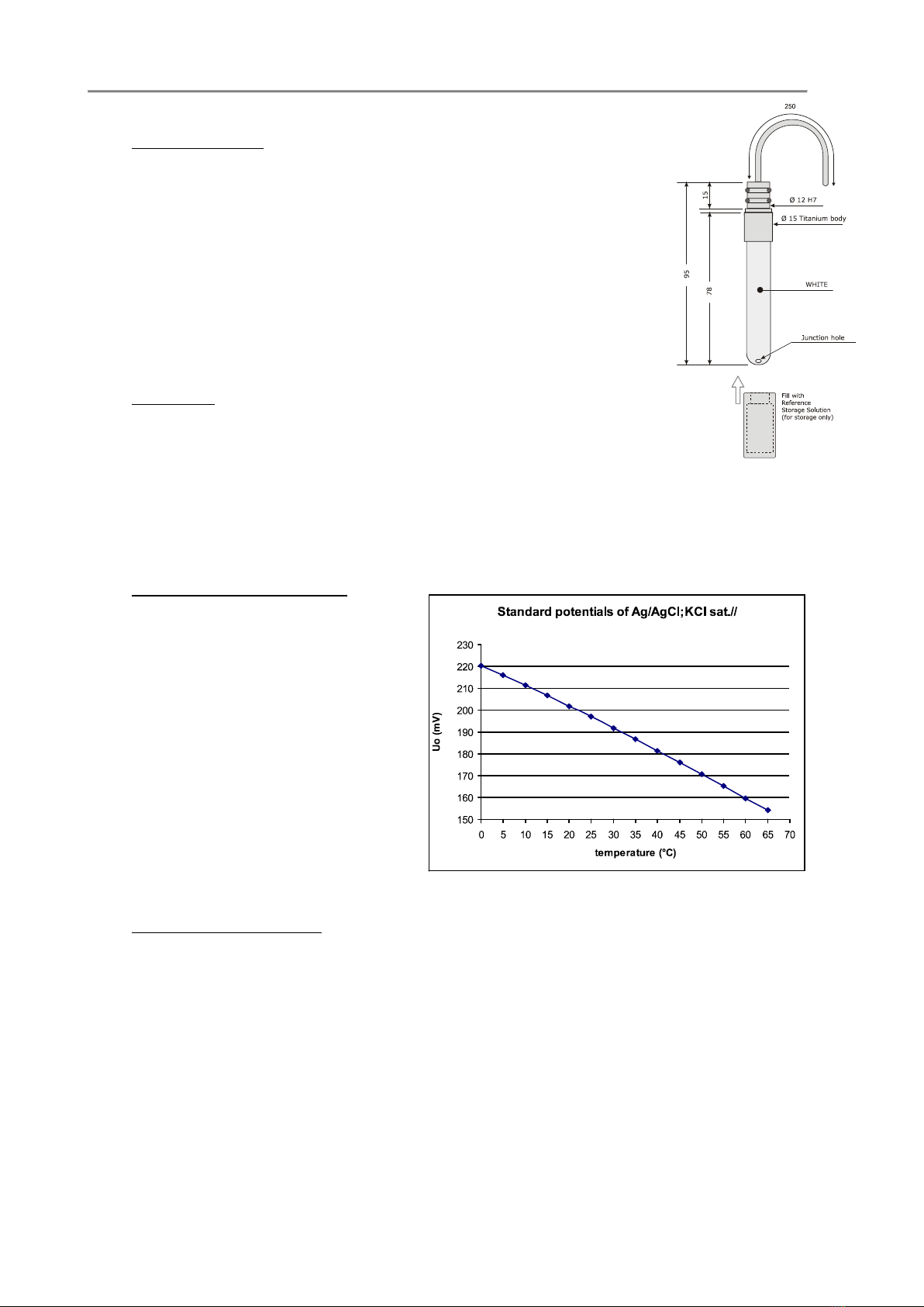
It is also available a reference sensor specifically developed for long-term monitoring of seawater
where the internal cell is 0.7 mol NaCl. The glass body of the sensor is fitted with a plastic hydrating
cap filled with the IDRONAUT REFERENCE SENSOR STORAGE SOLUTION based on 3-mol KCl (or
NaCl) or, if not available, even with KCl saturated solution to avoid drying of the gel when not in use.
This cap must be removed before measurements. The pH sensor has a titanium head, a glass body
and a pH sensitive glass tip, which can withstand pressures up to 150 bar or even 700 bar (special
version). During all periods of inactivity, the glass tip must be fitted with a white plastic hydrating cap
filled with the pH 7 Buffer Solution, or simply with clean water. This is to prevent the pH-sensitive
glass from dehydration, which slows down the sensor response. This cap must be removed before
measurements.
1.1.1. pH sensor
Type: blue glass membrane (100 MOhm @ 20°C).
Measurement range: 0..+14 pH.
Accuracy: 0.01 pH.
Resolution: 0.001 pH.
Drift: 0.05 pH/month.
Response time: 3 s.
Max pressure: 700 bar.
Sensor body: titanium.
Compensation: automatic thermal compensation.
Life: 2 years if intensively used to for
monitoring, up to 4 years if used weekly for
daily profiling or monitoring.
Calibration frequency: monthly.
Maintenance: glass membrane renewing using the pH Sensor
Etching Solution.
OCEAN SEVEN 306 - pH and redox probe 2
IDRONAUT –Brugherio (MI) OCEAN SEVEN 306 12-2015
1.1.2. Reference sensor
Internal cell: Ag/AgCl filled with solid gel.
Max pressure: 700 bar.
Sensor body: titanium.
Life: 1 year if intensively used for monitoring,
up to 2 years if used weekly for daily
profiling or monitoring.
Maintenance: stored with the Reference Sensor Storage
Solution.
WARNING
The above stated life performance implies that the pH and reference sensors are
properly hydrated by means of the hydrating plastic cap filled with distilled
water for the pH sensor and with the Reference Sensor Storage Solution for the
reference sensor.
STANDARD POTENTIALS OF THE SILVER/SILVER CHLORIDE REFERENCE ELECTRODE
FILLED WITH SATURATED KCl WITH RESPECT TO THE HYDROGEN ELECTRODE
Temperature °C Uo (mV)
0 220,5
5 216,1
10 211,5
15 206,8
20 201,9
25 197
30 191,9
35 186,7
40 181,4
45 176,1
50 170,7
55 165,3
60 159,8
65 154,3
1.2. THE REDOX SENSOR
The REDOX sensor measures the oxidation-reduction potential of the REDOX couples present in the
medium; it makes use of the same reference sensor of pH as a reference. The sensor itself consists of a
platinum wire, which ends at the tip of the glass body (in which it is embedded), where the glass
body is rounded. The REDOX state of any natural environment is the result of a combined effect of
chemical and biological processes of reversible and/or irreversible nature and, therefore, difficult to
define. Because of the number of unknown reactions and lack of reversibility, the measured potential
is not representative of a true Eh value but is only the e.m.f. of an electrochemical cell (e.g. Pt +
reference electrode). Such cell difference potentials measured in natural environments are still very
often referred to the hydrogen scale and expressed as REDOX potentials or Eh. The potential of our
reference electrode (Ag / AgCl; KCl sat.) is +202 mV at 20° C which is to be added to the measured
value. Therefore, if for example we measure a value of 100 mV, the true Eh value is +302 mV, whereas,
if we measure a value of -100 mV, the true Eh value is +102 mV, and so on. In other words, the positive
OCEAN SEVEN 306 - pH and redox probe 3
IDRONAUT –Brugherio (MI) OCEAN SEVEN 306 12-2015
potential of the reference electrode with respect to hydrogen must be always added to the value
measured by our probe. When using reference electrodes different from the hydrogen ones, it is usual
practice to present data as Eh by obviously taking into account the potential of the reference electrode
with respect to the hydrogen electrode. For this reason, we present REDOX data as Eh.
Type: platinum electrode.
Measurement range: -1000 to +1000 mV.
Accuracy: 1 mV.
Resolution: 0.1 mV.
Max Pressure: 700 bar.
Response time 3s.
Sensor Body: titanium.
Compensation: none.
Life: unlimited.
Calibration frequency: not available.
Maintenance: cleaning of the glass/Pt surface with
special sandpaper.
1.3. TECHNICAL SPECIFICATIONS
1.3.1. AISI 316L housing - 600 bar
Measuring principle: potentiometric
pH sensor: glass membrane
Redox sensor: platinum electrode
Reference sensor: Ag/AgCl double bridge
Measuring range:
pH 3..11 pH (*)
Redox +/- 1000 mV
Accuracy: pH 0.03 pH
Redox +/- 10mV
Resolution: pH 0.01 pH
Redox +/- 2mV
Time constant: t63% < 1 s
Temperature range: -2.. +38°C
Output: pH: 0..5 VDC
Redox: 0..5 VDC (**)
Power supply: 12VDC (11..15 VDC)
Power consumption: 30 mA@12 VDC
Mechanics:
Probe housing: AISI 316L
Sensors body: titanium
Probe diameter: 48.5 mm
Probe length: 325 mm (includes bulkhead connector)

OCEAN SEVEN 306 - pH and redox probe 4
IDRONAUT –Brugherio (MI) OCEAN SEVEN 306 12-2015
Connectors:
Bulkhead male connector: IMPULSE IE55-1206-BCR
Dummy connector: IMPULSE IE55-1206-SCP
Mating female pigtail (1.8m): IMPULSE IE55-1206-CCP
Bulkhead male connector pin-outs:
Pin 1: power GND
Pin 2: analogue GND
Pin 3: pH 0..5V analogue output
Pin 4: power supply 12VDC (11..15 VDC)
Pin 5: redox 0..5V analogue output
Pin 6: not connected
Pigtail (2m) female connector and wire colours:
Pin 1: white power GND
Pin 2: black analogue GND
Pin 3: red pH 0..5V analogue output.
Pin 4: green power supply 12VDC (11..15 VDC)
Pin 5: blue redox 0..5V analogue output
Pin 6: brown not connected
(*) The pH electronic range is customizable to: 0..14 pH, 2..12 or 3..11(default), see the description
in the HW schematic section.
(**) The Redox electronic measuring range is +/- 2000 mV. An offset of +2500mV is imposed on the
Redox sensor output to obtain a positive voltage from +500 mV up to +4500 mV. Calculation on
how to obtain the true Redox value is described in a dedicated section.
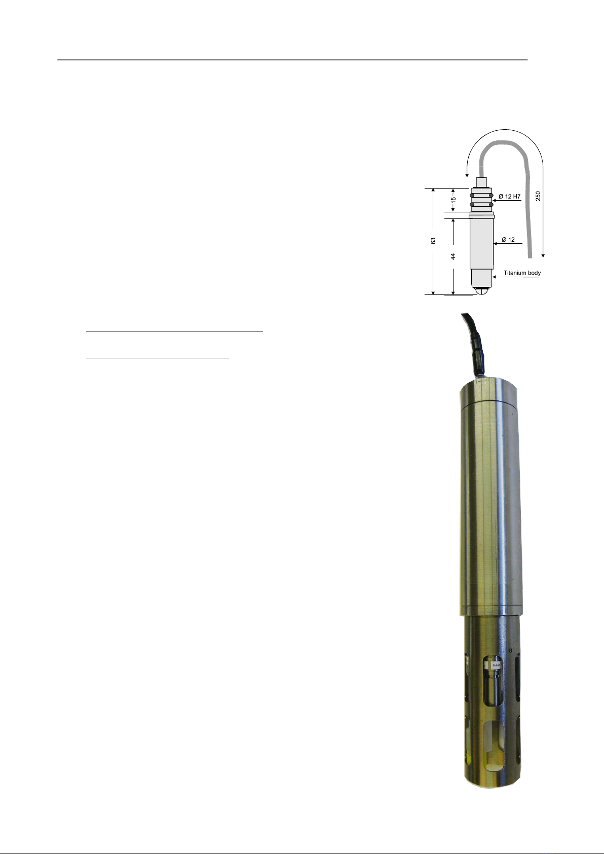
1.3.2. White POM housing - 150 bar
Measuring principle: potentiometric
pH sensor: glass membrane
Redox sensor: platinum electrode
Reference sensor: Ag/AgCl double bridge
Measuring range:
pH 3..11 pH (*)
Redox +/- 1000 mV
Accuracy: pH 0.03 pH
Redox +/- 10mV
Resolution: pH 0.01 pH
Redox +/- 2mV
Time constant: t63% < 3 s
Temperature range: -2.. +38°C
Output: pH: 0..5 VDC
Redox: 0..5 VDC (**)
Power supply: 12VDC (11..15 VDC)
Power consumption: 30 mA@12 VDC
1 - Bulkhead connector face view

OCEAN SEVEN 306 - pH and redox probe 5
IDRONAUT –Brugherio (MI) OCEAN SEVEN 306 12-2015
OCEAN SEVEN 306 - pH and redox probe 6
IDRONAUT –Brugherio (MI) OCEAN SEVEN 306 12-2015
Mechanics:
Probe housing: POMwhiteplastic,150bar(1500mdepth)
Sensor heads: titanium
Probe diameter: 75 mm
Probe length: 480 mm (including hanging rod)
Probe weight: 1,7 kg in air
0,7 Kg in water
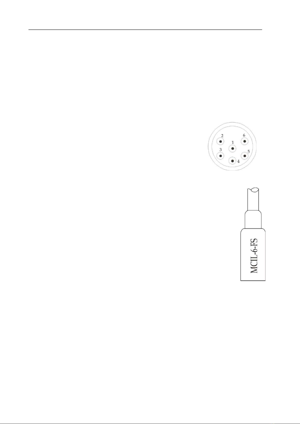
Connectors:
Bulkhead male connector: IMPULSE MCBH (WB)-6-FSTi/12”
Dummy connector: IMPULSE MCDC-6-FS
Mating female pigtail (1.8m): IMPULSE MCIL-6-FS
Bulkhead male connector pin-outs:
Pin 1: power GND
Pin 2: analogue GND
Pin 3: pH 0..5V analogue output
Pin 4: power supply 12VDC (11..15 VDC)
Pin 5: redox 0..5V analogue output
Pin 6: not connected
Pigtail (2m) female connector and wire colours:
Pin 1: black power GND
Pin 2: white analogue GND
Pin 3: red pH 0..5V analogue output.
Pin 4: green power supply 12VDC (11..15 VDC)
Pin 5: blue redox 0..5V analogue output
Pin 6: brown not connected
(*) The pH electronic range is customizable to: 0..14 pH, 2..12 or 3..11(default), see
the description in the HW schematic section.
(**) The true redox output is +/- 2000 mV. An offset of +2500mV allows the redox
sensor to operate in the positive voltage realm. Therefore the redox sensor
output is +500 mV to +4500 mV. Calculation on how to obtain Redox value are
described in a dedicated section.
Bulkhead connector face view
OCEAN SEVEN 306 - pH and redox probe 7
IDRONAUT –Brugherio (MI) OCEAN SEVEN 306 12-2015
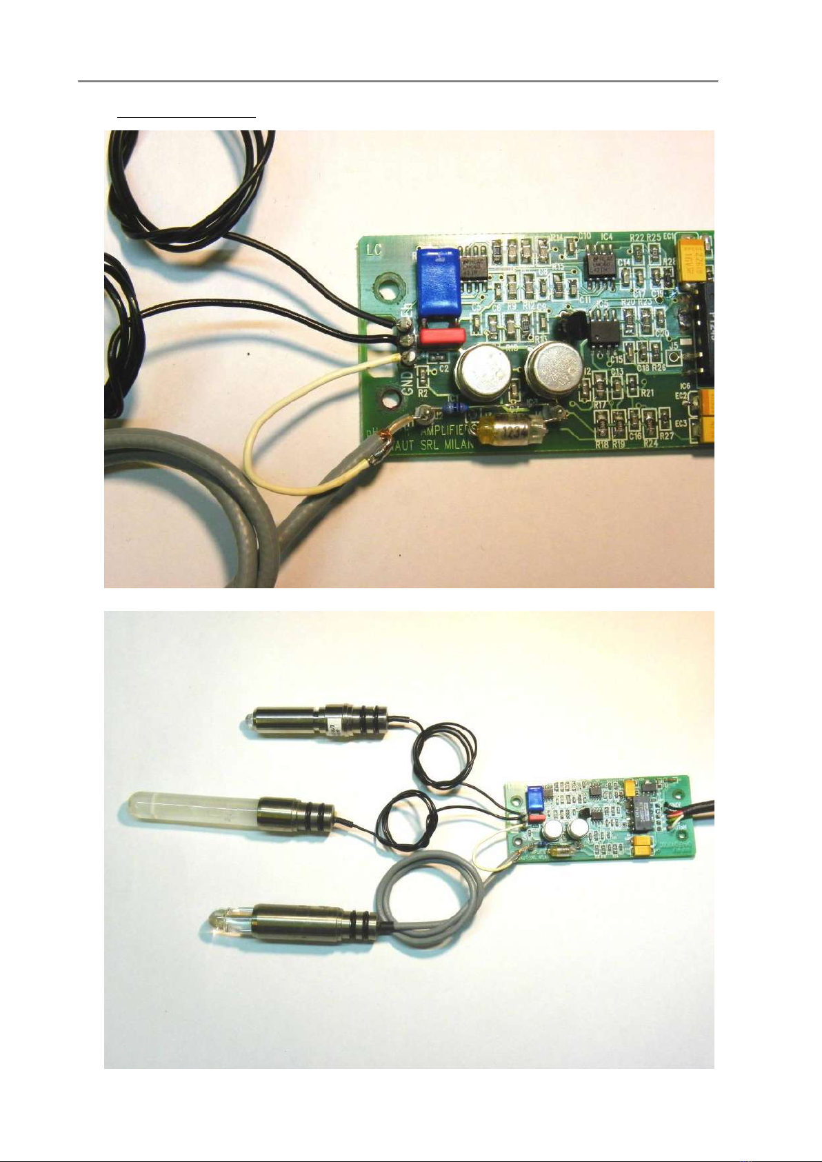
1.4. SENSOR WIRING

OCEAN SEVEN 306 - pH and redox probe 8
IDRONAUT –Brugherio (MI) OCEAN SEVEN 306 12-2015
1.5. SHIPPING LIST
OCEAN SEVEN 306 pH & redox probe 1
OCEAN SEVEN 306 Operator’s Manual 1
Female pigtail (1.8 m) 1
Reference Sensor Storage Solution 2 x 25 ml
pH 7.0 Buffer solution 1 x 100 ml
pH 4.0 Buffer 1 x 100 ml
Spare hydrating cap 2
pH calibrating tool 1
pH Sensor Etching Solution 1
tool to dismount the sensor protection cage 1
2. DAILY OPERATIONS
The OCEAN SEVEN 306 pH and reference sensors are protected by hydrating caps which prevent the
sensors from dehydration. First of all, remove the hydrating cap and soak the sensors with water. If
needed, carry out a pH sensor calibration (see calibration section) and then connect the pH & redox
probe to your CTD and power it on. The OCEAN SEVEN 306 is ready for deployment.
At the end of deployment, always protect the pH and reference sensors (when not immersed in water)
with the hydrating caps. The caps are respectively filled with the Reference Sensor Storage Solution
for the reference sensor and with distilled water for the pH sensor.
A dedicated maintenance section describes the operations to be carried out whenever the pH or redox
sensor response is not reliable due to noise or/and drift during calibration.
3. CALIBRATION
The pH sensor calibration is carried out by reading the offset value only and by using a single buffer
solution: pH7 for instance. A second buffer pH4 can be used to verify the calibration and linearity of
the OCEAN SEVEN 306 pH preamplifier.
The procedure is as follows.
Pull out the pH calibration tool from the accessory kit and fill it with the pH7 buffer solution. The
buffer cup has been designed to simultaneously fit in the pH and reference sensors and should be
placed under these sensors with the probe in its vertical position (sensors looking at the floor).
Remove the pH and reference sensor hydrating caps.
Rinse the pH and reference sensors with distilled water.
Dry both sensors to avoid dilution of the pH buffer.
Fill the calibration cup with the pH calibration buffer.
Immerse the pH and reference sensors in the calibration cup.
Fill the level of the pH buffer to allow the buffer to touch the metallic body of the pH sensor.
Wait few minutes until the measurements stabilize.
Through your CTD data acquisition circuitry and software, take note of the voltage output from
the pH sensor. The pH sensor output voltage “OFFSET”will be then used to calculate the pH
values (see the pH calculation section).
3.1. REFERENCE SENSOR QUALITY
The reference sensor is a consumable and must be replaced when exhausted or if it has been
contaminated by highly aggressive and/or polluted waters after deployment.
The quality of the reference sensor may be judged by verifying the pH output voltage during the
calibration with pH 7.0 buffer. By subtracting the voltage reading from the nominal VOUTpH7 (see
below table), it is possible to calculate the ΔV with respect to the nominal (ideal) value (see table).

OCEAN SEVEN 306 - pH and redox probe 9
IDRONAUT –Brugherio (MI) OCEAN SEVEN 306 12-2015
If the variation voltage is greater than 70% of the pH sensor slope, the reference is contaminated or
exhausted and must be replaced.
Thus:
ΔV = VOUTpH7 –Nominal VOUT
The below table resumes the maximum permitted variation voltage for each OCEAN SEVEN 306
measuring range.
Measuring range Nominal VOUT Nom. slope Max. ΔV
0..14 pH 2499 mV 352 mV 250 mV
2..12 pH 2497 mV 496 mV 350 mV
3..11 pH 2496 mV 634 mV 450 mV
Note: Nominal VOUT referred to measurement of pH buffer 7.0 !
3.2. pH BUFFER TRUE VALUE
During calibration, to obtain the maximum accuracy from the pH measurement, it is needed to correct
the pH buffer solution according to its temperature. In fact. the pH of the buffers change with the
temperature. The below table resumes the IDRONAUT pH7 (phosphate) and pH4 (phthalate) buffer
solutions of the accessories of the OCEAN SEVEN 306 probe:
Temperature (°C) pH4 pH7
0 4.00 7.12
10 4.00 7.06
20 4.00 7.02
25 4.00 7.00
30 4.01 6.99
40 4.03 6.97
50 4.05 6.96
60 4.08 6.97
70 4.12 6.98
80 4.16 7.00
90 4.21 7.03
4. pH CALCULATION AND CORRECTION
This calculation corrects the pH value, as read by the sensor, taking into account the sample
temperature at the moment of acquisition.
pH =
where:
pH VOut = sample pH VOUT in V.
Offset = pH VOUT during calibration in V.
Slope = pH slope in V. Depends on the selected pH range (see dedicated section).
Cal. Buffer = 7.0 or any Buffer value corrected in function of the temperature used
during the calibration.

OCEAN SEVEN 306 - pH and redox probe 10
IDRONAUT –Brugherio (MI) OCEAN SEVEN 306 12-2015
Temperature = Sample temperature in °C.
58.168 = Nerst constant at 20° C.
54.2 = Nerst constant at 0° C.
0.1984 = V per pH unit per °C.
The above calculation is based on the following assumption:
The NERST equation, E = E0 + 2.303 RT/nF log a, predicts the theoretical output of any electrochemical cell.
By applying this equation to the glass electrode system, it can be shown that the mV response per pH unit
varies with centigrade temperature in the following way:
0°C 54.20 mV/pH 37°C 61.53 mV/pH
25°C 59.16 mV/pH 50°C 64.12 mV/pH
30°C 60.15 mV/pH 100°C 74.04 mV/pH
The potential response of the electrode system changes 0.1984 mV per pH unit per °C.
5. REDOX CALCULATION
The true redox output is +/- 1000 mV. An offset of +2500mV allows the redox sensor to operate in the
positive voltage realm. Therefore, the redox sensor output is +1500 mV to +3500 mV.
Redox mV = (Redox VOUT mV –2500 mV) / 2.0

OCEAN SEVEN 306 - pH and redox probe 11
IDRONAUT –Brugherio (MI) OCEAN SEVEN 306 12-2015
6. MAINTENANCE
This section contains information about the maintenance procedure for the OCEAN SEVEN 306
sensor.
6.1. REFERENCE SENSOR
During all periods of non use, the reference sensor must be always hydrated with the IDRONAUT
REFERENCE SENSOR STORAGE SOLUTION or, if not available, even with a KCl saturated
solution, using its plastic hydrating cap. Fill the cap to about one third with the solution. The cap
should be squeezed in order to allow an easy insertion.
Before starting the use, the plastic hydrating cap must be removed.
If the sensor has been exposed to air without its protective cap or if the solution in the cap is not
present, the solid electrolyte of the sensor may have contracted forming internal air bubbles, in
particular in correspondence to the junction hole. In this case, it is necessary to fill the cavity with
the IDRONAUT REFERENCE SENSOR STORAGE SOLUTION. Take a small syringe, i.e. 1.5 ml
and aspirate a small amount of the IDRONAUT REFERENCE SENSOR STORAGE SOLUTION
(included in the accessories). Place the probe on a table in a horizontal position taking care that it
does not rotate. Carefully insert the needle of the syringe in the junction hole of the reference
sensor without bending the needle which can cause breaking of the glass sensor. Gently press the
syringe plunger to inject some drops of solution inside the hole to eliminate the air bubbles. If the
cavity is too big and the electrolyte added easily leaks, or should the cavity appear contaminated
by foreign material, then the replacement of the reference sensor is necessary.
If the sensor is left immersed in the measuring water sample, there is a slow progressive loss of the
KCl from the solid electrolyte. In such working conditions, the reference sensor needs to be
replaced within 6 months¸ 1 year from the beginning of the use
6.2. pH SENSOR
The glass membrane of the pH sensor must be always kept hydrated. If the sensor is stored dry for an
extended period (more than a day), the sensor’s performance may deteriorate. The electrode
sensitivity diminishes, the response times increase and signals tend to drift during measurements and
calibrations.
Before using the sensor after long storage periods, it is advisable to check the electrode performance
using pH7 and pH4 buffers. Following calibration of the sensor with pH7 buffer (see the relevant
section), wash the sensor and calibration cup with distilled water.
Then perform the following as described:
1. Dry the electrode with a soft tissue, making sure not to rub on the pH sensor tip.
2. Fill the calibration cup with pH4 buffer and dip the pH and reference electrodes in the cup.
3. Gently stir the buffer cup vertically. At an ambient temperature of 20 ±2oC, the pH reading should
be 4.00 ±0.10 pH. If the reading is outside this range, repeat the calibration at pH7 and then re-
check reading at pH4. If pH4 reading is still not within tolerance, it is necessary to reactivate the
pH sensor using the pH etching solution (included in the accessories).
Both pH7 and pH4 buffer solutions used in the cup must be thrown away and not placed in the
pH7 and pH4 bottles again. The pH7 and pH4 buffer solutions will generally last no longer than
one year after opening the bottles, as the ambient CO2 and pollutants can deteriorate with them. In
case of doubt or of bad results, use fresh pH7 and pH4 buffer solutions as, in many cases, the pH
problems are simply due to contaminated pH solutions.
6.2.1. To etch the sensor, perform the following:
Half fill the transparent cap with the pH SENSOR ETCHING SOLUTION.
Note
Use gloves to avoid any direct skin contact with the pH sensor etching solution since the solution contains
hydrofluoric acid and ammonium fluoride and is highly corrosive.
Place the cap on the pH sensor, gently squeezing the sides to limit the inclusion of air bubbles
during insertion. Take care that the etching solution covers the full round end of the sensor. After
no more than 1 minute, remove the cap and carefully rinse both the pH sensor and cap with plenty
of water. The electrode should be left in distilled water overnight before use.

OCEAN SEVEN 306 - pH and redox probe 12
IDRONAUT –Brugherio (MI) OCEAN SEVEN 306 12-2015
IMPORTANT
A. The etching solution must not be used improperly, for instance to store the electrode as this will
permanently damage its pH glass membrane . The electrodes should always be stored either in
distilled water or in the pH7 buffer solution.
B. The treatment of the pH sensor with the etching solution cannot be performed indefinitely. After
performing this step a few times, the treatment ceases to have any positive effect and the sensor
should be replaced with a new one.
C. Do not use the etching solution with the reference sensor. Permanent damage to the reference
electrode will result.
D. When not in use, the pH sensor must be fitted with the protective cap filled with either pH7
BUFFER or distilled water. (Alternatively, a salt solution - normally 3M KCl - can be used).
6.2.2. Important remark on the pH measurement
If the probe is not to be used for periods exceeding more than half a day, always place the white
plastic hydrating cap on the pH and the one on the reference sensor. The caps must be respectively
filled with pH7 Buffer Solution (or simply with clean water) and Idronaut Reference Sensor Storage
Solution (or even with KCl saturated solution). Alternatively for a short time (i.e. half a day), immerse
the probe sensor head in clean water to prevent the pH and reference sensor dehydration.
6.3. REDOX SENSOR
The redox sensor can be contaminated by fouling or if some mud accidentally covers its sensitive tip.
In this case, it is wise to clean the sensor tip before each series of measurements. Use the abrasive
paper P400 (which must be wet) only. It is sufficient to slightly rub the glass tip (where, at its centre,
the platinum wire is placed) on the abrasive surface of the paper two or three times. Wash the sensor
tip with distilled water to remove residues.

OCEAN SEVEN 306 - pH and redox probe 13
IDRONAUT –Brugherio (MI) OCEAN SEVEN 306 12-2015
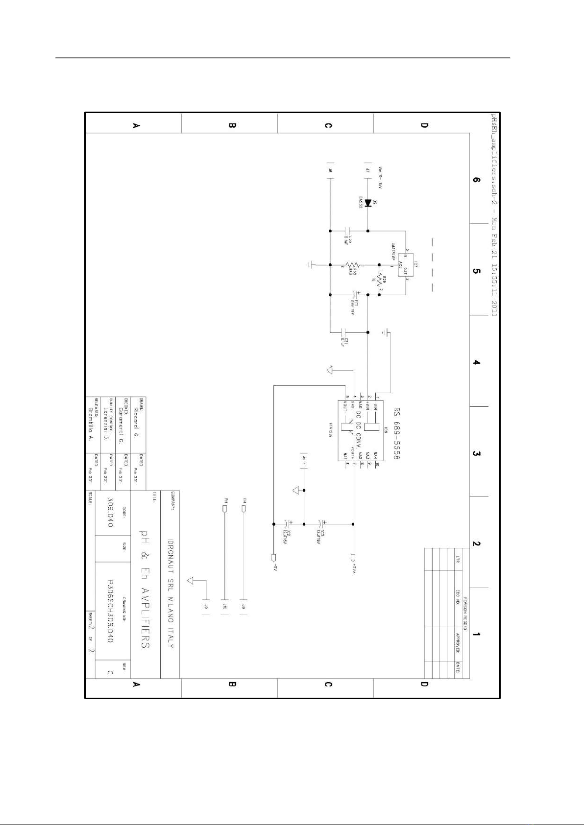
7. OCEAN SEVEN 306 –ELECTRONIC SCHEMATICS
OCEAN SEVEN 306 - pH and redox probe 14
IDRONAUT –Brugherio (MI) OCEAN SEVEN 306 12-2015

OCEAN SEVEN 306 - pH and redox probe 15
IDRONAUT –Brugherio (MI) OCEAN SEVEN 306 12-2015
7.1. CUSTOMIZATION of the pH SENSOR MEASURING RANGE
As shown in the above schematics, it is possible to modify the pH range from the standard (3..11pH)
value by replacing a single resistor “R10”. After the modification, it is mandatory to calculate the new
SLOPE factor.
7.2. DETERMINATION OF THE pH SLOPE FACTOR
The OCEAN SEVEN 306 pH electronic preamplifier is linear and therefore the SLOPE can be
calculated by using two pH buffers only.
To obtain the SLOPE, proceed as follows:
Pull out the pH calibrating tool from the accessory kit and fill it with the pH7 buffer solution. The
buffer cup has been designed to simultaneously fit in the pH and reference sensors and should be
placed under these sensors with the probe in its vertical position (sensor looking at the floor).
Remove the pH and reference sensor hydrating caps.
Rinse the pH and reference sensor using distilled water
Dry both sensors to avoid contamination of the pH buffer.
Fill the calibration cup with the pH buffer 4.0
Immerse the pH and reference sensors in the calibration cup
Fill the level of the pH buffer to allow the buffer to touch the metallic body of the pH sensor.
Wait few minutes until the readout is stable.
Take note of the pH sensor VOUT
Remove the sensors from the calibration cup.
Rinse the pH and reference sensors with distilled water.
Dry both sensors to avoid contamination of the pH buffer.
Fill the calibration cup with the pH buffer 7.0.
Immerse the pH and reference sensors in the calibration cup.
Fill the level of the pH buffer to allow the buffer to touch the metallic body of the pH sensor.
Wait few minutes until the read-out is stable.
Take note of the pH sensor VOUT.
pH SLOPE =
Table of contents
Other idronaut Measuring Instrument manuals


