IDS NXT vegas Guide
IDS NXT vegas
IDS Imaging Development Systems GmbH
Dimbacher Str. 6-8
D-74182 Obersulm, Germany
T: +49 7134 96196-0
E: info@ids-imaging.com
W: http://www.ids-nxt.com
Hardware description

2020-01-21 2
IDS NXT vegas: Hardware description
Contents
1 Preface .............................................................................................................................................. 3
2 Safety instructions ............................................................................................................................ 4
3 IDS NXT vegas .................................................................................................................................. 6
3.1 Standards and directives .............................................................................................................. 6
3.2 Ambient conditions ...................................................................................................................... 7
3.3 Notes on ambient conditions ......................................................................................................... 7
4 Mechanical data ................................................................................................................................ 8
5 System .............................................................................................................................................. 9
6 Optics ............................................................................................................................................. 10
7 Optical display ................................................................................................................................. 11
7.1 Display ..................................................................................................................................... 11
7.2 Status LEDs .............................................................................................................................. 11
7.3 Acknowledgement LED ............................................................................................................... 12
7.4 Integrated lighting ...................................................................................................................... 13
8 Acoustic display .............................................................................................................................. 14
9 Distance measurement .................................................................................................................... 15
10 Electrical data ................................................................................................................................ 16
10.1 Pin assigment Ethernet connector ............................................................................................. 16
10.2 Pin assignment I/O connector ................................................................................................... 16
10.3 Trigger input wiring/OPTO IN .................................................................................................... 17
10.4 Flash output wiring/OPTO OUT .................................................................................................. 18
10.5 RS-232 wiring .......................................................................................................................... 19
11 Setup ............................................................................................................................................. 21
12 Maintenance .................................................................................................................................. 22
Index .................................................................................................................................................. 23

2020-01-21 3
IDS NXT vegas: Hardware description
1 Preface
Introduction
IDS Imaging Development Systems GmbH has taken every possible care in preparing this manual. We
however assume no liability for the content, completeness or quality of the information contained therein. The
content of this manual is regularly updated and adapted to reflect the current status of the software. We
furthermore do not guarantee that this product will function without errors, even if the stated specifications are
adhered to.
Under no circumstances can we guarantee that a particular objective can be achieved with the purchase of
this product.
Insofar as permitted under statutory regulations, we assume no liability for direct damage, indirect damage or
damages suffered by third parties resulting from the purchase of this product. In no event shall any liability
exceed the purchase price of the product.
Please note that the content of this manual is neither part of any previous or existing agreement, promise,
representation or legal relationship, nor an alteration or amendment thereof. All obligations of IDS Imaging
Development Systems GmbH result from the respective contract of sale, which also includes the complete and
exclusively applicable warranty regulations. These contractual warranty regulations are neither extended nor
limited by the information contained in this manual. Should you require further information on this product, or
encounter specific problems that are not discussed in sufficient detail in the manual, please contact your local
dealer or system installer.
Trademarks
The IDS logo is a registered trademark of IDS Imaging Development Systems GmbH,
registered for U.S. (Reg.No. 4,513,138) and other countries.
IDS NXT and uEye are registered trademarks of IDS Imaging Development Systems
GmbH. Microsoft and Windows are trademarks or registered trademarks of Microsoft Corporation. All other
products or company names mentioned in this manual are used solely for purposes of identification or
description and may be trademarks or registered trademarks of the respective owners.
Copyright
© IDS Imaging Development Systems GmbH. All rights reserved. This manual may not be reproduced,
transmitted or translated to another language, either as a whole or in parts, without the prior written permission
of IDS Imaging Development Systems GmbH.
Status: January 2020
Contact
Visit our web site http://www.ids-nxt.com where you will find all the latest information about our software and
hardware products. Please contact your local IDS distributors for first level support in your language. For a list
of IDS distributors worldwide please go to our website http://www.ids-nxt.com.
Address
IDS Imaging Development Systems GmbH
Dimbacher Str. 6-8
D-74182 Obersulm, Germany
T
+49 7134 96196-0
E
info@ids-imaging.com
W
http://www.ids-nxt.com

2020-01-21 4
IDS NXT vegas: Hardware description
2 Safety instructions
Read carefully these safety instructions before installing and using the product. The producer is not
responsible for damages and injury, which can occur due to false handling of the product and ignoring the
safety instructions. All warranty will be spoiled in this case.
Intended use
IDS industrial cameras are to be used to capture images for visualization and image processing tasks. They
are designed for use in industrial environments. Please comply with the requirements for the proper use of this
product. Failure to do so will render the warranty void.
·
The product is not authorized for use in security relevant applications. If it used in security relevant
applications, the customer is responsible for the necessary approvals.
·
If the product is modified or changed, all approval becomes invalid. In this case, the customer is responsible
for ensuring product conformity.
·
The warranty expires if the product is improperly disassembled, reworked or repaired by the customer or a
third party and IDS Imaging Development Systems GmbH assumes no liability for defects. If you need
service, please contact the support team.
·
The product is not a toy. Operate and store out of the reach of children.
Protection against electrostatic discharge (ESD)
Board-level cameras are especially sensitive to electrostatic discharge. Make sure to avoid mechanical or
electrical damage of the printed circuit board or its connections. Wear ESD-protective clothing and observe
the rules for handling ESD-sensitive components.
·
Do not touch the printed circuit board while it is powered.
·
Always hold the board by the edges to avoid the risk of electrostatic discharge damage.
·
For optimum ESD behavior, a clearance of 4 mm from non-shielded housings must be maintained all the
way around. For shielded housings, a smaller clearance is possible.
·
Attach the board to a conductive surface using the fixing screws. If this is not possible, ensure an insulating
connection.
·
Use connecting cable with a low-resistance shield on both sides.
Installation, operation and maintenance
The product must be connected, taken into operation and maintained only by appropriately qualified
personnel. The error-free and safe operation of this product can only be ensured if it is properly transported,
stored, set up and assembled, and operated and maintained with due care. The installation, inspection,
maintenance, extension, and repair may only be done by authorized personnel.
·
Observe the specifications in the documentation when installing the product.
·
Do not subject the product to direct sunlight, moisture or shock. Note in particular the permitted IP code of
the product.
·
Only operate the product under ambient conditions for which the respective product is approved. The use
under other ambient conditions may result in damage.
·
To avoid any damage to the connectors, only mount or remove the product with the cables disconnected.
·
Lay cables in such way that no one is endangered.
·
Before starting up, check if the electrical wiring corresponds to the specifications in the documentation.
Faulty wiring (overvoltage, undervoltage) can result in a damage in the electronics.
Transport
·
Only use ESD packaging for storage and transport of ESD-sensitive components.
·
Keep packing materials like films away from children. Abuse may result in suffocation.

2020-01-21 5
IDS NXT vegas: Hardware description
Operation and power supply
The camera power supply must meet the requirements for SELV (safety extra low voltage)/LPS (limited power
source) or ES1/PS2.
WARNING! Non-approved power supplies for camera operation may cause painful or dangerous electric
shock. Serious injury or death may occur. Use a power supply that meet the requirements for SELV (safety
extra low voltage)/LPS (limited power source) or ES1/PS2.
·
In order to ensure electrical safety, we recommend using a shielded connection cable or grounding the
camera housing so that the camera housing is connected to ground via the appropriate installation.
Avis pour le Canada
Fonctionnement et alimentation électrique
L'alimentation électrique de la caméra doit être conforme aux exigences de sécurité SELV (très basse
tension de sécurité)/LPS (source à puissance limitée) ou ES1/PS2.
AVERTISSEMENT ! Avec un bloc d'alimentation non prévu pour les caméras, il existe des risques de
décharges électriques douloureuses ou dangereuses. Celles-ci peuvent provoquer des blessures graves,
voire mortelles. Utilisez un bloc d'alimentation conforme aux exigences de sécurité SELV (très basse
tension de sécurité)/LPS (source à puissance limitée) ou ES1/PS2.
·
Pour garantir la sécurité électrique, nous recommandons l'utilisation d'un câble de connexion blindé ou la
mise à la terre du boîtier de la caméra, afin que ce dernier soit relié correctement à la masse.
CAUTION! As the camera housing may get hot depending on the operating conditions there may be risk of
burns. Provide sufficient heat dissipation so that the housing temperature does not exceed 55 °C (131 °F).
NOTICE! Cameras with Power-over-Ethernet (PoE) can be supplied with voltage both from an external source
and via PoE. The camera should not be supplied through both voltage sources at once as this can irreparably
damage the camera.
Models with time-of-flight sensor
CAUTION! Class 1 laser. The accessible laser radiation is harmless under reasonably predictable conditions.
Observe the legal regulations for laser protection.
Models with integrated lightning
CAUTION! Optical radiation from visible LED light. Do not look into beam!
Correct disposal
Dispose the camera and accessories properly and separately from other types of waste to encourage
recycling of reusable materials and to protect the environment.
According to the EC Directive 2012/19/EU (WEEE) we are obliged to take back this product, distributed by us
after August 13, 2005, free of charge at the end of its useful life and to ensure it correct disposal. As this
product is exclusively for commercial use (B2B), it must not be handed over to a public disposal facility. The
product can be disposed of by specifying the date of purchase and the serial number at the following address:
IDS Imaging Development Systems GmbH
Dimbacher Str. 6-8
D-74182 Obersulm, Germany

2020-01-21 6
IDS NXT vegas: Hardware description
3 IDS NXT vegas
3.1 Standards and directives
(only valid for devices with housing)
IDS Imaging Development Systems GmbH hereby confirms that this product has been developed, designed
and manufactured in compliance with the following European directives
·
2014/30/EU: EMC - Electromagnetic compatibility
·
2011/65/EU: RoHS - Restriction of the use of certain hazardous substances in electrical and electronic
equipment
·
Regulation (EC) No. 1907/2006 concerning the Registration, Evaluation, Authorization and Restriction of
Chemicals (REACH)
·
The CE declaration of conformity is available on the IDS website.
If the product is modified or changed all approval becomes invalid. In this case the customer is responsible for
ensuring product conformity.
Product type
IDS NXT vegas
Information for CE
EMC specifications
EN 61000-6-2
EN 61000-6-4*
Information for USA
This equipment has been tested and found to comply
with part 15 of the FCC Rules.
Class A
Information for Canada
Renseignements pour le Canada
CAN ICES-3 (A)/NMB-3(A)
Information for UL
To be compliant with the UL safety criteria GigE
cameras must be operated with indoor networks only.
UL 62368-1
CAN/CSA C22.2 No. 62368-1-14
Further information
-
* Cameras are intended exclusively for use in industrial environments.
For customers in the USA
For a class A digital device:
This equipment has been tested and found to comply with the limits for a Class A digital device, pursuant to
part 15 of the FCC Rules. These limits are designed to provide reasonable protection against harmful
interference when the equipment is operated in a commercial environment. This equipment generates, uses,
and can radiate radio frequency energy and, if not installed and used in accordance with the instruction
manual, may cause harmful interference to radio communications. Operation of this equipment in a residential
area is likely to cause harmful interference in which case the user will be required to correct the interference
at his own expense.
Name of Responsible Party
IDS Imaging Development Systems, Inc.
92 Montvale Ave., Ste 2800
Stoneham, MA 02180
U.S.A.
T: +1 781 787 0048

2020-01-21 7
IDS NXT vegas: Hardware description
3.2 Ambient conditions
Ambient temperature during operation
0 °C … +45 °C
+32 °F … +113 °F
Ambient temperature during storage
-20 °C .... +70 °C
-4 °F … +158 °F
Relative humidity*
20 % … < 100 %, non-condensing
Non-condensing means that the relative air humidity must be
below 100 %. Otherwise, moisture will form on the device
surface.
Vibration and shock resistance
Complies with DIN EN 60068-2-6 and DIN EN 60068-2-27
* Only if IP65 cables are used. Not used electrical connections must be closed with fixed covering caps.
3.3 Notes on ambient conditions
·
Avoid high air humidity levels and rapid temperature changes when using IDS NXT vision app-based
sensors.
·
Temperatures below +4 °C (+39 °F) combined with excessive relative air humidity levels can cause icing.
Provide sufficient heat dissipation so that the specified device temperature is not exceeded during operation.
In general, the following recommendations apply:
·
For a passive heat dissipation, mount the IDS NXT vision app-based sensor on a thermally-conductive
surface like a metal plate or a heat sink.
·
If necessary, provide an active cooling for example by means of a fan.
With increasing device temperatures, the image quality could be reduced due to thermal noise. It is
recommended to mount the IDS NXT vision app-based sensor to a heat-dissipating unit even if the device is
operated below the maximum specified temperature.
2020-01-21 8
IDS NXT vegas: Hardware description
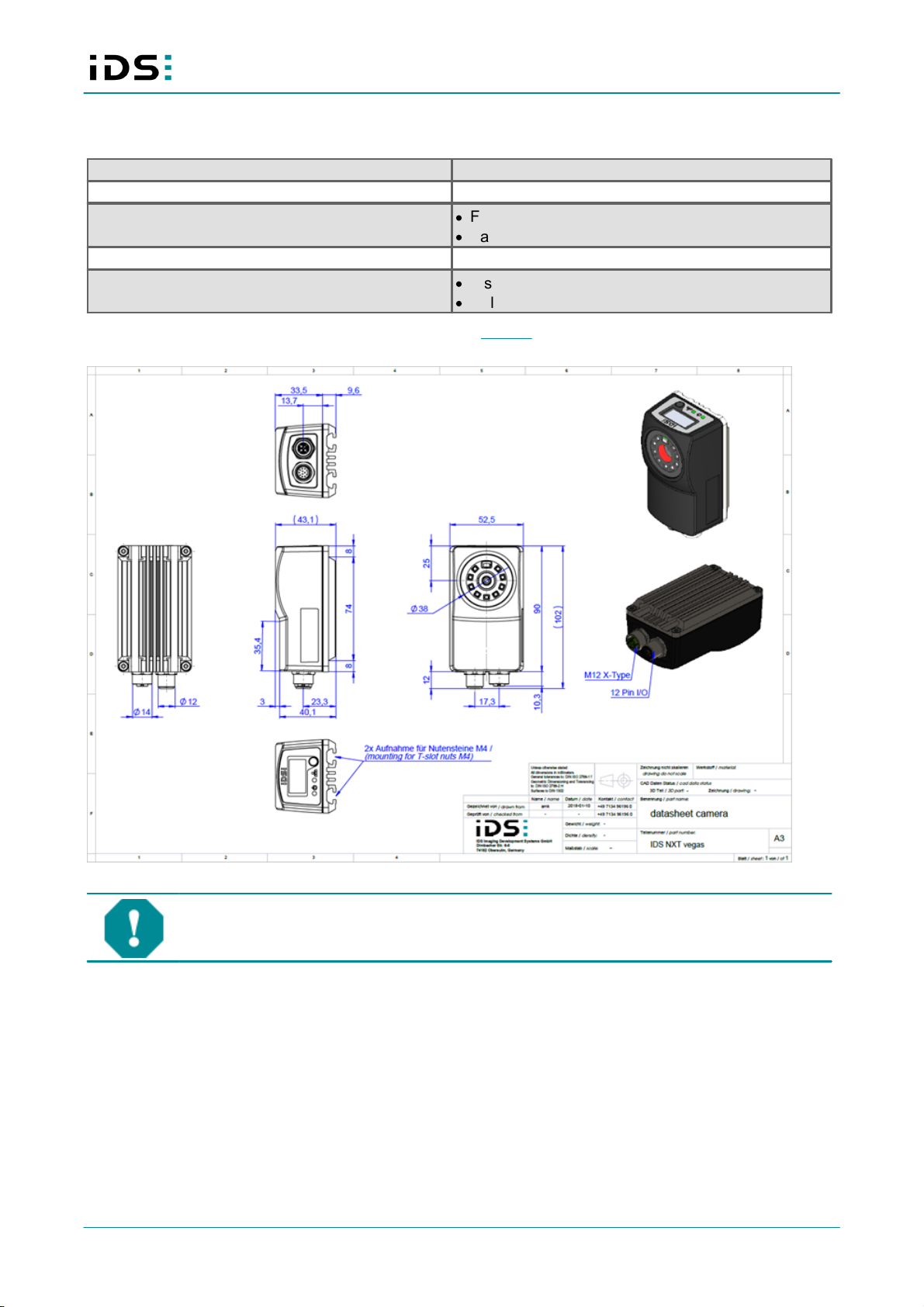
4 Mechanical data
Dimensions height x width x depth
90 mm x 52.5 mm x 43.1 mm
Weight
185 g
Material
·
Front: Plastic ABS
·
Back: Aluminum
Protection class
IP65
Mounting
·
T-slot nuts in the back, M4
·
2 slot profiles with distance 28 mm
The mechanical data for each model can be found on our website directly at the respective model beneath in
the "Downloads" tab.
IDS NXT vegas
NOTICE! The camera connectors may be damaged if you install or remove the camera with
plugged in cables. Therefore, first unplug the GigE and/or I/O cable from the camera.

2020-01-21 9
IDS NXT vegas: Hardware description
5 System
CPU
·
Xilinx Zynq Z7010
·
Dual Core ARM Cortex A9
·
667 MHz
·
Double Precision Floating Point Unit
RAM
·
DDR3
·
512 MByte
Flash
1 GByte for error images, system logs, user settings, Vision
Apps
System time
·
RTC buffered
·
Support of NTP
Operating system
Linux
Image processing
·
GE18013C HALCON / GE18013M HALCON: HALCON 13
Embedded
·
GE18013C / GE18013M: -

2020-01-21 10
IDS NXT vegas: Hardware description
6 Optics
Optics
M12, liquid lens
Focal length
9.6 mm
Aperture (F)
F3.7
Focus
Vari-focus
Focus range
7 cm … 200 cm

2020-01-21 11
IDS NXT vegas: Hardware description
7 Optical display
7.1 Display
The IDS NXT vegas has a display that provides information about the device and the network.
IDS NXT vegas display
·
OLED display
·
128 x 64 pixels
·
Monochrome (yellow)
·
0.96“ diagonal
·
160° viewing angle
·
Contrast 2000:1
·
1x Pushbutton for operation
NOTICE! Pointed objects can damage the pushbutton. Do not use a pointed object to operate
the pushbutton.
You can call up the following device information via the pushbutton on the display:
·
Device temperature (in Celsius)
·
CPU load (in percent)
·
Date
·
Model name
·
Serial number of the device
·
Firmware version
·
Hardware revision
·
Network mode
·
IP address of the device
·
MAC address of the device
7.2 Status LEDs
The IDS NXT vegas has 2 LEDs (two-color: red and green) for status indication of the power supply and the
network.

2020-01-21 12
IDS NXT vegas: Hardware description
(1) LED "Power"
(2) LED "Network"
LED "Power"
LED
Function
Description
Off
Device is off
No supply voltage
Flashes green
Device OK,
Initialization phase
Operating system is booted, self-test running
Lights green
Device OK
Self-test successful, device ready for operation
Lights orange
Device OK,
service operation
The device is configured, e. g. when the firmware is updated or
in the training mode of the code reading app.
Flashes green
Image acquisition
Permanent green light, briefly 1/10 s per second off during
image acquisition
Flashes red
Failsafe
Device cannot start, maintenance necessary
LED "Network"
LED
Function
Description
Off
Network not OK
No network connected
Flashes green
Network OK
Data transfer running
Lights green
Network OK
Device is ready for operation
Lights orange
DHCP
Device obtains IP address via DHCP
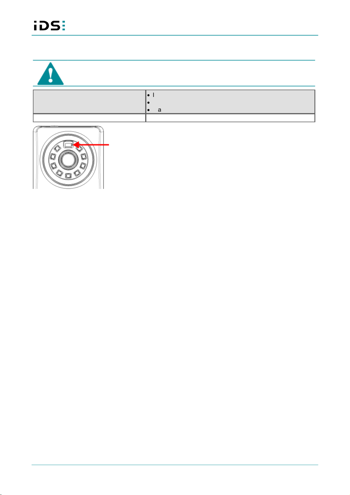
7.3 Acknowledgement LED
CAUTION! Optical radiation from visible LED light. Do not look into beam!
The IDS NXT vegas has an acknowledgement LED, which gives optical feedback when image processing is
successful.
·
1x LED
·
114 mW
·
Light color green
·
λ = 525 nm ±10 nm
·
Switch on/off

2020-01-21 13
IDS NXT vegas: Hardware description
Acknowledgement LED
7.4 Integrated lighting
CAUTION! Optical radiation from visible LED light. Do not look into beam!
The IDS NXT vegas has an integrated LED lighting besitzt eine integrierte LED-Beleuchtung, which can be
additionally activated.
Monochrome version rev. 1.2
Color version rev. 1.2
8 LEDs
8 LEDs
240 mW per LED
285 mW per LED
Light color red
Light color white
λ = 623 nm ±16 nm
5000 K
Switch on/off
Switch on/off
Integrated lighting

2020-01-21 14
IDS NXT vegas: Hardware description
8 Acoustic display
The IDS NXT vegas has an acoustic indicator (beeper) for event messages:
·
1 kHz … 4 kHz
·
Switch on/off
The following events can be signalized: image processing OK, image processing errors, device errors
2020-01-21 15
IDS NXT vegas: Hardware description
9 Distance measurement
CAUTION! Class 1 laser
The accessible laser radiation is harmless under reasonably predictable conditions. Observe
the legal regulations for laser protection.
ToF sensor
·
IR laser for distance measurement
·
λ = 940 nm
·
Class 1 laser
Measuring range
7 cm … 100 cm
Sensor for distance measurement
2020-01-21 16
IDS NXT vegas: Hardware description
10 Electrical data
10.1 Pin assigment Ethernet connector
8-pin M12 connector (MMT361A315)
Pin
Description
Designation
1000BASE-T
Designation 100BASE-
T
Ethernet connector,
camera view
1
MDX0+
BI_DA+
TX+
2
MDX0-
BI_DA-
TX-
3
MDX1+
BI_DB+
RX+
4
MDX1-
BI_DB-
RX-
5
MDX3+
BI_DD+
6
MDX3-
BI_DD-
7
MDX2+
BI_DC-
8
MDX2-
BI_DC+
The M12 connector complies with the IEC/PAS 61076-2-109 standard.
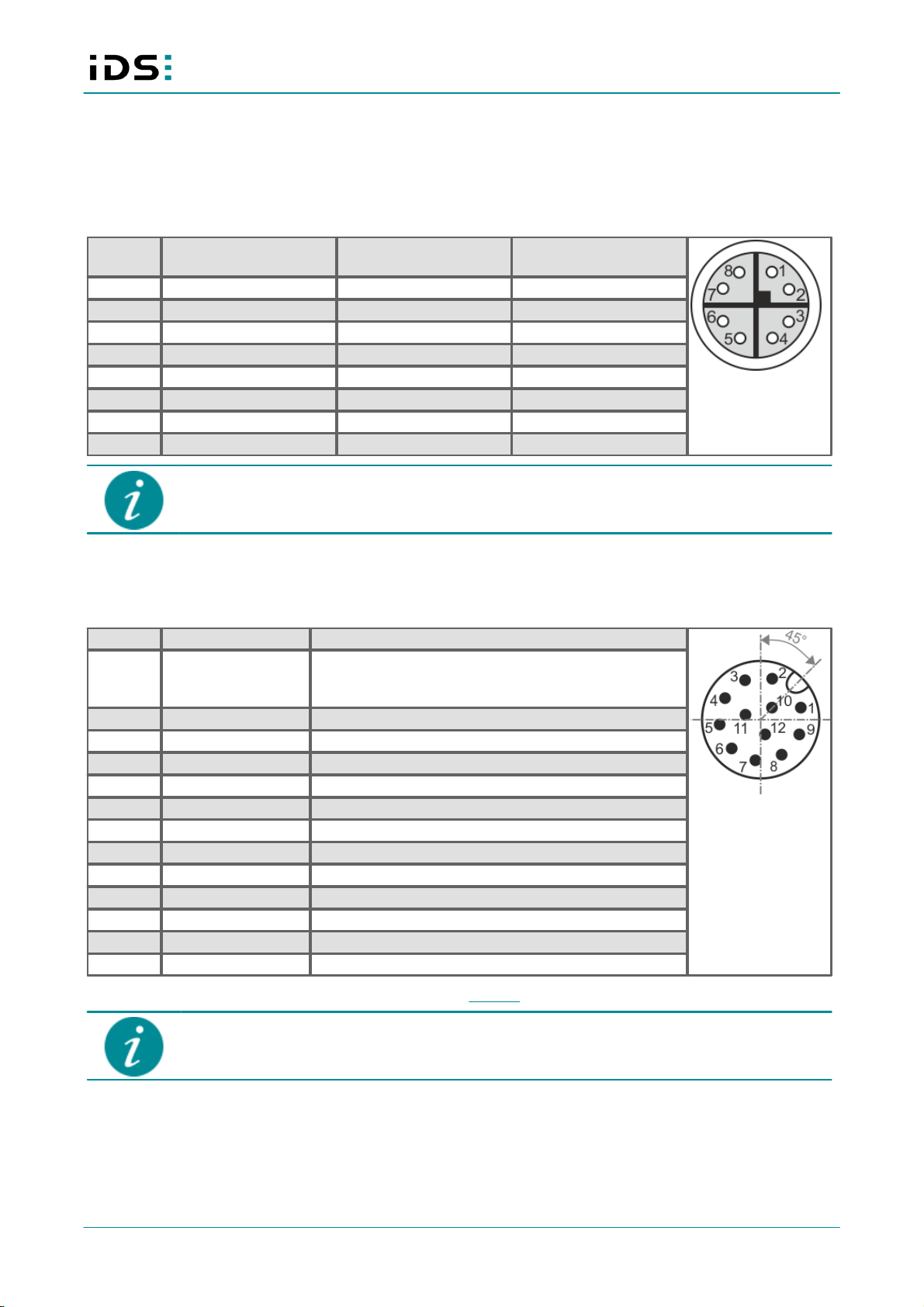
10.2 Pin assignment I/O connector
12-pin M12 connector (Attend 216A-12MSR)
Pin
Signal
Description
I/O connector, camera
view
1
VBUS
Power supply
Monochrome version: 12-24 V DC +20 %
Color version: 15-24 V DC +20 %
2
VBUS GND
Reference level (ground) for power supply and RS-232
3
Opto IN (0)
Trigger input with optocoupler
4
Opto IN (1)
Input 1 with optocoupler
5
Opto IN (COM)
Reference level for all Opto IN
6
Opto OUT (COM)
Reference level for all Opto OUT
7
Opto OUT (1)
Output 1 with optocoupler
8
Opto OUT (2)
Output 2 with optocoupler
9
RS232 (RX)
Serial interface
10
RS232 (TX)
Serial interface
11
Opto IN (2)
Input 2 with optocoupler
12
Opto OUT (0)
Flash output with optocoupler
Shield
Shield
Shield
You can check the color assignment of the cable on the website directly at the specific accessory item.
The maximum length of the I/O cable is 30 m. The cable must be shielded.
2020-01-21 17
IDS NXT vegas: Hardware description
Power supply
Monochrome version
Color version
Voltage
12-24 V DC
15-24 V DC
Tolerance
+20 %
+20 %
Residual ripple
120 mVpp
120 mVpp
IDS Imaging Development Systems GmbH recommends to adjust the power supply to the power requirement
of the camera to limit overheating in case of short circuit. To ensure electrical safety, the power supply must
meet the requirements for SELV (safety extra low voltage)/LPS (limited power source) or ES1/PS2.
Avis pour le Canada:
IDS Imaging Development Systems GmbH recommande d'adapter l'alimentation électrique aux besoins de
la caméra afin de limiter la surchauffe en cas de court-circuit. Pour garantir la sécurité électrique,
l'alimentation doit être conforme aux exigences de sécurité SELV (très basse tension de sécurité)/LPS
(source à puissance limitée) ou ES1/PS2.
Information on the power consumption of individual camera models can be found in the model data sheet.
Please keep in mind that a voltage drop will occur when you use long cables for power supply to the device.
Choose the size of the cable in such a way that the supply voltage available at the input of the device is at least
12 V (monochrome version) or 15 V (color version).
10.3 Trigger input wiring/OPTO IN
Symbol
Minimum
Typical
Maximum
Unit
Input low range
VIL
0
0
1
V
Input high range
VIH
5
-
24
V
Voltage range
0
-
30
V
Input leakage current
II
-
-
-
µ A
Trigger edge steepness
35
-
-
V/ms
Trigger pulse width (edge)
10
-
-
µ s
For interpreting the trigger signal, either the rising or the falling edge can be used. The digital inputs are
galvanically isolated using optocouplers to protect the device and the PC against surges. Only DC voltages
may be applied to the digital inputs.

2020-01-21 18
IDS NXT vegas: Hardware description
Schematic drawing
Trigger input wiring/OPTO IN
Pin 5 is the reference level (GND) for all inputs. All three inputs can also be used with different voltages.
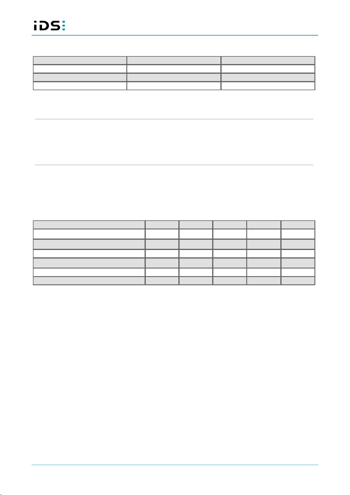
10.4 Flash output wiring/OPTO OUT
Symbol
Minimum
Typical
Maximum
Unit
Recommended supply voltage
VCC
-
-
30
V
Collector-emitter saturation voltage
VCE(SAT)
0.03
-
0.15
V
Collector-emitter breakdown voltage
V(BR)CE
100
-
-
V
Collector current continuous
IC
-
-
150
mA
The digital outputs are galvanically isolated using optocouplers to protect the device and the PC against
surges. Only DC voltages may be applied to the digital outputs.
The output of the optocoupler can be used as an open collector or open emitter output. This means that the
output signal can be connected to ground or to the supply voltage. The output signal is active if the collector-
emitter switch is closed.
2020-01-21 19
IDS NXT vegas: Hardware description
Schematic drawing open collector
Wiring as open collector
Pin 6 is the reference level (GND) for all outputs. All three outputs can be connected simultaneously as open
collector.
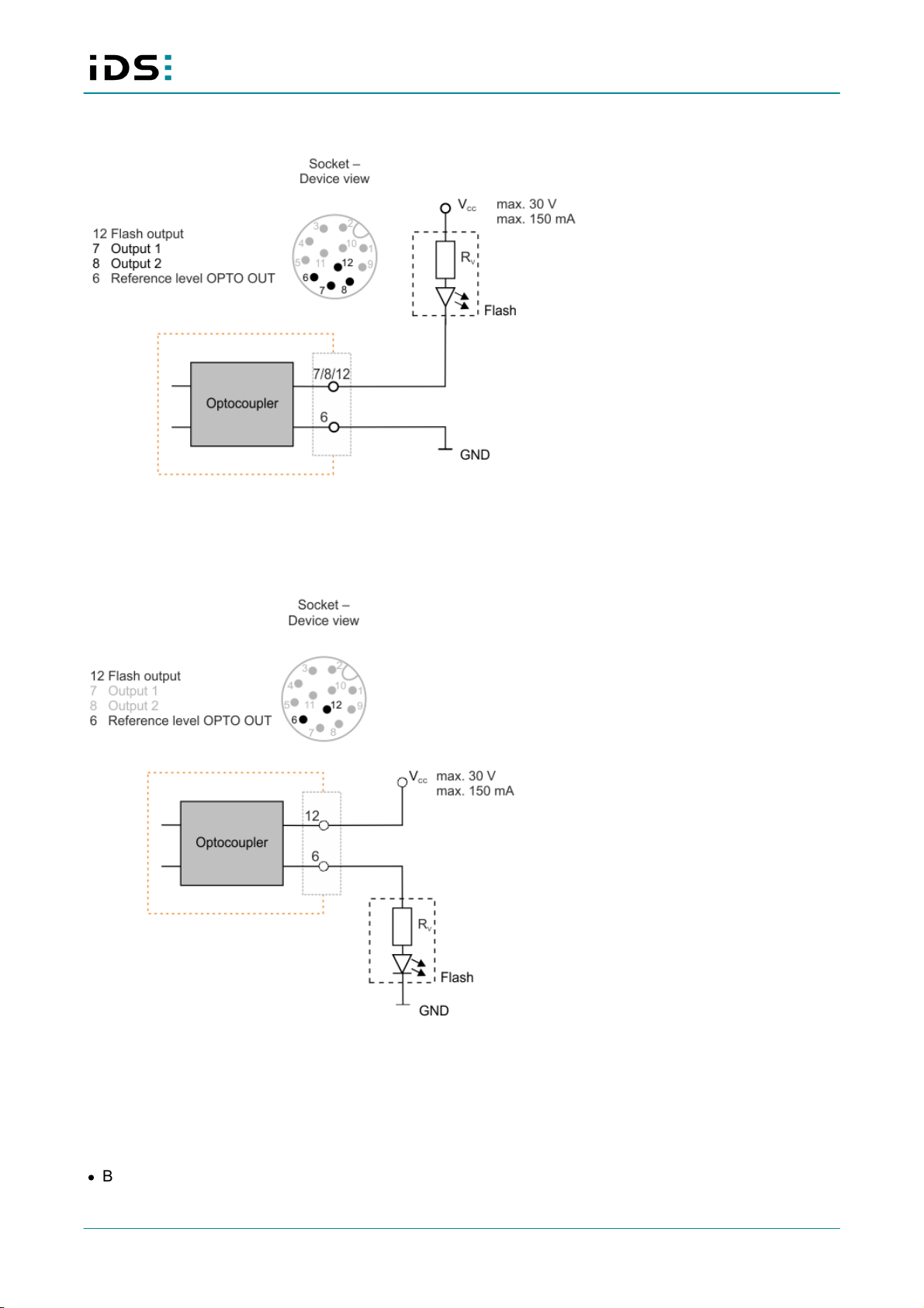
Schematic drawing open emitter
Wiring as open emitter
Only one output can be connected as an open emitter, since the load is on pin 6. The other outputs cannot be
used anymore.
10.5 RS-232 wiring
The IDS NXT vegas has a serial interface of the type RS-232:
·
Baud rate: 300 … 230 400 Baud

2020-01-21 20
IDS NXT vegas: Hardware description
·
Input voltage: max. ±15 V
·
Output voltage: -5,7 V to +6.2 V
·
Data rate: max. 250 kbps
·
Compatible with TIA/EIA-232-F standard
·
Permissible range according to RS-232 from ±3 V to ±15 V
The data rate of the serial interface depends on the capacity and length of the cable.
Other manuals for NXT vegas
2
Table of contents
Other IDS Accessories manuals


Popular Accessories manuals by other brands


Olimpia splendid
Olimpia splendid PELER 1 Instructions for use and maintenance

Vega
Vega VEGAPULS 65 Quick setup guide

Malmet
Malmet Energy Saver ES910 Operation, maintenance and installation manual

AMX
AMX Rough-In Box CB-TP7 installation guide

Philips
Philips SVC2235/27 Instructions for use

Outdoor Revolution
Outdoor Revolution CompactAirLite 420 Instructions & care manual