iDVTEL DVTel 9840 Series User manual

M9831A, August 05
DVTel 9840 Series IP Dome
Installation Manual

2
Table of Contents
PREFACE..................................................................................................................................................... 3
ENCODER CONFIGURATION ................................................................................................................ 4
PHYSICAL INSTALLATION.................................................................................................................... 6
INDOOR DOME INSTALLATION.................................................................................................................... 6
OUTDOOR DOME INSTALLATION ................................................................................................................ 8
CAMERA CONFIGURATION ................................................................................................................ 10
DOME SETUP IN LATITUDE ....................................................................................................................... 10
Configuring the Camera...................................................................................................................... 10
Configuring the Serial Port and PTZ Motor .......................................................................................12
Creating Presets and Patterns.............................................................................................................. 13
DOME MENU SETUP ................................................................................................................................. 14
Camera Information Setup.................................................................................................................. 14
Camera Settings Setup........................................................................................................................ 15
Exposure Mode Setup......................................................................................................................... 15
On-Screen Display Setup.................................................................................................................... 16
Home Position Setup........................................................................................................................... 18
Autopan Setup..................................................................................................................................... 18
Area Setup........................................................................................................................................... 19
Default Set .......................................................................................................................................... 21

3
Preface
The DVTel 9840 Series of Internet Protocol (IP) Pan-Tilt-Zoom (PTZ) Domes feature a
variety of PAL and NTSC models for both indoor and outdoor use.
The domes contain a built-in MPEG-4 encoder that converts analog video into one or two
MPEG-4 streams. The latter option is used to support viewing and recording at different
qualities (up to 4CIF, 30 ips NTSC or 25 ips PAL). The domes are powered using 24 VAC
current, delivered either through a Power over Ethernet (PoE) wiring accessory or directly.
PoE is not available for outdoor domes. Each dome also contains DIP switches for setting
the PTZ number, baud rate and protocol.
The DVTel Domes are designed to integrate seamlessly with Latitude NVMS. Most of the
devices’ configuration is typically performed through the Latitude AdminCenter.
Dome setup involves three principal tasks: encoder configuration, physical installation and
camera configuration.
The diagram below shows the dome’s dimensions, in millimeters.
265
R76
70
245
150
162
AA View
15
40
50
240
O218O
57O
O60
4- 6.5Through
Evenly Distributing
O
85O100O
Figure 1 - The DVTel IP Dome

4
Encoder Configuration
The dome’s built-in encoder should be configured in a lab before the camera is installed in
the field.
1. Power up your dome and connect it to a network switch on the same local area network as the
Latitude system.
2. Launch AdminCenter and click the Directory (globe) icon in the Selection View Pane.
Switch to the
Discovery
tab in the Configuration Pane.
Figure 2 - The AdminCenter-embedded Discovery Tool
3. Choose
VSIP
from the
Discover
drop-down menu and enter the beginning and ending
VSIP ports through which the system should search. VSIP domes’ default port is 5510
but if your unit’s port has been changed in the past use a low start value and high stop
value as your discovery parameters. Click the “binoculars” button to begin searching.
4. Your dome will appear as a unit of type “unknown” if it is new or its built-in encoder
has recently been rebooted. Otherwise, it will be listed as a camera (encoder). Right click
the dome and choose
Change IP Address…
Give the unit an IP address in the same IP
scheme as your Latitude system and leave the
Subnet mask
and
Gateway
unchanged
unless advised otherwise by your network administrator.
Figure 3 – Changing a Unit’s IP Address

5
5. To change the dome’s VSIP port, rediscover the unit and then right click it and choose
Change Port…
Enter a new port number in the
Change Port
dialog box and click
OK
.
The dome’s port should match one of its intended Media Archiver’s VSIP extensions.
You can add a VSIP extension to an Archiver through the Resource Administration
Tool (RAT) by right clicking
Archiver
in the
Resources
tree and choosing
Create>VSIP
Extension
. Note that unless your system supports Fail-Over or Redundant Archiving, you
should never create the same VSIP Extension on multiple Media Archivers.
6
Physical Installation
The following instructions present the procedure for installing a bracket-mounted IP dome
using a pendant mount. Mounts are also available for installing the dome on a wall, corner,
roof or pole. The ceiling-mounted dome requires that a round hole be made in the ceiling tile.
Indoor Dome Installation
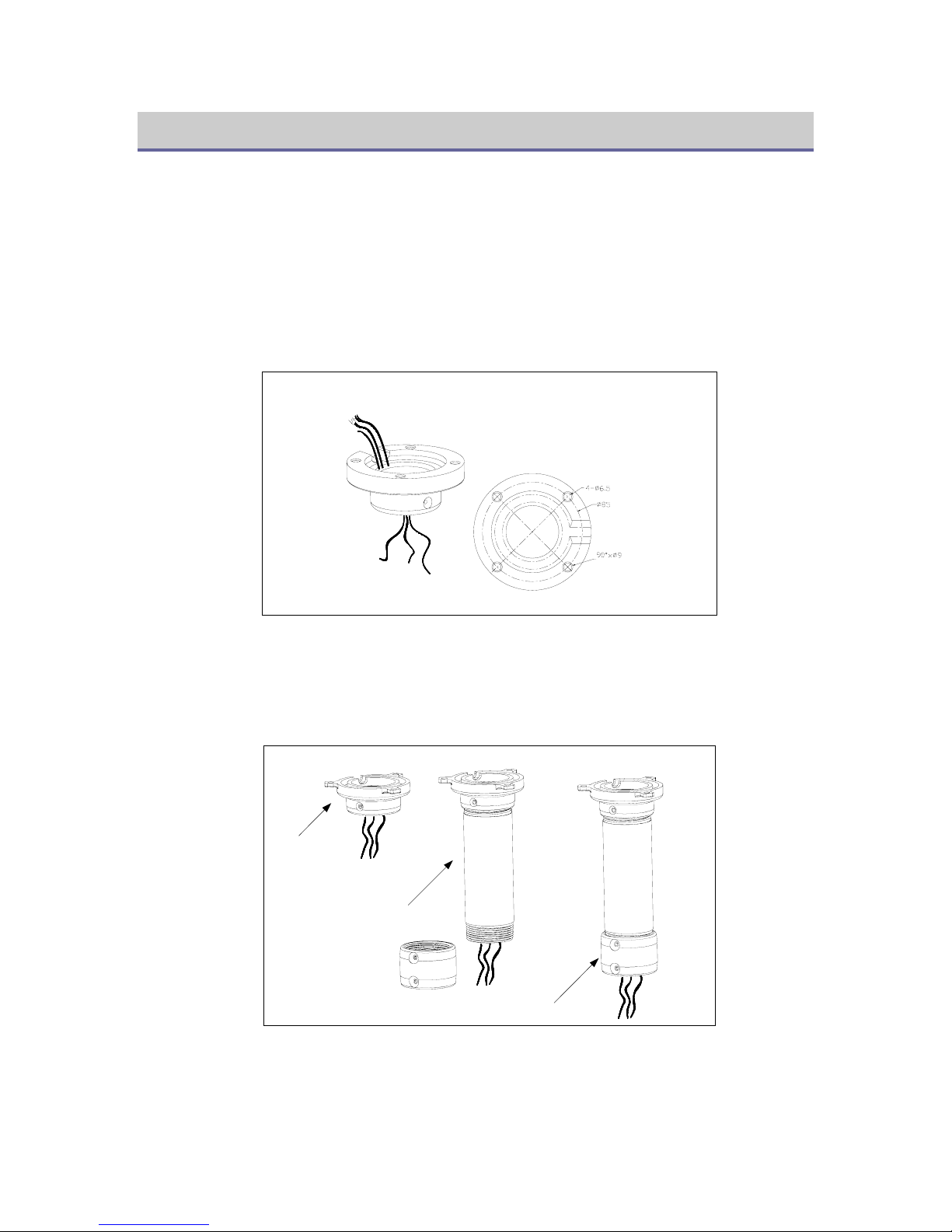
1. Place the pendant mount base against a firm ceiling and secure it with three expansion
bolts. Pull the wiring through the base hole.
Through,Everage
Bottom
Figure 4 - Installing the Mount Base
2. Screw the suspender into the pendant mount base, and then the housing holder into the
suspender. Secure the connections with holding screws and pull the wiring through the
three connected accessories.
Pendant Mount
Base
Suspender
Housing Holder
Figure 5 - Installing a Suspender and Housing Holder
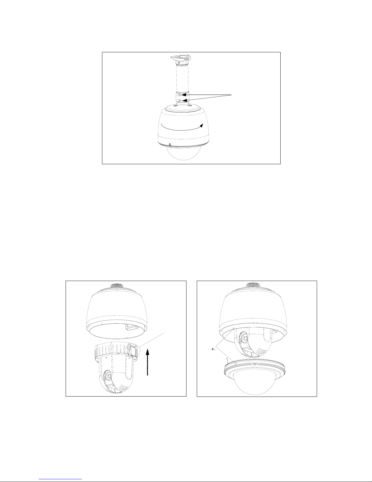
3. Screw the housing onto the housing holder and secure the connection with two holding
screws.
7
Holding Screws
Figure 6 - Installing the Housing
4. Connect your dome to power using either its power leads or the PoE wiring accessory
and a CAT5 cable of no more than 220 feet, depending on your model.
5. Connect the dome or PoE wiring accessory, depending on your model, to the network.
6. The dome’s PTZ number is set with the S1 DIP switch at the back of the dome drive.
DVTel recommends you leave at its default of 1. If you would like to change it, use the
key provided on the sticker below the S1 switch.
7. Insert the dome drive into the housing, making sure to align the red and green clasps
with the markings inside the housing (to release the dome drive, press the clasps inward).
8. To install the dome cover, line up its screws with the corresponding holes in the dome
housing, and secure the cover with the supplied pan-head screws.
tap
Figure 7 - Installing the Dome Drive
Figure 8 - Installing the Dome Cover
9. Power on the dome. Once it completes its initialization process, it can be programmed.
8
Outdoor Dome Installation
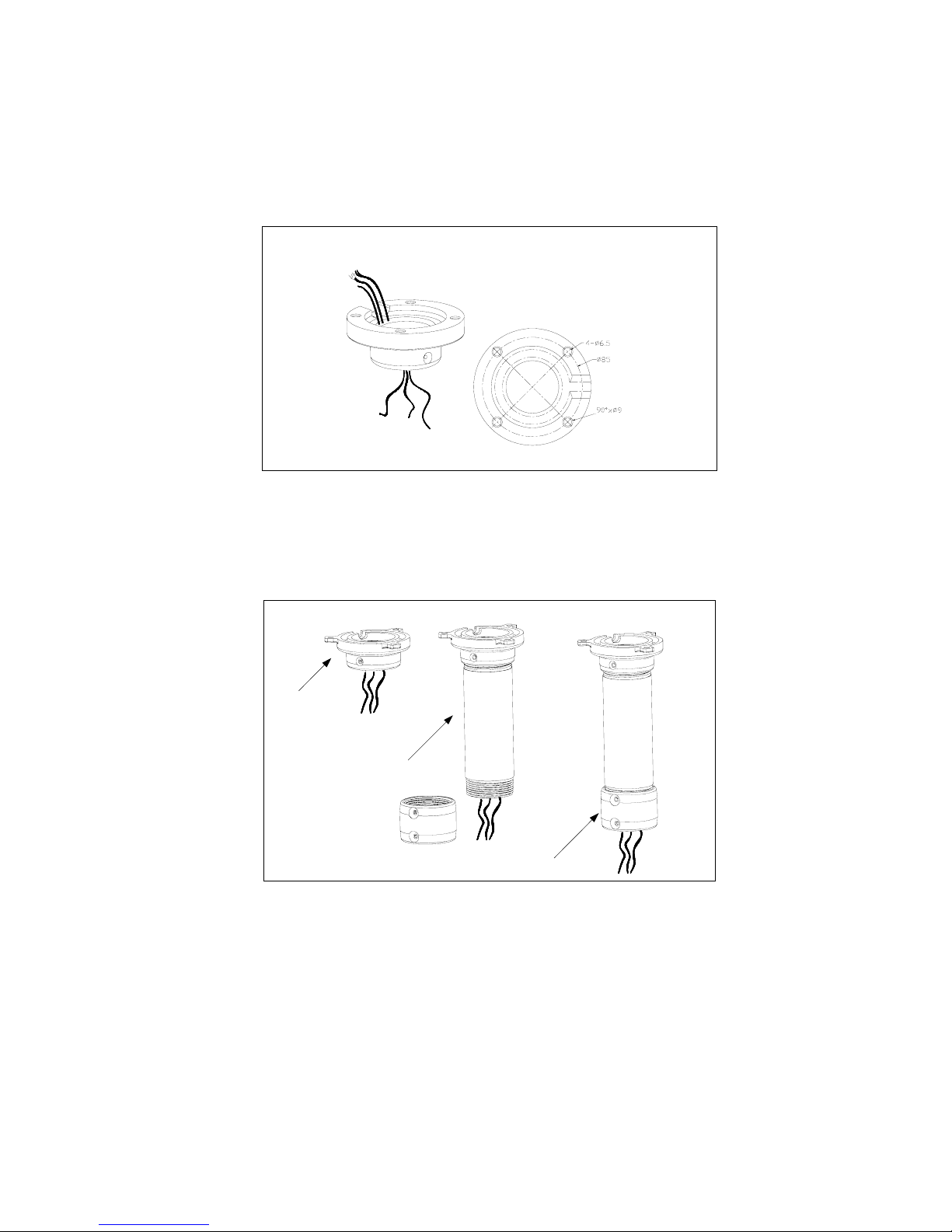
1. Place the pendant mount base against a firm ceiling and secure it with three expansion
bolts. Pull the wiring through the base hole.
Through,Everage
Bottom
Figure 9 - Installing the Mount Base
2. Screw the suspender into the pendant mount base, and then the housing holder into the
suspender. Secure the connections with holding screws and pull the wiring through the
three connected accessories.
Pendant Mount
Base
Suspender
Housing Holder
Figure 10 - Installing a Suspender and Housing Holder
3. Screw the housing onto the housing holder and secure the connection with two holding
screws. You may also want to apply thread compound to the threads on the housing.

9
Holding Screws
Figure 11 - Installing the Housing
4. Connect the dome to your network using a CAT5 cable.
5. Connect the dome to a 24 VAC power source. Do not use Power over Ethernet to power the
outdoor dome.
6. The dome’s PTZ number is set with the S1 DIP switch at the back of the dome drive.
DVTel recommends you leave at its default of 1. If you would like to change it, use the
key provided on the sticker below the S1 switch.
7. Insert the dome drive into the housing, making sure to align the red and green clasps
with the markings inside the housing (to release the dome drive, press the clasps inward).
8. To install the dome cover, line up its screws with the corresponding holes in the dome
housing, and secure the cover with the supplied pan-head screws (if your dome’s cover
comes with a heater, make sure to plug it in before affixing it to the housing).
tap
Figure 12 - Installing the Dome Drive
Figure 13 - Installing the Dome Cover
10. Power on the dome. Once it completes its initialization process, it can be programmed.

10
Camera Configuration
The DVTel IP Dome is typically configured using Latitude AdminCenter. Some of its most
common functions, such as presets and patterns, can be set-up using the system’s Graphical
User Interface (GUI). To set up most functions, however, the camera’s textual menu must
be utilized. Before this menu can be accessed from Latitude, however, the PTZ must be set
up in AdminCenter.
Dome Setup in Latitude
Setting up a dome in Latitude involves the configuration of the camera, the encoder’s serial
port, and of the PTZ motor.
Configuring the Camera
1. In the System View Pane (
Logical
view), browse for the dome. If it has yet to be
configured, its name should be based on the IP address assigned to it, followed by the
suffix “– Enc”.
Figure 14 - The General Settings Tab of the Camera Configuration Pane
2. Choose whether to use a single stream for both recording and viewing or two separate
ones and define viewing and recording qualities for each of your applicable coverages. Use
the
+
button to add a quality setting for a coverage and the
X
button to delete one. To
obtain an overview of all the coverages associated with the camera, click the “pie chart”
button. Click
Apply changes
when done.
3. Switch to the
Recording
tab to specify additional recording parameters such as storage
duration, pre- and post-alarms and archiving schedules. Click
Apply changes
.

11
Figure 15 - The Recording Tab of the Camera Configuration Pane
4. Use the
Dynamic recording
tab to specify two additional, optional sets of recording
quality parameters for manual and event-based recording. Click
Apply changes
.
Figure 16 - The Dynamic Recording Tab of the Camera Configuration Pane
5. Switch to the
Attributes
(second to last) tab and make sure the
Analog format
is set to
the correct option for your device (either
PAL
or
NTSC
). Click
Apply changes
.
6. In the View Selection Pane, drag and drop your camera into an appropriate site (you can
create one by right clicking anywhere in the pane and choosing
Create>Site
).

12
Configuring the Serial Port and PTZ Motor
1. In the
Physical
view of the System View Pane, browse for the dome encoder’s serial
port (both the serial port and the camera appear under the unit in the tree hierarchy).
Figure 17 - The Serial Port Configuration Pane
2. Change
Data bits
to
8
,
Parity
to
None
,
Stop bits
to
1
,
Baud rate
to
4800
, and
Line
Driver
to
RS422/485
. Click
Apply changes
.
3. Right click anywhere in the System View Pane and choose
Create > PTZ…
Figure 18 – The
Create PTZ
Dialogue Box
13
4. Browse for the dome in the
Select video encoder
window and click the
Serial port(s)
on the same unit
radio button if it is not already selected.
5. Choose
DVTel IP
from the
Protocol
drop-down menu and click
OK
.
6. Change the
PTZ number
field (under the PTZ motor
Properties
tab) to the dome’s
PTZ number (typically
1
) and click
Apply changes
.
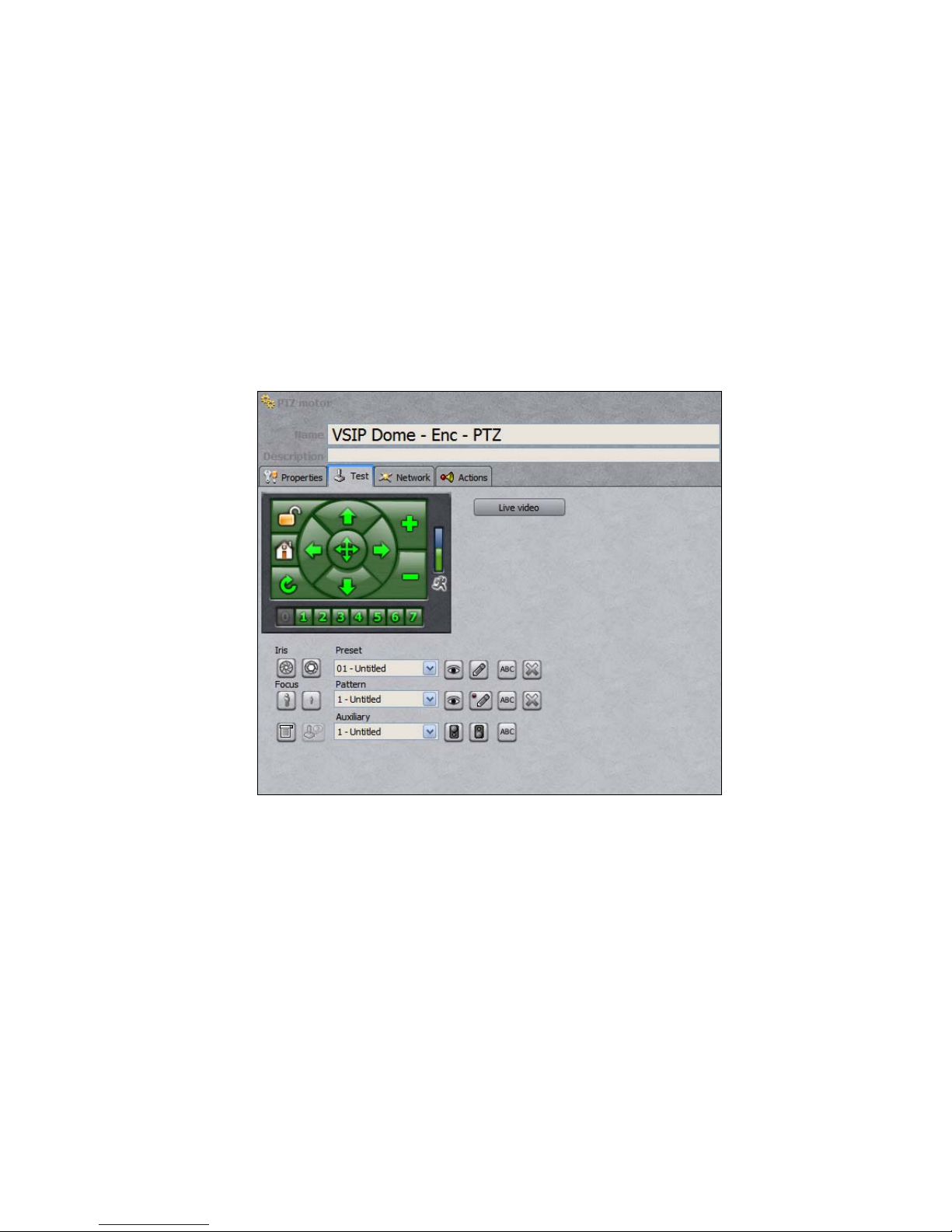
7. Switch to the
Test
tab and click the
Live video
button. Use the green on-screen
controls to test that the dome is responding to PTZ commands.
Creating Presets and Patterns
Presets and patterns can be created using the AdminCenter’s GUI interface, without having
to rely on the dome’s menu.
Figure 19 - The PTZ Configuration Pane
To create a preset:
1. Click the
Live video
button.
2. Choose the preset you would like to create from the
Preset
pull-down menu.
3. Use the on-screen controls to find the camera position/state you would like to associate
with the preset.
4. Click any of the
Iris
/
Focus
buttons if you would like to override your camera’s default
setting when using the preset.
5. Click the pencil button to save the preset and the ABC button to name it.
To create a pattern:
1. Click the
Live video
button.
2. Choose the pattern you would like to create from the
Pattern
pull-down menu.

14
3. Click the pencil button to begin recording your pattern.
4. Use the green on-screen controls and the
Iris
/
Focus
buttons to create a pattern.
5. Click the pencil button again to stop recording the pattern. You can review it by clicking
the eye button.
6. Use the
ABC
button to assign your pattern a name.
Dome Menu Setup
The dome menu can be accessed through the same PTZ Configuration Pane used to create
presets and patterns. To access the menu, click the
Live video
button and then the “menu”
button, which is located below the
Focus
buttons.
Figure 20 - Accessing the PTZ Dome’s Menu
To navigate the menu and make changes, use the green PTZ on-screen controls. Use the right
arrow button to make a selection and the left arrow button to return to the previous level of the menu. To
change setting, use the up and down arrows to toggle between options or, for numerical inputs, between digits.
The latter method is also used to enter a password, if access to the menu has been restricted.
Camera Information Setup
Sub-Menu Option Function
Current/Input
S/N
Displays the dome’s serial number, and allows users
to change it, respectively.
Camera ID Displays the camera ID.
Password Set,
Confirm/Enable
Allows users to change the menu access password.
By default, password protection is disabled and the
password is 00000000000.
Set Camera ID
Version Display’s the dome’s current firmware version.

15
Camera Settings Setup
Sub-Menu Option Function
Digital Zoom Allows users to turn the digital zoom function on or
off. By default, digital zoom is off.
Zoom Speed Allows users to change the zoom speed. The default
speed is high.
Iris Average The iris average can be set to any value between 0-
255. The default is 96. Raising the average increases
brightness.
Iris Peak The iris peak can be set to any value between 0-127.
The default is 16.
Iris Mode The iris mode can be set to M/A (default), MANU
(manual), or AUTO (automatic). The M/A setting
gives operators control of the iris when the dome is
still. At other times, the camera controls the iris.
Backlight Allows users to turn backlight compensation on or
off. The default is off.
WB Mode Allows users to change the white-balance mode. By
default, white balancing is done automatically.
WB-R Allows users to adjust the R-gain for manual white-
balance. Ranges from 0-255. The higher the R-gain,
the more reddish the image will appear.
WB-B Allows users to adjust the R-gain for manual white-
balance. Ranges from 0-255. The higher the R-gain,
the more bluish the image will appear.
Camera Setup
Focus Mode The focus mode can be set to M/A (default),
MANU (manual), or AUTO (automatic). The M/A
setting gives operators control over focus when the
dome is still. At other times, the camera has control.
Exposure Mode Setup
Sub-Menu Option Function
AE-DSS Allows users to enable or disable the dome’s Digital
Slow Shutter (DSS) capability. DSS slows the frame
rate and enhances sensitivity in low-light conditions.
The default mode is AUTO.
Shutter Allows users to manually adjust the camera’s shutter
speed. The default mode is AUTO. Available shutter
speeds vary for NTSC and PAL models.
Exposure Allows users to manually change the dome’s F-stop.
The default mode is AUTO.
Set AE Mode
B/W Mode The B/W mode is used to specify the conditions for
switching from color to black and white. The default,
16
AUTO, allows the dome to make the determination,
based on lighting. A manual mode is also available.
B/W Change Allows users to switch between COLOR and B&W
(when the B/W mode is set to MANU).
Pro-B/W This parameter is used to determine the level of light
at which the dome switches between color and black
& white mode, when set to do so automatically. At
the lowest Pro-B/W level, the camera will remain in
color mode at lower light conditions. Ranges from 1-
3. The default is 2.
Reverse Vertically reverses the screen image (off by default).
Freeze Freezes the current frame (off by default).
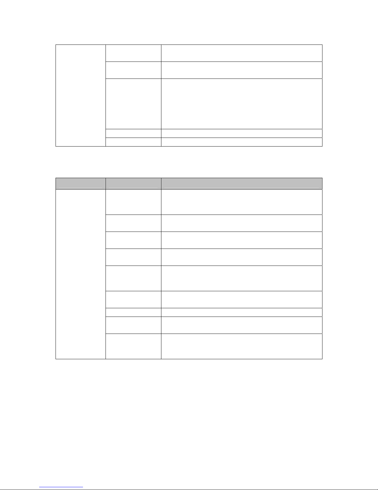
On-Screen Display Setup
Sub-Menu Option Function
Autopan Title
Display
Allows users to enable/disable the on-screen display
of autopan information (defined in the Autopan
menu). Autopan title display is turned off by default.
Preset Title
Display
Enables/disables the display of title information for
presets when they are run.
Zoom Turns on/off the display of the zoom magnification
value. Off by default.
Cursor Control Adjusts the speed of the on-screen cursor (FAST by
default).
Alarm Enable Allows the users to enable/disable the display of
alarms generated by the dome (note that these alarms
are unrelated to Latitude alarms). Off by default.
Line Lock This parameter determined whether the video’s phase
is locked to the AC phase. On by default.
Phase Adjust Allows users to manually change the video’s phase.
Clear Title Allows users to clear programmed title information
(click the right button to get into the sub-sub-menu).
OSD Setup
Privacy Mask Set This sub-sub-menu allows users to enable privacy
masks and define the masked areas. By default, all
masking options are off.
To create a privacy mask:
1. From the main menu, select
PRIVACY MASK SET
.

17
Figure 21 - Privacy Mask Setup
2. Turn
PRIVACY MASK
on.
3. If applicable, change the
MASK COLOR
(from black (
000
) to white (
015
)) and
MASK
NO.
4. Turn
MASK STATUS
on.
Figure 22 - Privacy Mask Setup
18
5. Go back to the previous menu. You should now be able to see a mask covering part of
the screen. Use the
MASK WIDTH
and
MASK CENTER
controls to change its size
and position.
To reset the mask, toggle
MASK STATUS
off and on again (to return to the menu shown
in figure 22) and select
RESET MASK
.
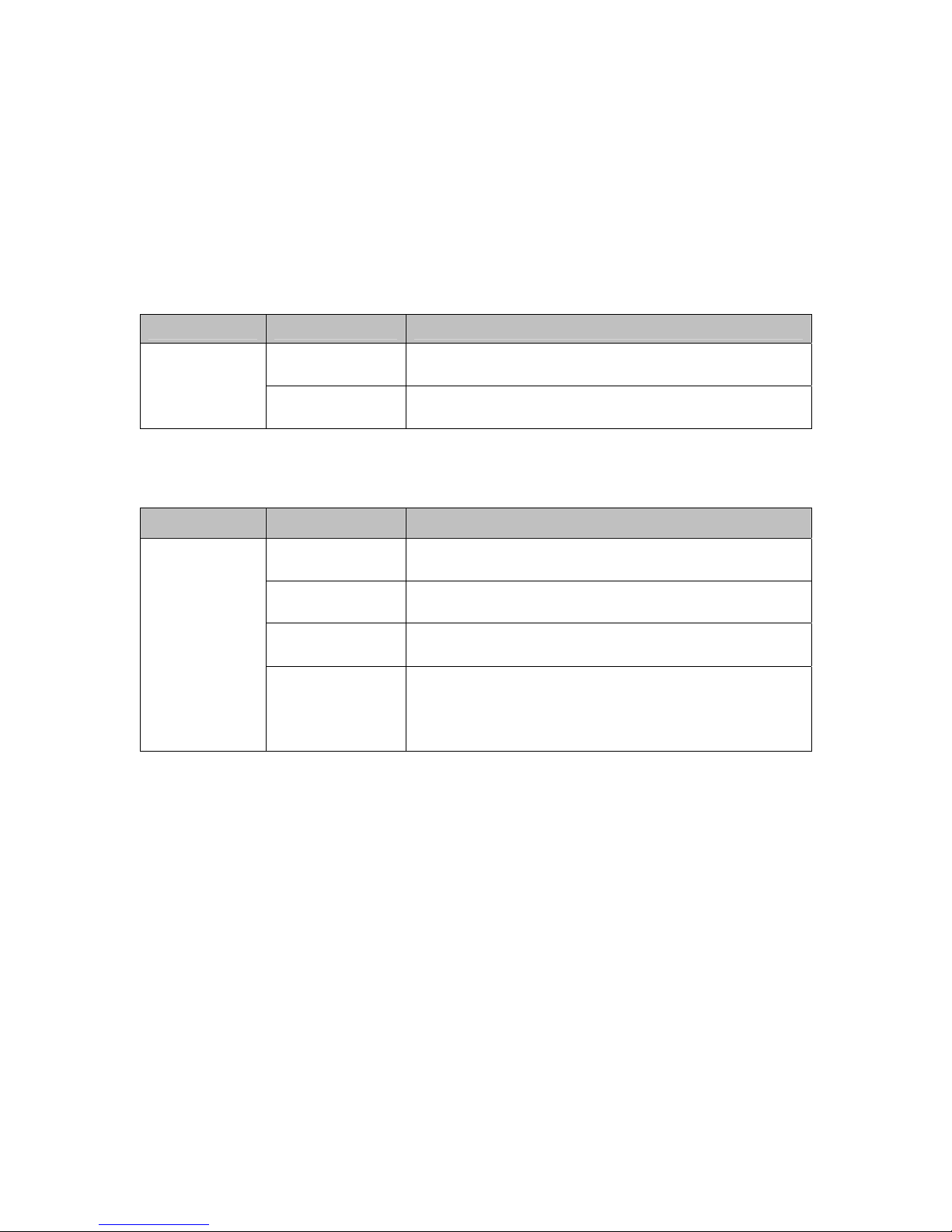
Home Position Setup
Sub-Menu Option Function
Home Position Allows users to select a preset, from 1-64, as the
dome’s home position.Config Home
Position Return Time Allows users to set the number of minutes after which
an inactive dome will return to its home position.
Autopan Setup
Sub-Menu Option Function
Direction Allows users to set the direction of movement from
the start point (Right or Left).
Speed Allows users to set the panning speed, between 0-22.
The default is 8.
Time Allows users to set the “hold” time at each boundary
position (between 0-30 seconds).
Autopan Set
Title Allows users to enter up to sixteen characters of text
to be displayed when the dome is in autopan mode.
Note that the display settings are defined in the OSD
sub-menu.
To program the start and end points:
1. Exit the dome menu and use the PTZ controls to find your desired start point.
2. Choose preset 67 from the
Preset
drop-down menu, and click the set button identified
by a pencil icon. The overlay message
68 SHOT TO END
should come up.
3. Find your desired end point.
4. Choose preset 68 from the
Preset
drop-down menu, and click the set button identified
by a pencil icon.
Once configured, autopan can be started by selecting preset 67 from the
Preset
menu and
clicking the “eye” button.

19
Area Setup
The DVTel dome allows users to define up to sixteen disjoint areas. An area’s size depends
on both the angle between its edges and the zoom level used during its configuration.
Gate 9 Gate 10
Escalator up Escalator down
Information
desk
Lounge Restaurant
Telephone
Area 1 Area 2 Area 3
Area 4
Area 5Area 6
Area 7
Area 8
Super
Dome
Figure 23 - Dividing a Dome's Field of View Into Areas
Super
Dome
Super
Dome
Area 1
Area 1
The size of Area 1 becomes
smaller when the camera zooms
in.
The size of Area 1 becomes
larger when the camera zooms
out.
Figure 24 - The Effect of Zoom Level on Area Size
To define an area:
1. From the main menu, select
AREA SET
.

20
Figure 25 - The Area Sub-Menu
2. Enter a number and a title for the area you would like to configure. To have this data
displayed as a text overlay when the camera is over the area, change
DISPLAY
to
ON
.
3. Repeat the previous step for each area you would like to set up.
4. Go to
AREA SET
and click the right arrow button.
Figure 26 - Defining an Area
5. Click the menu button and find the frame whose left edge represents the first area’s left
border. Click the green “1” button.
Table of contents

 Technical manual")


