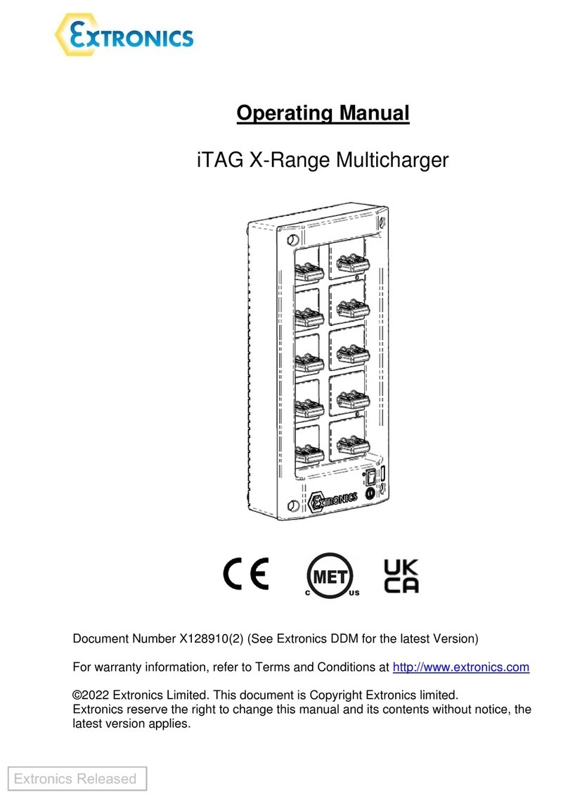
IEF Werner euroLINE 120 User manual

Translation (EN) of the original instructions (DE)
IEF-Werner GmbH | Wendelhofstraße 6 | DE-78120 Furtwangen | www.ief.de
Operating Instructions
Product name:
euroLINE 120
Product ID:
1131236


euroLINE 120
Translation (EN) of the original instructions (DE) 3 - 48
IEF-Werner GmbH | Wendelhofstraße 6 | DE-78120 Furtwangen | www.ief.de
Generated by: Reichelt Frank | MAN_EN_1131236_euroLINE120_R1d.doc
Use
■The operating instructions must be available at the component at all times.
■The operating instructions are an integral part of the component/device.
■Always use the complete original (or the original translation) of these operating instructions.
Supplier & Manufacturer
IEF-Werner GmbH
Wendelhofstraße 6
78120 Furtwangen - Germany
Phone: 07723-925-0
Telefax: 07723-925-100
www.ief.de
info@ief-werner.de
Service
Find your IEF service station on our website:
■http://www.ief.de
Legal Note
All rights, including translation, reserved. No part of the work must be reproduced in any manner
(print, copy, microfilm or other method) without the written consent of IEF-Werner GmbH or
processed, reproduced or distributed using electronic systems.
All rights reserved for the case of patent, utility sample or design patent entry reserved.
© August 2019, IEF-Werner GmbH, printed in Germany

euroLINE 120
4 - 48 Translation (EN) of the original instructions (DE)
IEF-Werner GmbH | Wendelhofstraße 6 | DE-78120 Furtwangen | www.ief.de
Generated by: Reichelt Frank | MAN_EN_1131236_euroLINE120_R1d.doc
Change History
Document Code Date Modification
MAN_EN_1131236_euroLINE120_R1a.doc October 2014 Release of this document
MAN_EN_1131236_euroLINE120_R1b.doc February 2015 Changing lubricant into Dynalub
(see section 6.2, 36).
Section “Compensation of
encoder” added
(see section 5, 27 onwards).
Section “Precautions by replacing
the carriage” added
(see section 7, 37).
MAN_EN_1131236_euroLINE120_R1c.doc November 2015 Section “Repair“ added
(see section 7.2 Replacing the
carriage 38)
MAN_EN_1131236_euroLINE120_R1d.doc August 2019 Technical data as well as parts list
and drawings changed.
Trademarks and trade names are used without any warranty of their free usability. Texts and
examples were created with great care. Nevertheless, errors cannot be excluded. IEF-Werner GmbH
does not assume legal responsibility nor any liability for missing or incorrect statements and their
consequences.
IEF-Werner GmbH reserves the right to modify or improve the software or hardware or parts of it,
as well as the supplied documentation or parts of it, without previous notice.
IEF-Werner GmbH expressly reserves all rights for replication and photomechanical reproduction,
including in extracts.
We are always grateful for suggestions for improvements and information about errors.

euroLINE 120
Translation (EN) of the original instructions (DE) 5 - 48
IEF-Werner GmbH | Wendelhofstraße 6 | DE-78120 Furtwangen | www.ief.de
Generated by: Reichelt Frank | MAN_EN_1131236_euroLINE120_R1d.doc
Table of Contents
1Declaration of Incorporation ................................................................................... 7
2Safety........................................................................................................................... 9
2.1 Definition of Warning Notes................................................................................................. 9
2.2 General Warning Notes....................................................................................................... 10
2.3 Special Hazard Warnings.................................................................................................... 11
3Intended Use ............................................................................................................ 13
3.1 Reasonably foreseeable misuse ........................................................................................ 13
4Assembly Instructions............................................................................................. 15
4.1 Installation Position.............................................................................................................. 15
4.2 Transverse Installation ........................................................................................................ 16
4.3 Attachment............................................................................................................................ 17
4.3.1 Installation of Actuators ................................................................................................ 18
4.4 Wiring ..................................................................................................................................... 19
4.4.1 Motor Cable ..................................................................................................................... 20
4.4.2 Encoder Cable ................................................................................................................. 21
4.4.3 Cable Routing .................................................................................................................. 22
4.4.4 Measuring System .......................................................................................................... 22
4.4.5 Temperature Sensor ....................................................................................................... 22
4.4.6 Installation Situation Measuring System .................................................................... 22
4.5 Technical Data ...................................................................................................................... 23
4.5.1 Tightening Torques for Screw Connection [Nm]........................................................ 23
4.5.2 Technical Data of the Linear Unit euroLINE 120 ....................................................... 23
4.5.3 Type Plate......................................................................................................................... 24
4.5.4 Load Information ............................................................................................................ 25
5Compensation of encoder...................................................................................... 27
5.1 Define angle encoder........................................................................................................... 27
5.2 Carry out homing run........................................................................................................... 31
6Maintenance............................................................................................................. 35
6.1 Maintenance of the Visual Measuring System ............................................................... 35
6.2 Lubrication of Guide Carriage ............................................................................................ 36
7Repair......................................................................................................................... 37
7.1 Precautions by replacing the carriage .............................................................................. 37
7.2 Replacing the carriage......................................................................................................... 38
8Troubleshooting ....................................................................................................... 41

euroLINE 120
6 - 48 Translation (EN) of the original instructions (DE)
IEF-Werner GmbH | Wendelhofstraße 6 | DE-78120 Furtwangen | www.ief.de
Generated by: Reichelt Frank | MAN_EN_1131236_euroLINE120_R1d.doc
9Parts Lists and Drawings ....................................................................................... 42
9.1 euroLINE 120, Parts List TG1002844................................................................................. 42
9.2 euroLINE 120, Standard Carriage, Length = 165 mm, Item No.: 1308701 ................ 44
9.3 euroLINE 120, Long Carriage, Length = 263 mm, Item No.: 1308703 ........................ 46
9.4 Drawing Accessories............................................................................................................ 48
9.4.1 Centering ring 1008664.................................................................................................. 48
9.4.2 Clamping element euroLINE 120 ................................................................................. 48

euroLINE 120
Translation (EN) of the original instructions (DE) 7 - 48
IEF-Werner GmbH | Wendelhofstraße 6 | DE-78120 Furtwangen | www.ief.de
Generated by: Reichelt Frank | MAN_EN_1131236_euroLINE120_R1d.doc
1Declaration of Incorporation
EC declaration of incorporation in the sense of the EC directive 2006/42/EC (machinery), Annex II B
The manufacturer:
IEF-Werner GmbH
Wendelhofstraße 6
78120 Furtwangen - Germany
hereby declares that the following products (the incomplete machine/partial machine):
Designation IEF-Werner parts group number
euroLINE 120 TG1002844
where possible based on the scope of delivery, corresponds to the following basic requirements of
the directive on Machinery (2006/42/EC):
Annex I, item: 1.1.2; 1.1.3; 1.1.5; 1.3.2; 1.3.4; 1.5.1; 1.7.3; 1.7.4.
The incomplete machine also corresponds to the following further directives:
■Directive 2014/30/EU of the European parliament and of the council of 26 February 2014 on the
harmonisation of the laws of the Member States relating to electromagnetic compatibility
■Directive 2014/35/EU of the European parliament and of the council of 26 February 2014 on the
harmonisation of the laws of the Member States relating to the making available on the market
of electrical equipment designed for use within certain voltage limits.
The technical documents were generated according to Annex VII part B and may be electronically
submitted to the national authorities upon justified request.
List of some applied harmonised standards:
■DIN EN ISO 12100-1,-2 / DIN EN ISO 13857 / DIN EN ISO 13850 / DIN EN 60204-1
Commissioning of the incomplete machine delivered by us is not permitted until it has been
determined that the overall system into which the incomplete machine is installed meets the basic
safety and health protection requirements according to Annex I of the above EC directive
2006/42/EC.
Name and address of the documentation officer: IEF-Werner GmbH, Furtwangen
Furtwangen, August 2019 Stefan Deck (managing director)


euroLINE 120
Translation (EN) of the original instructions (DE) 9 - 48
IEF-Werner GmbH | Wendelhofstraße 6 | DE-78120 Furtwangen | www.ief.de
Generated by: Reichelt Frank | MAN_EN_1131236_euroLINE120_R1d.doc
2Safety
2.1 Definition of Warning Notes
DANGER
Indicates danger.
Non-observance of the safety provisions causes death.
WARNING
Indicates potential danger.
Non-observance of the safety provisions may cause death or severe injury.
CAUTION
Indicates potential danger.
Non-observance of the safety provisions may cause injury.
NOTE
Indicates potential danger. Non-observance of the safety provisions may cause property damage.

euroLINE 120
10 - 48 Translation (EN) of the original instructions (DE)
IEF-Werner GmbH | Wendelhofstraße 6 | DE-78120 Furtwangen | www.ief.de
Generated by: Reichelt Frank | MAN_EN_1131236_euroLINE120_R1d.doc
2.2 General Warning Notes
The linear unit euroLINE 120 must only be commissioned by specialists who received safety-
technical instruction and are able to assess potential dangers. Furthermore, all chapters of these
operating instructions must have been read and understood completely.
WARNING
Warning of dangerous electrical voltage.
The system must be powered down for all assembly, disassembly or repair work.
Non-observance of the safety provisions may cause death.
WARNING
Linear modules must only be operated with their protective device/s.
Linear modules always have to be operated in connection with suitable safety devices
(e.g., safety cell, protective room, protective housing, light curtain).
CAUTION
Do not remove plugs or clamps when live.
Motor connectors or clamps must not be inserted or disconnected when live.
Risk of burning of the contacts and risk of flying sparks.
CAUTION
Warning of hot surface.
During operation, the heated drive may cause skin burns when touched. Install a
protective device, if possible! Do not touch the marked areas or wait for an adequate
cooling time.

euroLINE 120
Translation (EN) of the original instructions (DE) 11 - 48
IEF-Werner GmbH | Wendelhofstraße 6 | DE-78120 Furtwangen | www.ief.de
Generated by: Reichelt Frank | MAN_EN_1131236_euroLINE120_R1d.doc
2.3 Special Hazard Warnings
In addition, this operating instructions also contains the following special hazard warnings:
DANGER
Danger to persons with pacers.
There are considerable dangers for persons with pacers or other electronic implants.
Strong magnetic fields may impair implants, which may influence the pulse of wearers
of pacers in extreme cases. Persons with the above impairments must not stay close to
the linear unit euroLINE 120.
DANGER
Warning of electric shock.
The linear unit euroLINE 120 with motor and encoder connections is live. You may suffer
fatal electric shock when touching a component.
WARNING
Warning of shearing off of limbs.
These points of the components pose the danger of shearing off of limbs in operation.
WARNING
Warning of crushing of limbs.
These points of the components pose the danger of crushing of limbs in operation.
NOTE
There are strong permanent magnets in the basic body that may damage magnetic data carriers
(e.g. credit cards).
NOTE
The linear unit euroLINE 120 must not be used in the proximity of magnetic dusts and small parts!

euroLINE 120
12 - 48 Translation (EN) of the original instructions (DE)
IEF-Werner GmbH | Wendelhofstraße 6 | DE-78120 Furtwangen | www.ief.de
Generated by: Reichelt Frank | MAN_EN_1131236_euroLINE120_R1d.doc
Figure 1 Dangers at the euroLINE 120

euroLINE 120
Translation (EN) of the original instructions (DE) 13 - 48
IEF-Werner GmbH | Wendelhofstraße 6 | DE-78120 Furtwangen | www.ief.de
Generated by: Reichelt Frank | MAN_EN_1131236_euroLINE120_R1d.doc
3Intended Use
The linear unit euroLINE 120 is a precise, linear adjustment unit with an iron-applied linear motor
that is used in the commercial area as an attachment part in connection with other components.
In combination with many standardised assembly elements, as well as the other linear units of
IEF-Werner GmbH, it can be used to build complex multi-axis positioning systems as well.
Figure 2 Linear unit euroLINE 120
Areas of use of the euroLINE 120 include:
■Component insertion systems
■Handling of small parts
■Loading and unloading stations
■Measuring and test technology
■etc.
3.1 Reasonably foreseeable misuse
The linear unit euroLINE 120 is not to be used for certain applications such as the transport of
persons and animals or as a pressing/bending device for cold working of metal.
Use of the linear unit without additional measures is also not possible in special fields of
application, such as the chemical or food industry or in explosive atmospheres.
In case of doubt, consult the manufacturer.


euroLINE 120
Translation (EN) of the original instructions (DE) 15 - 48
IEF-Werner GmbH | Wendelhofstraße 6 | DE-78120 Furtwangen | www.ief.de
Generated by: Reichelt Frank | MAN_EN_1131236_euroLINE120_R1d.doc
4Assembly Instructions
4.1 Installation Position
The linear unit euroLINE 120 is only intended for horizontal use. The carriage movement must be
horizontal. Vertical use is not intended.
Figure 3 Linear unit euroLINE 120, horizontal use

euroLINE 120
16 - 48 Translation (EN) of the original instructions (DE)
IEF-Werner GmbH | Wendelhofstraße 6 | DE-78120 Furtwangen | www.ief.de
Generated by: Reichelt Frank | MAN_EN_1131236_euroLINE120_R1d.doc
4.2 Transverse Installation
For cross installation of the linear unit euroLINE 120, there are clamping elements in standard
lengths (centering ring, clamping elements).
Many axle combinations can be implemented.
Examples:
■Multiple axle carriage systems
■X/Y system
■X/Y portal system
Figure 4 X/Y system

euroLINE 120
Translation (EN) of the original instructions (DE) 17 - 48
IEF-Werner GmbH | Wendelhofstraße 6 | DE-78120 Furtwangen | www.ief.de
Generated by: Reichelt Frank | MAN_EN_1131236_euroLINE120_R1d.doc
4.3 Attachment
The euroLINE 120 can be attached to the basic body with clamping elements or to the carriage via
the 2 x 3 M5-threaded bores (see Figure 5).
Figure 5 Attachment to the basic body with the help of clamping elements
AType euroLINE 120 clamping element B M5 threaded bores, 2 x 3 pieces
(see Figure 6 and Figure 7, 18)
The installation area has to be a flat surface. Any deviations from an ideal flat plane directly affect
the processing precision.

euroLINE 120
18 - 48 Translation (EN) of the original instructions (DE)
IEF-Werner GmbH | Wendelhofstraße 6 | DE-78120 Furtwangen | www.ief.de
Generated by: Reichelt Frank | MAN_EN_1131236_euroLINE120_R1d.doc
4.3.1 Installation of Actuators
The actuators (cylinders, pick-up modules, etc.) that are to be installed on the euroLINE 120 linear
unit can be attached via the drilling pattern on the carriage.
The corresponding drilling templates are available for the two possible carriage sizes.
The position tolerance of the centering bores 7H7 is specified at ± 0.01mm.
Figure 6 euroLINE 120, standard carriage, length 165 mm
Figure 7 euroLINE 120, long carriage, length 263 mm

euroLINE 120
Translation (EN) of the original instructions (DE) 19 - 48
IEF-Werner GmbH | Wendelhofstraße 6 | DE-78120 Furtwangen | www.ief.de
Generated by: Reichelt Frank | MAN_EN_1131236_euroLINE120_R1d.doc
4.4 Wiring
There are a motor plug and an encoder plug at the terminal box:
Figure 8 Motor plug and encoder plug
AMotor plug B Encoder plug

euroLINE 120
20 - 48 Translation (EN) of the original instructions (DE)
IEF-Werner GmbH | Wendelhofstraße 6 | DE-78120 Furtwangen | www.ief.de
Generated by: Reichelt Frank | MAN_EN_1131236_euroLINE120_R1d.doc
4.4.1 Motor Cable
Figure 9 Motor cable with spring-TEC- and combicon plug
Parts list for motor cable with spring-TEC plug (item no.: 1119851).
Drawing item Article no. Designation
10 1068946 Plug-in unit, type: PC5/9-ST1-7.62
20 733086 Copper adhesive type, conductive 0.09 x 19 mm
30 726875 Wire-end sleeve, yellow, type 1.0/8 yellow
40 730076 Shrink hose, black, CGPT 12.7/6.4-0
50 1017996 Cable marker, type: KMT-07323V-9
60 730790 Motor line 5 x 1.00 mm2shielded
70 1113957 Plug 915, press-on sleeve orange 9-pin,
type: ESTA202NN00320500000
80 1113999 Contact sleeve Ø 1 mm, crimp area 0.5 – 1.5 mm²,
type : 60.251.11
Figure 10 Motor cable connections
This manual suits for next models
1
Table of contents

