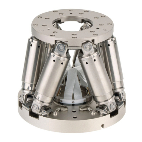
PI H-845 User manual

Physik Instrumente (PI) GmbH & Co. KG, Auf der Roemerstrasse 1, 76228 Karlsruhe, Germany
Phone +49 721 4846-0, Fax +49 721 4846-1019, Email info@pi.ws, www.pi.ws
MS222E
H
-845 Hexapod System
User Manual
Version: 2.1.1
Date: 17.09.2019
This document describes the following
product
s:
H-845.D11
Heavy-duty hexapod for 1000 kg load,
travel ranges ±110 mm (X, Y), ±50 mm (Z),
max. velocity 20 mm/s, with controller
H-845.D21
Heavy-duty hexapod for 1000 kg load,
travel ranges ±170 mm (X, Y), ±105 mm
(Z), max. velocity 20 mm/s, with controller
H-845.D31
Heavy-duty hexapod for 500 kg load, travel
ranges ±110 mm (X, Y), ±50 mm (Z), max.
velocity 40 mm/s, with controller
H-845.D41
Heavy-duty hexapod for 500 kg load, travel
ranges ±170 mm (X, Y), ±10
5 mm (Z), max.
velocity 40 mm/s, with controller
H-845.D51
Heavy-duty hexapod for 400 kg load, travel
ranges ±110 mm (X, Y), ±50 mm (Z), max.
velocity 50 mm/s, with controller
H-845.D61
Heavy-duty hexapod for 400 kg load, travel
ranges ±170 mm (X, Y), ±105 mm (Z), max.
velocity 50 mm/s, with controller

The following company names and brands are registered trademarks of Physik
Instrumente (PI) GmbH & Co. KG:
PI®, NanoCube®, PICMA®, PILine®, NEXLINE®, PiezoWalk®, NEXACT®,
Picoactuator®, PInano®, PIMag®, Q-Motion®
The patents held by PI are found in our patent list:
(http://www.physikinstrumente.com/en/about-pi/patents)
© 2019 Physik Instrumente (PI) GmbH & Co. KG, Karlsruhe, Germany. The text,
photographs, and drawings in this manual are protected by copyright. With regard
thereto, Physik Instrumente (PI) GmbH & Co. KG retains all the rights. The use of any
text, images and drawings is permitted only in part and only when indicating the
source.
Original instructions
First printing: 17.09.2019
Document number: MS222E, BRo, KSch, Version 2.1.1
Subject to change. This manual is superseded by any new release. The latest
respective release is available for download (p. 3) on our website.

1About this Document 1
1.1 Goal and Target Audience of this Manual............................................................1
1.2 Symbols and Typographic Conventions...............................................................2
1.3 Other Applicable Documents................................................................................3
1.4 Downloading Manuals ..........................................................................................3
2Safety 5
2.1 Intended Use ........................................................................................................5
2.2 General Safety Instructions..................................................................................5
2.2.1 Organizational Measures....................................................................6
2.2.2 Safety Measures during Transport.....................................................6
2.2.3 Safety Measures during Installation ...................................................6
2.2.4 Safety Measures during Start-Up.......................................................8
2.2.5 Safety Measures during Maintenance................................................9
3Product Description 11
3.1 Features and Applications..................................................................................11
3.2 Model Overview..................................................................................................12
3.3 Product View.......................................................................................................13
3.3.1 Hexapod ...........................................................................................13
3.3.2 Hexapod Controller...........................................................................14
3.3.3 Power Supply....................................................................................17
3.4 Scope of Delivery ...............................................................................................19
3.5 Technical Features.............................................................................................21
3.5.1 Struts ................................................................................................21
3.5.2 Reference Point Switch and Limit Switches.....................................21
3.5.3 Brakes...............................................................................................21
3.5.4 Control ..............................................................................................21
3.5.5 Motion...............................................................................................22
Contents

4Unpacking 27
5Installation 33
5.1 General Notes on Installation.............................................................................33
5.2 Determining the Permissible Load and Workspace ...........................................35
5.3 Attaching the Snap-on Ferrite.............................................................................36
5.4 Mounting the Hexapod on a Surface..................................................................36
5.5 Grounding the Hexapod and the Hexapod Controller........................................38
5.6 Affixing the Load to the Hexapod .......................................................................39
5.7 Optional: Removing the Coordinate Cube..........................................................40
5.8 Connecting the Hexapod System.......................................................................41
6Start-Up 43
6.1 General Notes on Start-Up.................................................................................43
6.2 Starting Up the Hexapod System.......................................................................45
6.3 Switching Off the Hexapod System....................................................................46
7Maintenance 47
7.1 Performing a Maintenance Run..........................................................................47
7.2 Packing the Hexapod for Transport....................................................................48
7.3 Replacing the Fuses of the M850B0448 Power Supply.....................................52
7.4 Cleaning the Hexapod........................................................................................54
8Troubleshooting 55
9Customer Service 57
10 Technical Data 59
10.1 Specifications......................................................................................................59
10.1.1 Data Table Hexapod.........................................................................59
10.1.2 Maximum Ratings Hexapod .............................................................61
10.1.3 Data Table Hexapod Controller........................................................61
10.1.4 Maximum Ratings Hexapod Controller.............................................62
10.1.5 Data Table M850B0448 Power Supply ............................................62
10.1.6 Maximum Ratings M850B0448 Power Supply.................................62
10.2 Ambient Conditions and Classifications .............................................................63
10.2.1 Hexapod ...........................................................................................63
10.2.2 Hexapod Controller...........................................................................63
10.2.3 M850B0448 Power Supply...............................................................64
10.3 Dimensions.........................................................................................................64
10.3.1 Hexapod ...........................................................................................65
10.3.2 Hexapod Controller...........................................................................66
10.3.3 M850B0448 Power Supply...............................................................67
10.4 Pin Assignment Hexapod...................................................................................68
10.4.1 Power Supply Connection ................................................................68
10.4.2 Data Transmission Connection ........................................................68
10.5 Pin Assignment Hexapod Controller ..................................................................69
10.5.1 I/O Connection..................................................................................69
10.5.2 Supply Power for Controller..............................................................70
11 Old Equipment Disposal 71
12 Glossary 73
13 Appendix 77
13.1 Explanations of the Performance Test Sheet.....................................................77
13.2 EU Declaration of Conformity.............................................................................78


1 About this Document
H-845 Hexapod System MS222E Version: 2.1.1 1
In this Chapter
Goal and Target Audience of this Manual..................................................................... 1
Symbols and Typographic Conventions........................................................................ 2
Other Applicable Documents......................................................................................... 3
1.1 Goal and Target Audience of this Manual
This manual contains information on the intended use of H-845 hexapod systems.
It provides information about the following items:
H845B00xx hexapod mechanics
H845B0021 hexapod controller
M850B0448 power supply
Cabling
Further information on the hexapod system can be found in the documentation listed
in “Other Applicable Documents” (p. 3).
This manual assumes that the reader has a fundamental understanding of basic servo
systems as well as motion control concepts and applicable safety procedures.
The latest versions of the user manuals are available for download (p. 3) on our
website.
1
About this Document

1 About this Document
2Version: 2.1.1 MS222E H-845 Hexapod System
1.2 Symbols and Typographic Conventions
The following symbols and typographic conventions are used in this user manual:
CAUTION
Dangerous situation
If not avoided, the dangerous situation will result in minor injury.
Actions to take to avoid the situation.
NOTICE
Dangerous situation
If not avoided, the dangerous situation will result in damage to the equipment.
Actions to take to avoid the situation.
INFORMATION
Information for easier handling, tricks, tips, etc.
Symbol Meaning
1.
2. Action consisting of several steps whose sequential
order must be observed
Action consisting of one or several steps whose
sequential order is irrelevant
List item
p. 5 Cross-reference to page 5
RS-232 Labeling of an operating element on the product
(example: socket of the RS-232 interface)
Warning sign on the product which refers to detailed
information in this manual.

1 About this Document
H-845 Hexapod System MS222E Version: 2.1.1 3
1.3 Other Applicable Documents
Device/program Document
no. Document content
C-887.5xx
controller MS247EK Short instructions for hexapod systems
MS244E User manual
C887T0007 Coordinate Systems for Hexapod Microrobots
C887T0021 Motion of the Hexapod. Position and
Orientation in Space, Center of Rotation
PI Hexapod
Simulation Tool A000T0068 Determining the workspace and the
permissible load of the hexapod
PC software
included in the
controller's scope
of delivery
Various For details, see the user manual for the C-
887.5xx controller.
1.4 Downloading Manuals
INFORMATION
If a manual is missing or problems occur with downloading:
Contact our customer service department (p. 57).
INFORMATION
For products that are supplied with software (CD in the scope of delivery), access to
the manuals is protected by a password. Protected content is only displayed on the
website after entering the access data.
You need the product CD to get the access data.
For products with CD: Get access data
1. Insert the product CD into the PC drive.
2. Switch to the Manuals directory on the CD.
3. In the Manuals directory, open the Release News (file including releasenews
in the file name).

1 About this Document
4Version: 2.1.1 MS222E H-845 Hexapod System
4. Get the access data for downloading protected content in the "User login for
software download" section of the Release News. Possible methods for
getting the access data:
−Link to a page for registering and requesting the access data
−User name and password is specified
5. If the access data needs to be requested via a registration page:
a) Follow the link in the Release News.
b) Enter the required information in the browser window.
c) Click Show login data in the browser window.
d) Note the user name and password shown in the browser window.
Downloading manuals
If you have requested access data for protected contents via a registration page (see
above):
Click the links in the browser window to change to the content for your product
and log in using the access data that you received.
General procedure:
1. Open the website www.pi.ws.
2. If access to the manuals is protected by a password:
a) Click Login.
b) Log in with the user name and password.
3. Click Search.
4. Enter the product number up to the period (e.g., C-887) into the search field.
5. Click Start search or press the Enter key.
6. Open the corresponding product detail page in the list of search results:
a) If necessary: Scroll down the list.
b) If necessary: Click Load more results at the bottom of the list.
c) Click the corresponding product in the list.
7. Click the Downloads tab.
The manuals are shown under Documentation.
8. Click the desired manual and save it to the hard disk of your PC or to a data
storage medium.

2 Safety
H-845 Hexapod System MS222E Version: 2.1.1 5
In this Chapter
Intended Use ................................................................................................................. 5
General Safety Instructions........................................................................................... 5
2.1 Intended Use
The hexapod is a laboratory device as defined by DIN EN 61010-1. It is built for indoor
use and use in an environment which is free of dirt, oil, and lubricants.
In accordance with its design, the hexapod is intended for positioning, adjusting, and
shifting of loads on six axes at various velocities.
The hexapod is part of a hexapod system. The intended use of the hexapod is only
possible in conjunction with the hexapod controller, which is part of the hexapod
system and coordinates all motion of the hexapod, and the hexapod power supply.
2.2 General Safety Instructions
The H-845 hexapod system is built according to state-of-the-art technology and
recognized safety standards. Improper use can result in personal injury and/or
damage to the hexapod system.
Only use the hexapod system for its intended purpose, and only use it if it is in
a good working order.
Read the user manuals.
Immediately eliminate any faults and malfunctions that are likely to affect
safety.
The operator is responsible for the correct installation and operation of the hexapod
system.
2
Safety

2 Safety
6Version: 2.1.1 MS222E H-845 Hexapod System
2.2.1 Organizational Measures
User manual
Always keep this user manual next to the hexapod system.
If the user manual is lost or damaged, contact our customer service
department (p. 57).
Add all information given by the manufacturer to the user manual, for example
supplements or technical notes.
If you give the hexapod system to other users, also include this user manual
as well as other relevant information provided by the manufacturer.
Only use the hexapod system on the basis of the complete user manual.
Missing information due to an incomplete user manual can result in minor
injury and damage to equipment.
Only install and operate the hexapod system after you have read and
understood this user manual.
Personnel qualification
The hexapod system may only be installed, started up, operated, maintained, and
cleaned by authorized and appropriately qualified personnel.
2.2.2 Safety Measures during Transport
There is a risk of injuries caused by crushing since the hexapod is very heavy and
capable of exerting high forces.
Keep any part of your body away from areas where they can get caught by the
hexapod.
An impermissible mechanical load can damage the hexapod.
Only send the hexapod in the original packaging.
Only transport the hexapod using a crane. The crane must lift the hexapod by
3 ring bolts and shackles affixed to the motion platform of the hexapod (p. 27).
2.2.3 Safety Measures during Installation
Depending on the tilting angle of the surface to which the hexapod is to be mounted,
the hexapod can slip, tilt or fall from the surface. There is a risk of injuries if parts of
your body get caught be the hexapod, and the hexapod can be damaged.
Position the surface where the hexapod is to be mounted horizontally.

2 Safety
H-845 Hexapod System MS222E Version: 2.1.1 7
During positioning the hexapod on a surface there is a risk of minor injuries due to the
mass of the hexapod.
When you hold the hexapod by the base plate to position it on a surface:
Ensure that your hands remain in a position where they cannot be squeezed.
If the surface where the hexapod is to be mounted cannot be positioned horizontally:
Keep any part of your body away from areas where they can get caught by the
hexapod.
Disconnect the hexapod from the crane only when the base plate of the
hexapod is securely affixed to the surface.
Impermissible mechanical load and collisions between the hexapod, the load to be
moved and the surroundings can damage the hexapod.
Only lift and align the hexapod using a crane. The crane must lift the hexapod
by 3 ring bolts and shackles affixed to the motion platform of the hexapod
(p. 27).
Do not hold the hexapod by its struts to position it on a surface.
Before installing the load, determine the limit value for the load of the hexapod
with a simulation program (p. 35).
Before installing the load, determine the workspace of the hexapod with a
simulation program (p. 35).
Make sure that the installed load observes the limit value determined with the
simulation program.
Avoid high forces and torques on the motion platform during installation of the
hexapod and the load.
When the hexapod is mounted on a tilted surface:
−Verify that the hexapod is lifted by the crane without the hexapod slipping
from the tilted surface in a sudden motion.
−Verify that the chain of the crane remains under slight tension. If the
tension is too strong, impermissible forces can be exerted on the
hexapod.
Ensure an uninterruptible power supply in order to prevent an unintentional
deactivation of the hexapod system.
Make sure that no collisions between the hexapod, the load to be moved and
the surroundings are possible in the workspace of the hexapod.
Never cover any ventilation openings as this will impede ventilation.

2 Safety
8Version: 2.1.1 MS222E H-845 Hexapod System
Incorrect mounting can warp the base plate. Warping of the base plate reduces the
accuracy.
Mount the hexapod on an even surface. The recommended evenness of the
surface is 100 µm.
The hexapod can be damaged by excessively long screws.
When selecting the screw length, observe the thickness of the motion platform
(p. 64) or the depth of the mounting holes together with the load to be
mounted.
Only use screws that do not project under the motion platform after being
screwed in.
Only mount the hexapod and a load on the mounting fixtures (holes) intended
for this purpose.
The M850B0448 power supply can be damaged due to disturbed heat dissipation.
Install the power supply only with its bottom side (equipped with rubber feet)
facing downwards.
Place the power supply in a location with adequate ventilation to prevent
internal heat build-up.
Allow at least 15 cm clearance from the front and the rear of the unit and 1 cm
from the bottom (ensured by the feet of the chassis).
2.2.4 Safety Measures during Start-Up
There is a risk of injuries caused by crushing which can occur between the moving
parts of the hexapod and a stationary part or obstacle.
Keep any part of your body away from areas where they can get caught by
moving parts.
The geometrical data used by the hexapod controller must be adapted to the hexapod.
If incorrect geometrical data is used, the hexapod can be damaged by uncontrolled
motions or collisions. The geometrical data is adapted before delivery.
Check whether the hexapod controller matches the hexapod.
A label on the rear panel of the controller indicates for which hexapod the
controller is intended.
Use the CST? command to query for the active hexapod geometry file (see
documentation of the hexapod controller). Thus you can check if the label on
the rear panel is still correct.
Only operate the hexapod with a hexapod controller whose geometrical data
is adapted to the hexapod.

2 Safety
H-845 Hexapod System MS222E Version: 2.1.1 9
Collisions can damage the hexapod, the load to be moved, and the surroundings.
Make sure that no collisions between the hexapod, the load to be moved, and
the surroundings are possible in the workspace of the hexapod.
Do not place any objects in areas where they can get caught by moving parts.
Immediately stop the motion if a malfunction occurs in the hexapod controller
(see user manual of the hexapod controller).
2.2.5 Safety Measures during Maintenance
The hexapod can become misaligned as a result of improper maintenance. The
specifications (p. 59) can change as a result.
Only loosen screws according to the instructions in this manual.


3 Product Description
H-845 Hexapod System MS222E Version: 2.1.1 11
In this Chapter
Features and Applications........................................................................................... 11
System Components................................................................................................... 12
Product View ............................................................................................................... 13
Scope of Delivery ........................................................................................................ 19
Technical Features...................................................................................................... 21
3.1 Features and Applications
The various models (p. 12) of the H-845 hexapod that are offered differ with respect to
the maximum velocity and load capacity.
The parallel-kinematic design of the hexapod offers the following advantages:
Positioning operations in six independent axes (three translational axes, three
rotational axes) with short settling times
The center of rotation moves together with the motion platform
High accuracy and step resolution in all axes
No accumulation of errors of individual axes
No friction and torques from moving cables
The hexapod is controlled with the hexapod controller, which is delivered with the
hexapod. The position commands to the hexapod controller are entered as Cartesian
coordinates.
3
Product Description

3 Product Description
12 Version: 2.1.1 MS222E H-845 Hexapod System
3.2 Model Overview
Model Designation
H-845.D11 Heavy-duty hexapod for 1000 kg load, travel ranges ±110 mm (X, Y),
±50 mm (Z), max. velocity 20 mm/s. Cable set 9 m, with 6-DOF
controller for hexapods, TCP/IP and RS-232 interface
H-845.D21 Heavy-duty hexapod for 1000 kg load, travel ranges ±170 mm (X, Y),
±105 mm (Z), max. velocity 20 mm/s. Cable set 9 m, with 6-DOF
controller for hexapods, TCP/IP and RS-232 interface
H-845.D31 Heavy-duty hexapod for 500 kg load, travel ranges ±110 mm (X, Y),
±50 mm (Z), max. velocity 40 mm/s. Cable set 9 m, with 6-DOF
controller for hexapods, TCP/IP and RS-232 interface
H-845.D41 Heavy-duty hexapod for 500 kg load, travel ranges ±170 mm (X, Y),
±105 mm (Z), max. velocity 40 mm/s. Cable set 9 m, with 6-DOF
controller for hexapods, TCP/IP and RS-232 interface
H-845.D51 Heavy-duty hexapod for 400 kg load, travel ranges ±110 mm (X, Y),
±50 mm (Z), max. velocity 50 mm/s. Cable set 9 m, with 6-DOF
controller for hexapods, TCP/IP and RS-232 interface
H-845.D61 Heavy-duty hexapod for 400 kg load, travel ranges ±170 mm (X, Y),
±105 mm (Z), max. velocity 50 mm/s. Cable set 9 m, with 6-DOF
controller for hexapods, TCP/IP and RS-232 interface

3 Product Description
H-845 Hexapod System MS222E Version: 2.1.1 13
3.3 Product View
3.3.1 Hexapod
Figure 1: Hexapod
1 Motion platform
2 Strut
3 Base plate
4 Socket for data transmission cable (Controller Out)
5 Socket for data transmission cable (Controller In)
6 Panel plug for power supply cable (24 VDC)
7 Coordinate cube
8 “Risk of crushing“ warning sign
Figure 2: Connections at hexapod base plate

3 Product Description
14 Version: 2.1.1 MS222E H-845 Hexapod System
3.3.2 Hexapod Controller
Figure 3: Front view of the hexapod controller
Element Labeling Type Function
I/O HD Sub-D 26 (f)
(p. 69) Digital inputs/outputs:
Outputs: Trigger external devices
Inputs: Use in macros
Analog inputs (multifunctional)
SPI Master Display port For future use; currently no function.
USB type A, high
insertion and
pulling force
USB interface for connecting the C-887.MC
control unit from PI
USB type A USB interface for connecting peripheral devices
RJ45 socket Network connection via TCP/IP
SPI Slave Display port For future use; currently no function.
RS-232 Sub-D 9 (m) Serial connection to PC
ERR LED
red Error indicator:
Lights up continuously: Error (error code ≠0)
Off: No error (error code = 0)
The error code can be queried with the ERR?
command. The query resets the error code to
zero and the LED is switched off.
Table of contents
Other PI Industrial Equipment manuals

PI
PI L-402 Series User manual

PI
PI L-417 9054B Series User manual

PI
PI L-412.XX9232 Series User manual

PI
PI S-340 Manual

PI
PI L-412 9025E1 Series User manual

PI
PI H-811.D2 Instruction Manual

PI
PI L-417 9232B Series User manual

PI
PI L-412.039211E0 User manual

PI
PI F-712.HA1 User manual

PI
PI L-412 9232B Series User manual