manuals.online logo
Brands
  1. Home
  2. •
  3. Brands
  4. •
  5. Eaton
  6. •
  7. Industrial Equipment
  8. •
  9. Eaton SLN018 User manual

Eaton SLN018 User manual

Instruction Booklet IB48083 Effective August 2014
Vacuum interrupter replacement
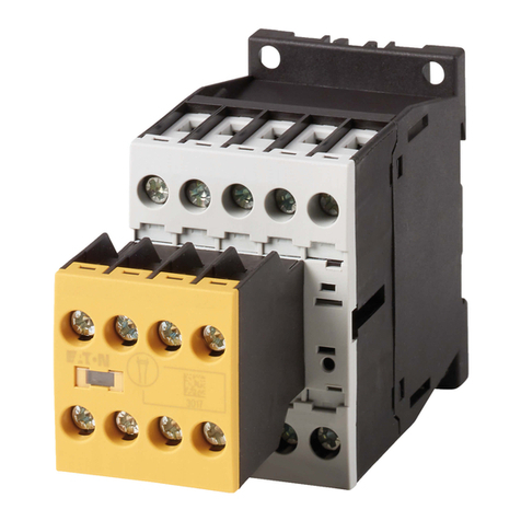
SLN018, SL12, SL15, and SJ contactors
Figure 1. Open Contactor
DANGER—HAZARDOUS VOLTAGE
READ AND UNDERSTAND THESE INSTRUCTIONS
BEFORE ATTEMPTING REPLACEMENT OF VACUUM
INTERRUPTERS. THIS EQUIPMENT SHALL BE
INSTALLED AND SERVICED ONLY BY QUALIFIED
ELECTRICAL PERSONNEL. A QUALIFIED PERSON IS ONE
WHO IS FAMILIAR WITH THE CONSTRUCTION AND
OPERATION OF THIS EQUIPMENT AND WHO IS AWARE
OF THE HAZARDS INVOLVED.
Vacuum interrupter
subassembly replacement
If it becomes necessary to replace vacuum
interrupters, proceed as follows:
1. De-energize the contactor. Remove to a
workbench.
2. Remove the top barrier assembly
(four hex-head bolts, Classic AmpgardTonly).
3. Unbolt the shunts on the line side of the
bottles. See Figure 2.
Figure 2.
Crossbar
Pivot Plate
Bottle Stud Bottle Nuts
Contact Spring
Line Terminal
Shunt
VI Bottle
VI Brace
Load Terminal
Bottle Bolt
ArmatureMagnet
Operating Coil
Control Board
Kickout Spring Lever
Adjustment Screw
Kickout Spring Lever
Kickout Springs
2
Instruction Booklet IB48083
Effective August 2014
Vacuum interrupter replacement
SLN018, SL12, SL15, and SJ contactors
EATON www.eaton.com
4. Remove control transformer primary fuses
(Classic Ampgard only).
5. Remove the hollow screw above each interrupter.
6. Remove the bottle nuts from the top stems, using a screwdriver
as shown in Figure 3. Set aside the screws, nuts, and washers.
Figure 3.
7. Remove the two 5/16-inch bolts attaching each bottle
subassembly. Set bolts aside.
8. Withdraw the interrupter subassemblies from the contactor
chassis, pulling the bottom end out first so that the top stud
clears the rear frame of the chassis. The contact springs are
loose at this point and should be captured and stored. The bottle
subassembly consists of the interrupter, shunt, and related
hardware. See Figure 1.
9. Remove the old pivot plate from the crossbar. Retain hardware.
10. Loosen and remove the bottle bolt that holds the copper conduc-
tor to the bottom of the interrupter. Retain the shim from under
the copper conductor and the copper spacer.
CAUTION
AT NO TIME DURING THE INSTALLATION OF THE NEW INTERRUPTER
SHOULD TORQUE BE APPLIED TO THE MOVING END OF THE INTERRUPTER.
INTERNAL DAMAGE MAY RESULT IF TORQUE IS APPLIED. THE USED
INTERRUPTERS SHOULD BE DESTROYED. DESTROYING THE INTERRUPTERS
WILL ENSURE THAT THEY ARE NOT LATER CONSIDERED NEW AND
INSTALLED IN ANOTHER CONTACTOR.
11. Install the new pivot plate (provided with the new interrupter kit)
on the crossbar.
12. Fasten the previously removed copper conductor to the new
interrupter with the shim between the mold frame and the
copper conductor. The bottle spacer is installed between the
interrupter and the copper conductor. Do not tighten the bolt
at this time.
13. Preset the shunt by bending the free end in a smooth curve to
touch the stud, then release.
14. Install contact springs and cups onto the top stems, with cup on
top, flange down. See Figure 4.
Figure 4.
15. Insert bottle subassemblies into chassis, putting top end in
first and guiding the bottle stud into the slot in the pivot plate.
Check to confirm that the spring and cup are between the
interrupter and the crossbar.
16. Bolt the subassembly to the chassis, using the 5/16-inch bolts,
two per pole.
1 7. Align the interrupter on the copper conductor (the bottle bolt is
loose) until the stud does not rub or touch the slot in the hole
in the pivot plate. Tighten the bottle bolt. See Figure 3. Check
alignment again to make sure it was maintained while tightening.
18. Attach shunts to the line side conductor.
19. Recheck to make sure that the bottle studs remain clear of the
pivot plate. In particular, make certain that the shunts have a
slight bow downward (from Step 12) and do not push the bottle
studs against the pivot plate. If they do touch the pivot plate,
loosen the shunts from the line side conductor and repeat
Step 12 before refastening.
20. Close the contactor by applying rated voltage from an isolated
power source, using adequate care against electrical shock.
21. Install two bottle nuts, plus the two flat washers previously
removed, onto the center pole bottle stud. Both bottle nuts must
have their threaded flanges facing UP.
3
Instruction Booklet IB48083
Effective August 2014
Vacuum interrupter replacement
SLN018, SL12, SL15, and SJ contactors
EATON www.eaton.com
22. Turn the center pole bottle nuts clockwise until they are
0.120 ± 0.005 inches from the pivot plate. This is the overtravel
gap. See Figure 5. Lock the bottle nuts with a screwdriver
inserted from the front of the frame molding, turning the screw-
driver counter-clockwise with the blade fitted from a notch in one
bottle nut across to a notch in the other bottle nut. See Figure 3.
Figure 5. Closed Contactor
23. De-energize the coil and remove the power source.
24. Note and record the length of the kickout springs. Loosen the
set screw that locks the kickout spring adjusting screw, then
loosen the kickout spring adjusting screw until the contacts of
the center pole barely touch, using a volt-ohmeter or test light
as an indicator of touch and open.
ote:N Whenever adjusting the kickout spring lever, put your free hand over
the kickout springs as a precaution.
25. With the contactor in this position and the center contacts just
touching, install and adjust the bottle nuts (and spacing washers)
on the other two poles so that these two poles make contact
simultaneously with the center pole when checked with a meter
or test light. Lock the bottle nuts as before.
26. Install the hollow screws through the guide bar onto the three
bottle studs.
27. Tighten the kickout spring adjusting screw back to the original
compressed length of the kickout springs. Check that the arma-
ture rests firmly against its stop on the molded frame. When a
screwdriver is pushed against the bottom end of the armature in
the open position, the armature must not move. If it does, the
kickout springs should be tightened further to push the armature
to a solid position. Re-tighten set-screw. Do not overtighten.
28. Install control transformer primary fuses (Classic Ampgard).
29. Install top barrier assembly (Classic Ampgard).
Overtravel Bottle Nuts
Pivot Plate
Eaton
1000 Eaton Boulevard
Cleveland, OH 44122
United States
Eaton.com
© 2014 Eaton
All Rights Reserved
Printed in USA
Publication No. IB48083 / Z15482
August 2014
Eaton is a registered trademark.
All other trademarks are property
of their respective owners.
Vacuum interrupter replacement
SLN018, SL12, SL15, and SJ contactors
Instruction Booklet IB48083
Effective August 2014

This manual suits for next models

3

Other Eaton Industrial Equipment manuals

Eaton Ulusoy URING36 - LLF User manual

Eaton

Eaton Ulusoy URING36 - LLF User manual

Eaton DX-BR Series Manual

Eaton

Eaton DX-BR Series Manual

Eaton RPR-2 User manual

Eaton

Eaton RPR-2 User manual

Eaton PKE-SWD-SP Manual

Eaton

Eaton PKE-SWD-SP Manual

Eaton easyE4 series Manual

Eaton

Eaton easyE4 series Manual

Eaton EU1E-SWD Series Manual

Eaton

Eaton EU1E-SWD Series Manual

Eaton DCF 1600TWIN Instruction Manual

Eaton

Eaton DCF 1600TWIN Instruction Manual

Eaton Airflex VC 5000 User manual

Eaton

Eaton Airflex VC 5000 User manual

Eaton Cutler-Hammer ATC-300 User manual

Eaton

Eaton Cutler-Hammer ATC-300 User manual

Eaton P3 Series Manual

Eaton

Eaton P3 Series Manual

Eaton LZMNS4-AE Series Manual

Eaton

Eaton LZMNS4-AE Series Manual

Eaton Airflex HEVC 5005 User manual

Eaton

Eaton Airflex HEVC 5005 User manual

Eaton PXR-RCAM-MRTU-I Manual

Eaton

Eaton PXR-RCAM-MRTU-I Manual

Eaton COOPER POWER SERIES User manual

Eaton

Eaton COOPER POWER SERIES User manual

Eaton Crouse-hinds series User manual

Eaton

Eaton Crouse-hinds series User manual

Eaton SOL30X2 Series Manual

Eaton

Eaton SOL30X2 Series Manual

Eaton AirFlex TLC 5004 User manual

Eaton

Eaton AirFlex TLC 5004 User manual

Eaton MSC-D-PI Series Manual

Eaton

Eaton MSC-D-PI Series Manual

Eaton Castell IZM-KLP-SO-CASTELL User manual

Eaton

Eaton Castell IZM-KLP-SO-CASTELL User manual

Eaton Power Defense Manual

Eaton

Eaton Power Defense Manual

Eaton TE series Supplement

Eaton

Eaton TE series Supplement

Eaton Magnum DS User manual

Eaton

Eaton Magnum DS User manual

Eaton NZM4-XKSFA Manual

Eaton

Eaton NZM4-XKSFA Manual

Eaton Multi-FF Series User manual

Eaton

Eaton Multi-FF Series User manual

Popular Industrial Equipment manuals by other brands

ESS 2000 Series Installation & operation manual

ESS

ESS 2000 Series Installation & operation manual

ABB Power2 340-H44 Operation manual

ABB

ABB Power2 340-H44 Operation manual

Rittal RiLine Compact SV 9635.000 Assembly and operating instructions

Rittal

Rittal RiLine Compact SV 9635.000 Assembly and operating instructions

SWR ENGINEERING ProGap operating instructions

SWR ENGINEERING

SWR ENGINEERING ProGap operating instructions

Ampeon AMP-EE01 user manual

Ampeon

Ampeon AMP-EE01 user manual

JOYCE ECBL65 manual

JOYCE

JOYCE ECBL65 manual

schmersal AZM400Z-ST-1P2P-T manual

schmersal

schmersal AZM400Z-ST-1P2P-T manual

croydon TI15-160001 D0 instruction manual

croydon

croydon TI15-160001 D0 instruction manual

CRH Leviat HALFEN HEK3 manual

CRH

CRH Leviat HALFEN HEK3 manual

Siemens 3TX7002 operating instructions

Siemens

Siemens 3TX7002 operating instructions

Dover TWG PullMaster PM50 instruction manual

Dover

Dover TWG PullMaster PM50 instruction manual

Ulvac OMT-100A instruction manual

Ulvac

Ulvac OMT-100A instruction manual

Vestil POW-CAR Series instruction manual

Vestil

Vestil POW-CAR Series instruction manual

EASTMAN E Series quick start guide

EASTMAN

EASTMAN E Series quick start guide

Danfoss AMV 310 instructions

Danfoss

Danfoss AMV 310 instructions

OK INDUSTRIAL DTM 510 manual

OK INDUSTRIAL

OK INDUSTRIAL DTM 510 manual

Duro Dyne RH MACH 70 PLATINUM EDITION owner's manual

Duro Dyne

Duro Dyne RH MACH 70 PLATINUM EDITION owner's manual

ISTpure SR240-240V instruction manual

ISTpure

ISTpure SR240-240V instruction manual

manuals.online logo
manuals.online logoBrands
  • About & Mission
  • Contact us
  • Privacy Policy
  • Terms and Conditions

Copyright 2025 Manuals.Online. All Rights Reserved.