Ier steamOvap User manual

ELECTRIC RESISTIVE STEAM HUMIDIFIER
Installation and Operation Manual
Please read and save this manual
steamOvap technologies inc, 1490 Mazuree, Montreal, Qc, H4N 1H2, Canada
Tel.: 1-844-357-4477 • www.steamOvap.com
Rev.: 210601
IER


Introduction
Foreword
Thank you for purchasing IER steamOvap electric steam Humidifier.
If you have quesons or comments please contact us:
www.steamOvap.com
1-844-357-4477
Intended use
IER electric steam humidifier is intended exclusively to produce steam from water at atmospheric
pressure for air humidificaon.
Operang condions are specified in this Installaon and Operaon Manual (IOM).
Operaon of this humidifier in the intended use scope requires that all direcons and
informaon contained in this IOM are observed.
Any other use or operaon outside the above design scope without wrien authorizaon from
steamOvap may lead to trouble and hazardous condions and will void warranty.
No alteraon or modificaon to the humidifier must be done without wrien authorizaon from
steamOvap.
Replacement of any defecve components must be done with original component and spare
parts from steamOvap representave.
Installation and Operation Manual Limitation
This IOM is intended for trained and qualified personnel and must be applied along with the
applicable local codes and regulaons.
Any work related to installaon or service for this humidifier must comply with local code and
regulaon regarding safety and prevenon of accidents.
End of life disposition
Ensure that IER electric steam humidifier is empty from water, if not proceed same way as for a
standard drain for service.
Disconnect IER electric steam humidifier from power supply, electrical control signal, water main
supply, Steam line, and drain. IER electric steam humidifier can then be removed from the wall or
stand.
IER electric steam humidifier is an electrical equipment and as such MUST not be disposed of in
domesc waste.
This humidifier should be returned to the closest steamOvap authorized representave for
proper dismantling, recycling and disposion of components according to local regulaons.

Table of content
Introduction.....................................................................................................3
Table of content..............................................................................................4
Safety warnings..............................................................................................5
Before to proceed to Installation.....................................................................6
IER Overview..................................................................................................7
Installation overview......................................................................................10
Installation – step 1 IER Positioning & Mounting...........................................12
Installation – step 2 Water supply installation................................................17
Installation – step 3 Drain installation............................................................19
Installation – step 4 Steam distribution installation........................................21
SR models for horizontal in duct humidification.......................................................21
SR models for Vertical duct - Option -V...................................................................22
SR models for round duct - Option -R.....................................................................22
SOS or SOE – steamOsorb, multi-ramp steam grid................................................24
Steam line installation..............................................................................................25
Installation – step 5 Power supply installation...............................................28
Installation – step 6 Control installation.........................................................30
Verification before start-up............................................................................32
Configuration & Operation.............................................................................33
Warranty.......................................................................................................47
Other Manuals and information that can
help you:
•Modbus tables for IER
•BACnet PICS for IER
•IER service manual
Please visit our website: steamOvap.com
for the latest revision of all manuals &
instructions
You can also visit our Youtube® channel:
youtube/steamovap and watch our 2
minutes IER service/cleaning video.
Figure 1, IER one module
Informaon contained in this manual is subject to change without noce.
To obtain the latest technical informaon visit our website at steamOvap.com
4

S A F E T Y
Safety warnings
General
Risk of electric shock.
Disconnect power supply before installaon or service.
For safety and warranty reasons, Installaon and service of this humidifier should be
carried out by trained and qualified personnel.
Any work related to installaon and service of this humidifier must comply with local code and
regulaon regarding safety and prevenon of accidents.
Electrical Warning
Risk of electric shock.
Disconnect power supply before installaon or service.
Power supply connecon must be done by a trained and qualified electrician.
Any work related to power supply installaon or service of this humidifier must comply with
local code and regulaon regarding safety and prevenon of accidents.
Water safety warning
Any work related to water supply, drain connecon as well as steam lines and condensate
returns lines installaon or service of such for this humidifier must comply with local code and
regulaon regarding safety and prevenon of accidents.
Water supply connecon must be done by a trained and qualified plumber.
Risk of malfuncon. Steam lines should not have any restricon or blockage that may
cause a burst of pressure in the steam line.
Others
Risk of flooding. In order to avoid any risk of flooding steamOvap recommends a Hi limit
humidity switch installed in the air duct downstream of the steam distribuon ramp.
Risk of freezing. Plan an an-freeze system in case of installaon in a locaon that would
be exposed to outside condions and suscepble of freezing.
Risk of malfuncon. Do not block steam outlet(s).
5

I N T E N D E D U S E
Before to proceed to Installation
Please read this Installation and Operation manual before to proceed to the Installation
Receiving & Unpacking
1. Upon receipt verify that packaging is complete and not damaged.
In case of damage, and/or missing boxes advise immediately the carrier by wring a note
on the waybill.
2. Verify that model of the humidifier matches the purchase order and that all accessories are
included.
3. Any missing item should be reported as soon as possible to steamOvap or its
representave and within 5 business days aer receipt.
steamOvap will not assume any responsibility for missing item aer this delay.
4. Proceed carefully to unpacking, and check that the humidifier and its accessories are not
damaged. in case of damage please proceed as for point 3
Included in standard delivery of IER electric steam humidifier
1. IER electric steam humidifier
2. Water supply hose
3. Collar(s) to secure steam hose on steam outlet of IER
4. 3in [80mm] long drain connecon sleeve 1-1/4in [DN32] Diam.
5. This IOM
Depending on other accessories ordered
6. Steam ramp(s)
7. Steam hose
8. Condensate hose
9. RH% sensors for duct or room, or Humidistat
10. HI Limit RH% switch, model DHL
11. Air flow switch, model DAP
IER name plate
Figure 2, IER name plate
6

O V E R V I E W
IER Overview
Model designation and options codification
Nominal Voltage
Nb of Phase
Opons
MB Mounng Bracket
FS Floor Stand
Type & Model B BACnet RS485
IER 12 - 208 / 3 - MB RT Roof top enclosure
IER electrical rating
Model Steam
Capacity
Power (kW) / Current (A)
120Vac/1p 240Vac/1p - - -
IER-02 6.3lb/h
[2.8kg/h]
2.1kW
17.5A
2.1kW
8.75A - - -
Model Steam
Capacity 208Vac/1p 240Vac/1p 208Vac/3p 380Vac/3p 480Vac/3p 600Vac/3p
IER-04 10lb/h
[4.5kg/h]
3.3kW
16.0A
3.3kW
13.9A
3.3kW
9.3A
3.3kW
4.8A
3.3kW
4.0A
3.3kW
3.2A
IER-05 15lb/h
[6.8kg/h]
5.0kW
24.0A
5.0kW
20.8A
5.0kW
13.9A
5.0kW
7.2A
5.0kW
6.0A
5.0kW
4.8A
IER-09 24lb/h
[11.4kg/h]
8.3kW
39.9A
8.3kW
34.6A
8.3kW
23.0A
8.3kW
12.0A
8.3kW
10.0A
8.3kW
8.0A
IER-12 35lb/h
[15.9kg/h] -11.5kW
47.9A
11.7kW
32.4A
11.7kW
16.8A
11.7kW
14.0A
11.7kW
11.2A
IER-17 50lb/h
[22.7kg/h] - - 16.7kW
46.3A
16.7kW
24.1A
16.7kW
20.0A
16.7kW
16.0A
IER-22 65lb/h
[29.5kg/h] - - - 21.7kW
31.3A
21.7kW
26.1A
21.7kW
20.8A
IER-24 70lb/h
[31.8kg/h] - - 23.4kW
64.8A - - -
IER-31 93lb/h
[42.3kg/h] - - - 31.0kW
44.7A
31.0kW
37.3A
31.0kW
29.8A
IER-34 100lb/h
[45.4kg/h] - - 33.4kW
92.6A - - -
IER-44 130lb/h
[59.1kg/h] - - - 43.3kW
62.5A
43.3kW
52.1A
43.3kW
41.7A
IER-62 185lb/h
[84.1kg/h] - - - 61.7kW
89.1A
61.7kW
74.2A
61.7kW
59.3A
7

O V E R V I E W
IER Dimensions & weight
DW
H
Figure 3, IER Dimensions, single module
W
Steam outlets Condensate return
Drain outlets
H
D
Water inlet
Figure 4, IER Dimensions, two modules, model IER24, 34, 44 & 62
8

O V E R V I E W
Model Steam
Capacity
Nb Cyl
+ size
Nb Steam
Outlet + Ø Dimensions Net
weightW H D
IER02 6.3lb/h
[2.8kg/h]
1x
small
1x 1-1/2in
[DN40]
20in
[510mm]
23in
[585mm]
13in
[330mm]
45lb
[21kg]
IER04 10lb/h
[4.5kg/h]
1x
small
1x 1-1/2in
[DN40]
20in
[510mm]
23in
[585mm]
13in
[330mm]
45lb
[21kg]
IER05 15lb/h
[6.8kg/h]
1x
small
1x 1-1/2in
[DN40]
20in
[510mm]
23in
[585mm]
13in
[330mm]
45lb
[21kg]
IER09 24lb/h
[11.4kg/h]
1x
small
1x 1-1/2in
[DN40]
20in
[510mm]
23in
[585mm]
13in
[330mm]
45lb
[21kg]
IER12 35lb/h
[15.9kg/h]
1x
medium
1x 2in
[DN50]
23in
[585mm]
27in
[686mm]
17in
[432mm]
68lb
[31kg]
IER17 50lb/h
[22.7kg/h]
1x
medium
1x 2in
[DN50]
23in
[585mm]
27in
[686mm]
17in
[432mm]
68lb
[31kg]
IER22 65lb/h
[29.5kg/h]
1x
medium
1x 2in
[DN50]
23in
[585mm]
27in
[686mm]
17in
[432mm]
68lb
[31kg]
IER24 70lb/h
[31.8kg/h]
2x
medium
2x 2in
[DN50]
42in
[1067mm]
27in
[686mm]
17in
[432mm]
136lb
[62kg]
IER31 93lb/h
[42.3kg/h]
1x
medium
1x 21/2in
[DN65]
23in
[585mm]
27in
[686mm]
17in
[432mm]
68lb
[31kg]
IER34 100lb/h
[45.4kg/h]
2x
medium
2x 2in
[DN50]
42in
[1067mm]
27in
[686mm]
17in
[432mm]
136lb
[62kg]
IER44 130lb/h
[59.1kg/h]
2x
medium
2x 2in
[DN50]
42in
[1067mm]
27in
[686mm]
17in
[432mm]
136lb
[62kg]
IER62 185lb/h
[84.1kg/h]
2x
medium
2x 2-1/2in
[DN65]
42in
[1067mm]
27in
[686mm]
17in
[432mm]
136lb
[62kg]
9
I N S T A L L A T I O N
Installation overview
General
1. Installaon of this humidifier should be carried out by trained and qualified personnel.
2. Any work related to installaon of this humidifier must comply with local code and
regulaon regarding safety and prevenon of accidents.
WARNING. Risk of electric shock.
Power supply must be disconnected during installaon.
Main power should be connected only aer all installaon steps have been completed
and properly verified.
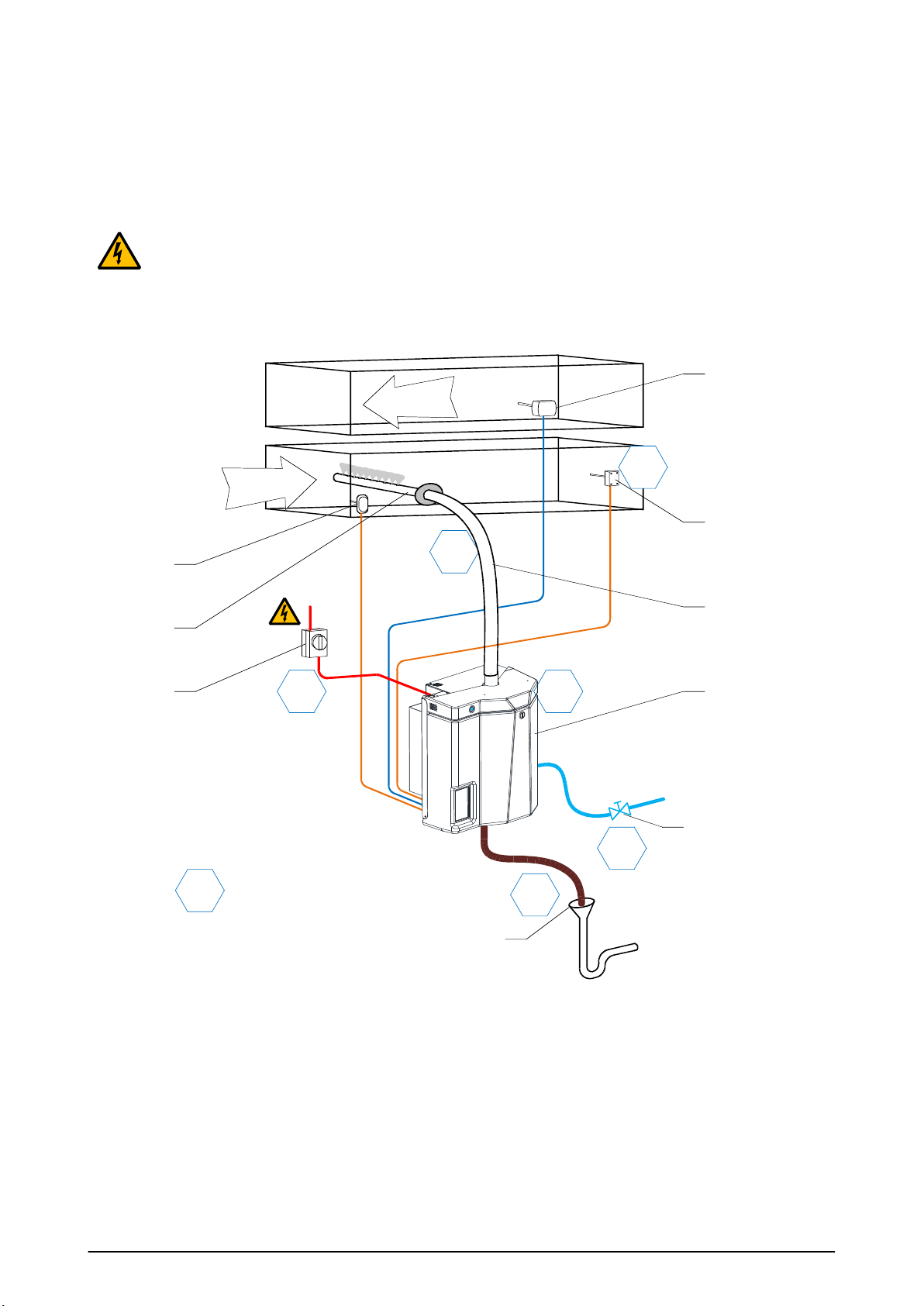
Typical installation with steam ramp
Figure 5, installaon overview with steam distribuon in duct
10
Air
Air
SUPPLY
RETURN
RH% Sensor
HI-Limit RH%
Safety switch
IER
Electric Steam
Humidifier
Open & deported Drain
with P Trap
Air flow
Safety switch
Line Voltage
Disconnect
switch
Shut-off valve on water
supply line
Steam ramp
Steam line
(hose)
1
2
3
4
5
6
0
Installaon steps

I N S T A L L A T I O N
Installation steps:
1. Posioning & mounng of IER electric steam humidifier
2. Water supply installaon
3. Drain installaon
4. Steam line installaon for duct humidificaon
or Direct humidificaon in room
5. Power supply installaon
6. Safety & RH% control installaon
Typical installation with SB- space blower
IER
Electric Steam
Humidifier
SB
Space blower
Condensate
return hose
Shut-off valve on
water supply line
Open & deported
Drain with P Trap
Room RH% sensor
Line voltage
disconnect switch
Steam hose
1
2
3
4
5
6
Figure 6, IER with remote Space blower typical installaon
Typical installation steps:
1. Posioning & mounng of IER electric steam humidifier
Space blower installaon (only if remote)
2. Steam & condensate return hose or piping
3. Water supply installaon
4. Drain installaon
5. Power supply installaon
6. RH% control installaon
11

I N S T A L L A T I O N
Installation – step 1
IER Positioning & Mounting
General guidelines for positioning
IER electric steam humidifier should be posioned so that:
Length of the steam line (or hose) is as short as possible,
In case steam hose is used, the bend radius of 12in (300mm) is ensured
Humidifier is easily accessible for service
CAUTION. Risk of malfuncon due to vibraon. Do Not mount IER electric steam
humidifier directly on venlaon duct.
CAUTION. Risk of flooding. Ensure that the local where IER electric steam humidifier will
be installed is equipped with floor drain.
In case of no floor drain is available; installaon of a water leak detector is required in
order to prevent any flooding in case of abnormal operaon or service.
IER steam humidifier should be installed in a well-venlated and dry environment.
If local is subject to below freezing point temperature, acvaon of ant freezing funcon of the
IER steam humidifier is required.
For outdoor installaon please contact your steamOvap representave to order and install special
RT outdoor enclosure for IER.
IER maximum ambient condions:
Temperature: 41°F to 113°F [+5 to +45°C]
Relave Humidity: 90%RH max (non condensing)
Ingress Protecon for IER standard enclosure: IP30
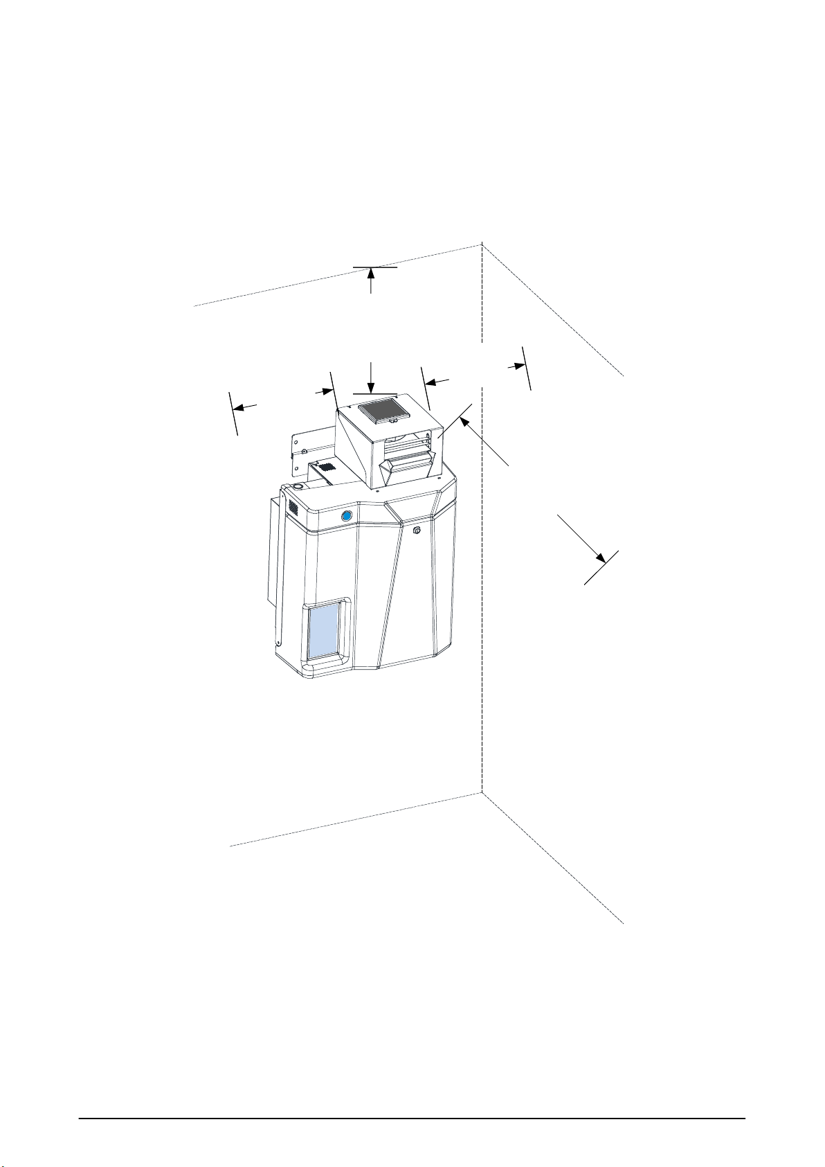
Clearances
5in min.
0in min.
12in standard
6in min.
24in standard
12in min.
30in min.
Figure 7, minimum clearances
12
I N S T A L L A T I O N
Clearance guidelines
There is no minimum clearance on both side of the IER humidifier, however it is a good pracce to
allow a clearance of 4 to 8 in [100 to 200mm] for ease of installaon and service
Allow a minimum clearance of 24in [610mm] with floor to allow for proper drain slope and drain
pipe column.
Front clearance of 30in [762mm] is required for access to the IER humidifier.
Top clearance is required of 12in [304mm] for access and ease of steam line connecon.
Clearances for IER with space blower
Min. 24in
[60cm]
Min. 80in
[200cm]
Min. 0in
[0cm]Min. 0in
[0cm]
Figure 8, minimum clearances for SB
Clearance guidelines
There is no minimum clearance on both side of the SB- space blower, but it is a good pracce to
have a clearance of 4 to 8 in [100 to 200mm] for ease of installaon and service.
Front clearance of 80in [2000mm] is required for steam absorpon.
A 24in [600mm] top clearance above SB – space blower is required for access and for steam
absorpon to avoid any condensing on the ceiling.
13

I N S T A L L A T I O N
Mounting holes positions & weights
M1
M2
M3
M4
Mounng holes paern
Electrical panel
M5
Figure 9, mounng holes single module
(IER 04 to 31)
M1
M2
Mounng holes paern
M3
M4
Electrical panel
M6
M5
Figure 10, mounng holes double module
(IER24, 34, 44 & 62)
Model Mounng holes posions (in) [mm]
M1 M2 M3 M4 M5 M6
IER02 to 09 2
[51]
8
[203]
½
[13]
19.25
[489]
6
[152] -
IER12 to 31 2
[51]
11.25
[286]
½
[13]
23.5
[597]
7.8
[197] -
IER24, 34,
44 & 62
2
[51]
34.3
[871]
½
[13]
23.5
[597]
7.8
[197]
30.7
[782]
Weight
Model Nb Cyl + size Net Weight Oper. Weight
IER02 1x small
45lb
[21kg]
74lb
[34kg]
IER04 1x small
IER05 1x small
IER09 1x small
IER12 1x medium
68lb
[31kg]
118lb
[54kg]
IER17 1x medium
IER22 1x medium
IER31 1x medium
IER24 2x medium
136lb
[62kg]
236lb
[107kg]
IER34 2x medium
IER44 2x medium
IER62 2x medium
14

I N S T A L L A T I O N
General guidelines for Mounting
CAUTION. Risk of malfuncon. IER electric steam humidifier must be levelled
in X & Z axis.
Installaon on wall (without mounng bracket)
1. Verify that wall structure and strength is appropriate to support the operang weight of
the IER electric steam humidifier.
In case, the wall is not solid enough to support operang weight of IER electric steam
humidifier, install humidifier on the floor stand (FS opon is available to your steamOvap
representave).
2. Mark the wall or support according to the above holes locaon, and drill 4 holes to the wall
or support as per the size of anchors and/or screws.
3. Use anchors of sufficient size (at least 1/4in [6mm]). Insert those anchors and the 2 top
screws, ensure that the screw heads extends 1/4in [6mm] from the wall, so that the IER
electric steam humidifier will be able to be hung on those 2 screws.
4. With front cover removed, hung the IER electric steam humidifier onto the 2 top screws.
Insert the boom screw through the back plate of the humidifier and into the anchors in
the wall.
Ensure that the humidifier is properly levelled.
Tighten the 3 screws. Re verify the level in the 2 direcon X and Z axis.
5. Re-install the front cover to the humidifier.
6. Oponal Mounng bracket (opon MB) is available to your steamOvap representave in
order to ease up wall mounng process.
15

I N S T A L L A T I O N
Installaon on wall (with mounng bracket – opon MB)
1. Oponal Mounng bracket (opon MB) is available to your steamOvap representave in
order to ease up wall mounng process.
2. Verify that wall structure and strength is appropriate to support the operang weight of
the IER electric steam humidifier.
In case, the wall is not solid enough to support operang weight of IER electric steam
humidifier, install it on a floor stand (FS opon is available to your steamOvap
representave).
3. Mark the wall or support according to the mounng bracket holes locaon, Drill holes to
the wall or support to aach the bracket to the wall as per the size of anchors and/or
screws.
Distance between the 2 holes in mounng bracket is 15in [381mm]
15in
[381mm]
Figure 11, Installaon with Mounng bracket
4. Use anchors of sufficient size (at least 1/4in [6mm]). Install the mounng bracket to the
wall or support.
Ensure that the mounng bracket is properly levelled.
5. With front cover removed, hung the IER electric steam humidifier onto the mounng
bracket.
6. Install the 2 supplied screws to avoid the IER humidifier to move up from the mounng
bracket.
7. Re-install the front cover to the humidifier.
Installaon on Floor Stand (opon FS)
1. Ensure that the floor structure and strength is appropriate to support the operang weight
of the IER electric steam humidifier.
2. Aach the floor stand to the floor or structure to avoid any movement of the IER electric
steam humidifier.
You can use bolt or screws to aach this one to surrounding structure or to the floor.
3. Install Humidifier (with front cover removed) on the floor stand and secure it with supplied
bolts.
4. Re-install the front cover to the humidifier.
16

I N S T A L L A T I O N
Installation – step 2
Water supply installation
Water supply specification & quality:
Water supply pressure: 15 to 80PSI [1 to 5bar]
Water supply temperature: 37 to 105°F [3 to 40°C]
IER electric steam humidifier can accept a wide range of water quality.
Untreated water will lead to scale deposits that will need to be regularly removed from steam
chamber.
Use of addives such as scale inhibitor or corrosion inhibitors, disinfectants or other can impair
the normal operaon of the humidifier and are not allowed.
Water supply conducvity: 1 to 1500µS/cm
Water supply hardness: 0 to 16grains/gallon [0 to 15°gH][268mg CaCO3/l]
Water supply PH: 6.5 to 7.5
Water supply chloride content: 0 to 50ppm
Flexible braided hose supplied
Connecon G3/4’’
Drain
Water supply
Filter (10 µ) – recommanded [by others]
( if connected to tap water main)
Manual shut off valve
[by others]
Connecon 3/8’’
10.2in [259mm]
1-1/8in
[28.5mm]
Figure 12, water supply connecon
17

I N S T A L L A T I O N
Figure 13, water supply connecon, model IER24, 34, 44 & 62
Water supply connection:
1. Install a manual shut off valve (supplied by others) on the water main line.
2. If IER humidifier is supplied with tap water it is recommended to install a 10µ sediment
filter (supplied by others) on the line.
Alternavely steamOvap can provide a 2 stages pre-filter 5 + 1μ PP filter as extra
protecon and filtraon (model WF-51).
3. A flexible braided hose is supplied for an easy and secure connecon to the humidifier
water supply inlet.
This flexible braided hose will ease of the installaon and act as shock absorber and
protecon for the internal water fill valve.
18
Flexible hose (by others)
NPT ½ in female
Water supply
Filter (10 µ) – recommanded [by others]
( if connected to tap water main)
Manual shut off valve
[by others]
Connecon 3/8’’
10.2in [259mm]
1-1/8in
[28.5mm]
Drain
Drain

I N S T A L L A T I O N
Installation – step 3
Drain installation
Water drained specification:
Drained water maximum temperature: 140°F [60°C] (when supplied with cold water supply)
Drained water flow rate: 6.6 GPM [25 l/min]
Drain outlet dimension: IER04 to IER31: (1x)1-1/4in [32mm]
IER24. IER34, IER44 & IER62: (2x)1-1/4in [32mm]
Drain volume for full cylinder drain: IER04 to 09: 5.5Gal [21L]
IER12, IER17, IER22, IER31: 12Gal [46L]
IER24, 34, 44 & 62: 24Gal [86.5L]
IER humidifier
Drain
Connecon sleeve 1-1/4in [32mm]
(by others)
Slope minimum 5°
P trap
Open drain offset from IER
1-1/2in [40mm] minimum
2 collars
(by others)
18in [45cm]
minimum
18in [45cm]
minimum
Figure 14, water drain connecon (single module)
Connecon sleeve 1-1/4in [32mm]
(supplied)
2 collars
(by others)
IER module 2
Drain
Slope minimum 5°
P trap
Open drain offset from IER
1-1/2in [40mm] minimum
18in [45cm]
minimum
18in [45cm]
minimum
IER module 1
Figure 15, water drain connecon, 2 modules, model IER24, 34, 44 & 62
19

I N S T A L L A T I O N
Risk of overflow.
✔A minimum slope angle of 5 degree of the drain hose or pipe and a minimum length of
24in [60cm] must be provided between IER’s module drain outlet and building’s open
drain inlet.
✔Do not reduce diameter of the drain line. Drain line between IER’s module drain outlet and
building’s open drain inlet must be 1-1/4in [DN32] diameter minimum
✔18in [45cm] minimum vercal run before P trap or obstrucon must be provided.
✔Do not install P-trap directly (or any other obstrucon) at the IER’s drain outlet.
Installation steps:
Important note: There is one drain outlet per IER module.
So there are 2 drain outlets for models IER24, IER34, IER44 and IER62.
1. Ensure that an Open drain with a P-trap is installed offset from the IER humidifier.
Main building drain diameter should be
◦1-1/2in [DN40] for single module IER
◦2in [DN50] for two modules IER (model IER24, IER34, IER44 or IER62)
in case such drain diameter is not available (i.e. in old building), increase the diameter or
height of vercal run before to enter the main building drain.
Refer to informaon of full cylinder volume above for volume calculaon.
2. Drain line can be made either with flexible hose or hard pipe.
Supplied connecon sleeve 1-1/4 [32mm] allow for ease of connecon to IER’s module
drain outlet to the drain pipe, and secure it with the supplied 2 collars.
✔Drain line must be slopped - 5° minimum slope from IER module to building’s open
drain inlet.
✔Do not reduce 1-1/4in [DN32] diameter at any point of the drain line
✔Avoid short 90° elbow
✔a minimum 18in [45cm] vercal run pipe must be provided upstream any P-trap or any
other obstrucon.
20
Table of contents
Popular Humidifier manuals by other brands


Vicks
Vicks VH5000E User instructions

Aprilaire
Aprilaire 400 Series Instructions and installation instructions

Brune
Brune B 125 Instructions for use

Hamilton Beach
Hamilton Beach 840074800 user guide

Helios
Helios HygroBox KWL HB 250 EH L Installation and operating instructions

CLAIRION
CLAIRION SA-1015 instruction manual

DriSteem
DriSteem HUMIDI-TECH Installation, operation and maintenance manual

Holmes
Holmes HM7306 owner's manual

MoistAir
MoistAir MA0600 Use and care guide

Stadler Form
Stadler Form Jack operating instructions

DriSteem
DriSteem GTS SERIES Installation, operation and maintenance manual

Bort
Bort BLF-210 user manual