Ier Automatic Systems PNG3 Series User manual

PNG3XX OPTICAL PORTAL
PNG3XX INSTALLATION MANUAL
NAM-PNG3xx-TM-EN-C.doc
The information contained in this document is the
p
roperty of Automatic
Systems and is confidential. The recipient shall refrain from using it for any
p
urpose other than the use of the products or the execution of the project to
which it refers and from communicating it to third parties without written prior
agreement of Automatic Systems. Document subject to change without notice.
Optical Portal
“PNG38X-39X Series”
INSTALLATION MANUAL

PNG3XX INSTALLATION MANUAL
NAM-PNG3xx-TM-EN-C.doc
The information contained in this document is the property of Automatic
Systems and is confidential. The recipient shall refrain from using it for any
p
urpose other than the use of the products or the execution of the project to
which it refers and from communicating it to third parties without written prior
agreement of Automatic Systems. Document subject to change without notice.
2
Table of contents
1. IMPORTANT INFORMATION ..........................................................................................................................................6
1.1 Direction Names and Conventions.....................................................................................................7
1.2 Before You Begin – Required Objects................................................................................................7
1.3 Required Cables or Conduits.............................................................................................................8
1.4 U.L. (Underwriters Laboratories) Notes..............................................................................................9
1.5 Installation Notes – Measurements..................................................................................................10
1.6 Baseplates......................................................................................................................................11
1.7 Emergency Opening........................................................................................................................13
2. INSTALLATION..............................................................................................................................................................14
2.1 Move and Unpack Equipment ..........................................................................................................14
2.2 Equipment Zones (locations) and Conventions.................................................................................15
2.2.1 Conventions and Locations .......................................................................................................15
2.2.2 Location MF (Master Front): ......................................................................................................16
2.2.3 Location MR (Master Rear): ......................................................................................................17
2.2.4 Location SR (Slave-Rear):.........................................................................................................18
2.3 Preliminary Site Work......................................................................................................................19
2.4 Installing the Unit............................................................................................................................22
2.5 Electrical Connections.....................................................................................................................25
2.5.1 Power Requirements.................................................................................................................25
2.6 Installation Wiring ...........................................................................................................................26
2.6.1 Master (Right) Unit....................................................................................................................26
2.6.2 Intermediate Unit – Master Side ................................................................................................26
2.6.3 Intermediate Unit – Slave Side ..................................................................................................27
2.6.4 Slave (Left) Unit........................................................................................................................27
2.7 AS1007 Board (Interface)................................................................................................................28
2.8 Wiring Principle for One Lane:.........................................................................................................30
2.9 Wiring Principle for Multiple Lanes: .................................................................................................31
2.10 OPTIONS - Remote Control Panel (Remote Console).....................................................................32
3. START-UP......................................................................................................................................................................34
3.1 Final Adjustments ...........................................................................................................................34
3.1.1 Detailed Calibration Method of Omron Type Photocells.............................................................. 34
3.1.2 Detailed Limit Switches Adjustment Procedure. .........................................................................37
3.2 Check List.......................................................................................................................................40
3.3 Troubleshooting ..............................................................................................................................40

PNG3XX INSTALLATION MANUAL
NAM-PNG3xx-TM-EN-C.doc
The information contained in this document is the property of Automatic
Systems and is confidential. The recipient shall refrain from using it for any
p
urpose other than the use of the products or the execution of the project to
which it refers and from communicating it to third parties without written prior
agreement of Automatic Systems. Document subject to change without notice.
3
4. REFERENCE..................................................................................................................................................................41
4.1 Low Voltage Cables ........................................................................................................................41
4.1.1 Belden 8466 .............................................................................................................................41
4.2 Motor Interconnect Cable ................................................................................................................43
4.1.1 Belden 29500............................................................................................................................43
4.2 Belden Remote Console Cable........................................................................................................46
4.3.1 Belden 8459 .............................................................................................................................46
4.3.2 Belden 540BUE.........................................................................................................................47
4.3.3 Belden 530BUE.........................................................................................................................48
4.4 Electrical Diagram...........................................................................................................................49
4.4.1 Interconnect Diagram................................................................................................................49
4.4.2 Wiring Diagram.........................................................................................................................50

PNG3XX INSTALLATION MANUAL
NAM-PNG3xx-TM-EN-C.doc
The information contained in this document is the property of Automatic
Systems and is confidential. The recipient shall refrain from using it for any
p
urpose other than the use of the products or the execution of the project to
which it refers and from communicating it to third parties without written prior
agreement of Automatic Systems. Document subject to change without notice.
4
Illustrations
Figure 1: Baseplate Important Areas.................................................................................................................................7
Figure 2: 380 Baseplate...................................................................................................................................................11
Figure 3: 390 Baseplate...................................................................................................................................................11
Figure 4: 381 Baseplate...................................................................................................................................................12
Figure 5: 391 Baseplate...................................................................................................................................................12
Figure 6: 382 Baseplate...................................................................................................................................................12
Figure 7: 392 Baseplate...................................................................................................................................................13
Figure 8: Emergency Opening: Power Shut Down Wiring ..............................................................................................13
Figure 9: Hoods and Doors..............................................................................................................................................14
Figure 10: - Areas & Component Location......................................................................................................................15
Figure 11: - Power Supply Backplate ..............................................................................................................................16
Figure 12: PLC Backplate and Main Power Supply Junction Box..................................................................................17
Figure 13: –Slave Unit Low Voltage & Motor Interconnection.........................................................................................18
Figure 14 – PNG LAYOUT ..............................................................................................................................................19
Figure 15 - Anchoring Bracket.........................................................................................................................................20
Figure 16 - Right Baseplate (Master) Representation with Punched Holes and Anchors...............................................21
Figure 17 - Baseplate Installation with Anchors Set and Conduit Cutout........................................................................22
Figure 18: Measuring Finger Shutter Openings ..............................................................................................................23
Figure 19 Leveling the PNG ...........................................................................................................................................24
Figure 20: AS1007 Interface Board Connection Points...................................................................................................28
Figure 21: X13 Terminals ................................................................................................................................................29
Figure 22: X14 Terminals ................................................................................................................................................29
Figure 23: Wiring Principle for Single Lane.....................................................................................................................30
Figure 24: Wiring Principle for Multiple Lanes................................................................................................................31
Figure 25: Master-Slave Control Panels..........................................................................................................................32
Figure 26: Rack Mount Single Control Panel ..................................................................................................................33
Figure 27: Control Panel with Backbox ...........................................................................................................................33
Figure 28: Cell Numbers..................................................................................................................................................34
Figure 29 : Closing Limit Switch Adjustment Step 1-3.....................................................................................................37
Figure 30 : Closing Limit Switch Adjustment Step 4-7.....................................................................................................38
Figure 31 : Closing Limit Switch Adjustment Step 8-10...................................................................................................38
Figure 32 : Opening Limit Switch Adjustment Step 1-4...................................................................................................39
Figure 33 : PNG-EL-01-EN-D Interconnect Wiring Diagram...........................................................................................49
Figure 34: 082703-E18-EN-F Power Supply – Drive Wiring Diagram.............................................................................50

PNG3XX INSTALLATION MANUAL
NAM-PNG3xx-TM-EN-C.doc
The information contained in this document is the property of Automatic
Systems and is confidential. The recipient shall refrain from using it for any
p
urpose other than the use of the products or the execution of the project to
which it refers and from communicating it to third parties without written prior
agreement of Automatic Systems. Document subject to change without notice.
5
Thank you for buying an Automatic Systems PNG.
WARNING
YOUR OPTICAL PORTAL "PNG38X-39X"IS MADE VARIOUS MECHANICAL AND
ELECTRICAL COMPONENTS.CARELESSNESS DURING ANY WORK ON THE MACHINE MAY
SERIOUSLY ENDANGER YOUR SAFETY.AS SOON AS YOU OPEN THE HOUSING,SWITCH
OFF THE MAIN CIRCUIT BREAKER IN THE MASTER UNIT,WHICH IS LOCATED BEHIND THE
FRONT SIDE DOOR (MF). BE CAREFUL WHEN HANDLING ANY INTERNAL COMPONENT
WHICH MIGHT BE POWERED OR COULD BE SET IN MOTION.WHEN WORKING ON
CIRCUITS,IT IS RECOMMENDED:
DO NOT DISCONNECT WIRES WITHOUT FIRST MARKING THEIR TERMINALS;
DO NOT REMOVE ANY CONNECTOR WITHOUT FIRST MARKING ITS EXACT POSITION

PNG3XX INSTALLATION MANUAL
NAM-PNG3xx-TM-EN-C.doc
The information contained in this document is the property of Automatic
Systems and is confidential. The recipient shall refrain from using it for any
p
urpose other than the use of the products or the execution of the project to
which it refers and from communicating it to third parties without written prior
agreement of Automatic Systems. Document subject to change without notice.
6
1. IMPORTANT INFORMATION
IMPORTANT: SAFETY INSTRUCTIONS
WARNING – TO REDUCE THE RISK OF INJURY OR DEATH, READ
AND FOLLOW ALL SAFETY INSTRUCTIONS BEFORE INSTALLING,
OPERATING, OR SERVICING THE PNG.
Installing an access control obstacle entails
responsibilities with regard to the safety of people:
For users
•The obstacles must be completely visible to the user as well as to any operators before being
actuated.
•Forbidding access to unaccompanied children is highly recommended.
In the basic configuration (without the optional detection cell), detection only starts at a certain height.
Therefore, children could place their hands on the obstacle without being detected and risk being hurt
if the obstacle opens for an authorized passage while their hands are there.
•The utmost care must also be taken with pets, which must be kept on leash and under the control of
their owners.
For technical staff
•All operations performed on the equipment must be undertaken by qualified personnel. All operations
that are not authorized or carried out on this product by an unqualified technician shall automatically
and ipso jure lead to the denial of the manufacturer’s warranty.
•KEEP PNG PROPERLY MAINTAINED. When servicing, keep the place around the PNG secured to avoid risk
of injuries if the optical PNG were to be activated without warning.
•The access keys to the mechanism must only be used by personnel informed of the electrical and
mechanical risks incurred by negligent handling. This person is required to lock the mechanism’s
access panel after finishing the work.
•For all operations that do not require the motor or the programmable control logic unit to be on, turn
off the power supply using the PNG main circuit breaker.
•All internal elements that could be powered or move must be handled with care.
•The equipment is configured in “minimal risk” mode for its users. All modifications of the parameters
must be undertaken by experienced and qualified personnel and in no way entail the responsibility of
Automatic Systems.

PNG3XX INSTALLATION MANUAL
NAM-PNG3xx-TM-EN-C.doc
The information contained in this document is the property of Automatic
Systems and is confidential. The recipient shall refrain from using it for any
p
urpose other than the use of the products or the execution of the project to
which it refers and from communicating it to third parties without written prior
agreement of Automatic Systems. Document subject to change without notice.
7
1.1 Direction Names and Conventions
•Direction A: is the direction a pedestrian is traveling as one enters the premises from uncontrolled
to secure areas
•Direction B: is the direction a pedestrian travels when exiting the secure space to leave the
premises.
•AMaster unit is on the right side of a lane when traveling in direction A.
•A Slave unit is on the left side of the lane when traveling from direction A
•Intermediate units contain both master and slave in a single housing. It is a master for one side
(left corridor) and slave for the other (right corridor) when traveling in direction A.
•Crossing Request is the same as R.T.E (request to enter/exit) or “open to allow 1 person”.
1.2 Before You Begin – Required Objects
In order to successfully complete the optical portal installation it is essential that you have a proper plan in
place on how to proceed. Before you can actually install any PNG unit, you must first have properly and
legibly marked the area and exact position where the PNG are to be installed. You should also have
already run your electric and control conduits and have the baseplates positioned on the floor, with the
anchor bolts set through the baseplate into a firm foundation. All baseplates come with marked areas
where you are permitted to punch holes for conduit entry. THE BASEPLATES ARE NOT PRE-PUNCHED.
The only holes of the baseplates made in factory are those to allow the anchor bolts to pass through. This
is the only part of all installations that are identical.
Center area
preferred zone
Sides are the preferred area of entry
Cable conduit maximum
height above ground
is 2" in this area
The only drilled holes are the four anchors holes.
Cable conduits holes must be cut by the contractor.
Holes
(typ)
Figure 1: Baseplate Important Areas
You will need the following items when you are ready to begin the PNG installation:
1. Architectural plans including details of final placement for devices
2. This installation manual
3. Copies of wiring diagrams included with the PNG and in the manuals
4. A hand truck, lift, or other means of moving the PNG
5. Full set of hand tools including a bullet level and 1 meter (1 yard) level
PNG3XX INSTALLATION MANUAL
NAM-PNG3xx-TM-EN-C.doc
The information contained in this document is the property of Automatic
Systems and is confidential. The recipient shall refrain from using it for any
p
urpose other than the use of the products or the execution of the project to
which it refers and from communicating it to third parties without written prior
agreement of Automatic Systems. Document subject to change without notice.
8
6. Any power tools and hardware needed to set anchors or pierce the flooring
7. A multimeter capable of measuring resistance, current and voltage to 240 volts AC
8. Information relevant to the access control including wiring diagrams and legends
9. Any preferred method to punch holes in the baseplates for conduits
10. Approved sealant material to prevent fire propagation at all conduit penetration points (holes
punched in the baseplate).
1.3 Required Cables or Conduits
When you are ready to begin, check to make certain that the following cables or conduits are installed and
are protruding from the floor into the area where the PNG will be installed:
1. Power – 120 volts AC 60 Hz on individual circuit breaker of at least 15 amps – Masters only
2. Control cables for access control reader and door output (to open the portal)
3. Control cables for remote control panels (if any – available as an accessory) – Masters only
4. High voltage cross connection – between each master and slave
5. Low voltage cross connection – between each master and slave
6. Emergency release cables (if any) other than fire alarm activation – See note following
The PNG feed requires individual neutral & ground wires to be run from the distribution panel to PNG.
Fire alarm codes usually require specific wire type and gauge, and a specific type of conduit for connected
equipment. These codes also usually require a direct mechanical means to release any door. While this is
typically accomplished by dropping incoming power through a mechanical relay to the PNG, it is strongly
recommended that you consult with your AHJ for their specific requirements.
EMERGENCY RELEASE (OPENING) OF PNG
Your PNG have been designed with two different means for
opening in case of emergency. Each is different in activation
and purpose. Make certain that all Authorities Having
Jurisdiction (AHJs) approve the method you select for any fire
alarm or other emergency opening of the PNG. Refer to the
section on Emergency Opening, within this manual

PNG3XX INSTALLATION MANUAL
NAM-PNG3xx-TM-EN-C.doc
The information contained in this document is the property of Automatic
Systems and is confidential. The recipient shall refrain from using it for any
p
urpose other than the use of the products or the execution of the project to
which it refers and from communicating it to third parties without written prior
agreement of Automatic Systems. Document subject to change without notice.
9
1.4 U.L. (Underwriters Laboratories) Notes
The entire device is UL-325 listed. The UL file number is E210350.
The UL listing is your assurance of safety in the ongoing operation of this device.
Specific protection is incorporated - such as finger shutters, limited torque of the obstacle’s movement,
and isolated electrical currents.
To maintain compliance with UL listing requirements, the following actions must be performed in conjunction with
the installation:
1) The installation and wiring methods as well as all materials used must be UL listed for the specific
purpose used. Please take extra care preparing for and during the installation to comply with all UL
and NEC requirements.
2) The BASEPLATES are an integral part of the PNG and ARE REQUIRED by Underwriters Laboratories.
They are designed to contain burning material in the unlikely event of a fire, regardless of the flooring
material. They also aid in the RF shielding of the units.
3) All holes punched in the baseplate must be properly sealed to prevent fire propagation.
FAILURE TO PERFORM TO ALL ACTIONS ABOVE WILL VOID THE UL LISTING OF THE PNG.

PNG3XX INSTALLATION MANUAL
NAM-PNG3xx-TM-EN-C.doc
The information contained in this document is the property of Automatic
Systems and is confidential. The recipient shall refrain from using it for any
p
urpose other than the use of the products or the execution of the project to
which it refers and from communicating it to third parties without written prior
agreement of Automatic Systems. Document subject to change without notice.
10
1.5 Installation Notes – Measurements
The baseplates are not templates. They are not the same size as the PNG units. While the baseplates
can aid in laying out the PNG positions, it is important to NOT use these as templates. Do not use their
outer dimensions for measuring, as they differ slightly from the actual outside dimensions of the PNG. Only
the central longitudinal axis and the center point may be used as a reference for measuring.
•When measuring for position, always use the center line or center point of the PNG as
your reference.
•Most of this manual drawing represents the PNG380 model. The other PNG38x models
are PNG380 with one extension (PNG381) on the entrance side or one extension on both
ends (PNG382). The PNG380, PNG381 and PNG382 differ in length only there width is
identical. The PNG382 is the longest while the PNG380 is the shortest. The same logic
applies to the PNG390, PNG391 and PNG392.
•The positioning method of the PNG39x series Portals (PNG390, PNG391 and PNG392) is
exactly the same as for the PNG38x series Portals.
•The PNG39x have larger body than PNG38x.
•The width of a PNG38x corridor is 23 inches, when measured between the two pedestals.
•The width of a PNG39x (ADA) corridor is 36 inches, when measured between the two
pedestals.
•Do not twist the units while moving or installing. Excess torsion will ruin the unit
alignment.
If you require any additional information, please feel free to contact us. If you are uncertain on the
procedure to follow or if you need an answer to a specific question, please contact our technical
department.
PNG3XX INSTALLATION MANUAL
NAM-PNG3xx-TM-EN-C.doc
The information contained in this document is the property of Automatic
Systems and is confidential. The recipient shall refrain from using it for any
p
urpose other than the use of the products or the execution of the project to
which it refers and from communicating it to third parties without written prior
agreement of Automatic Systems. Document subject to change without notice.
11
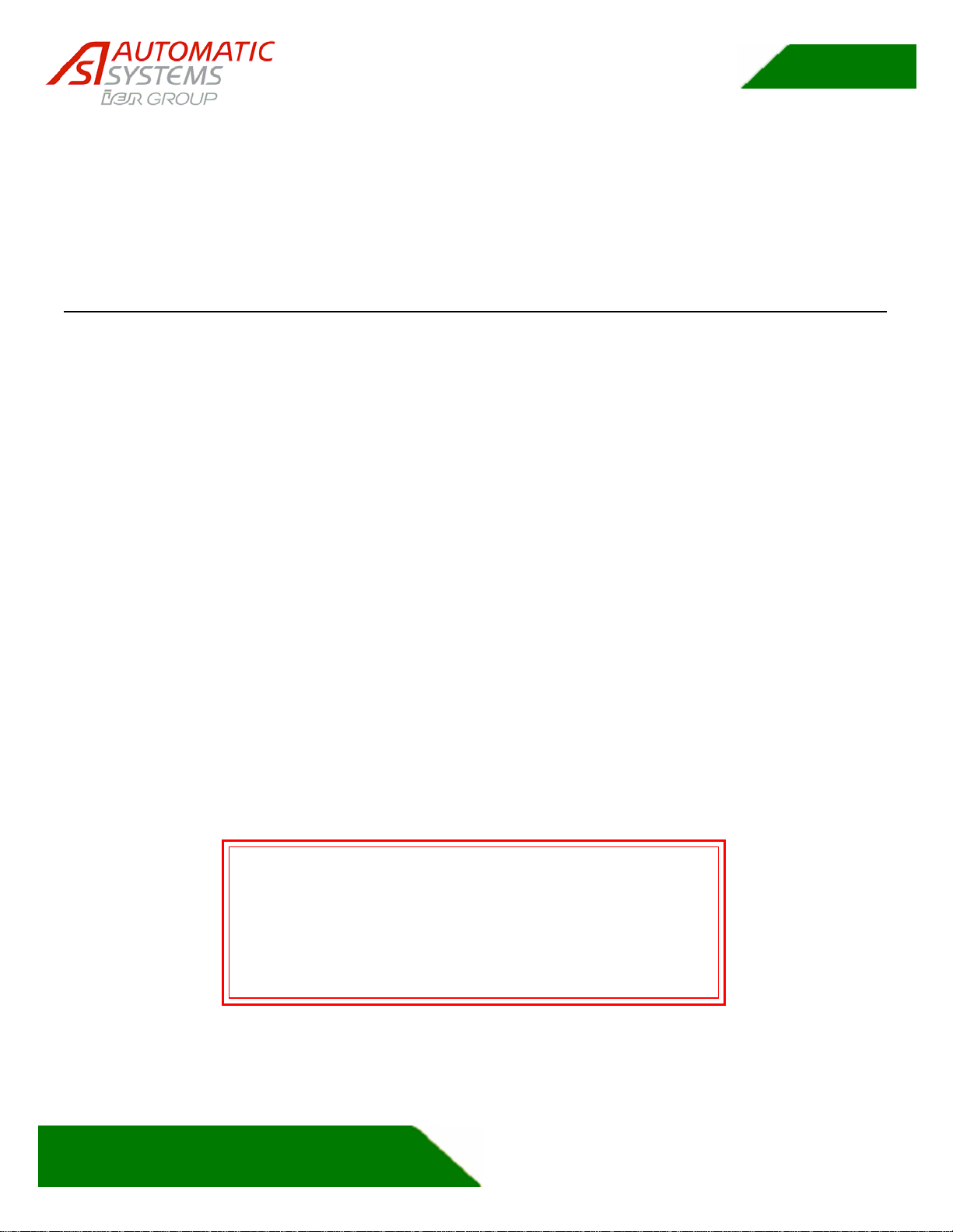
1.6 Baseplates
The following illustrations are showing the six different baseplates for the six different PNG models.
They all share the following elements:
1. There are four holes in every baseplate for the anchor bolt.
2. All baseplates have marked areas where the contractor is permitted to make holes for conduits.
3. The cable conduit maximum height above ground is maximum 2” in the central area.
4. The baseplates must be installed to prevent fire propagation as per UL listing requirement.
5. All holes punched in the baseplate must be properly sealed to prevent fire propagation.
6. Do not use the baseplates as templates. Measure using centerlines only.
Cable conduit maximum
height above ground
is 2" in this area
Sides are the preferred area of entry
Center area
preferred zone
The only drilled holes are the four anchors holes.
Cables Conduit holes must be cut by the contractor.
Hole
(typ.)
Figure 2: 380 Baseplate
Center area
preferred zone
Sides are the preferred area of entry
Cable conduit maximum
height above ground
is 2" in this area
The only drilled holes are the four anchors holes.
Cable conduits holes must be cut by the contractor.
Hole
(typ.)
Figure 3: 390 Baseplate
PNG3XX INSTALLATION MANUAL
NAM-PNG3xx-TM-EN-C.doc
The information contained in this document is the property of Automatic
Systems and is confidential. The recipient shall refrain from using it for any
p
urpose other than the use of the products or the execution of the project to
which it refers and from communicating it to third parties without written prior
agreement of Automatic Systems. Document subject to change without notice.
12
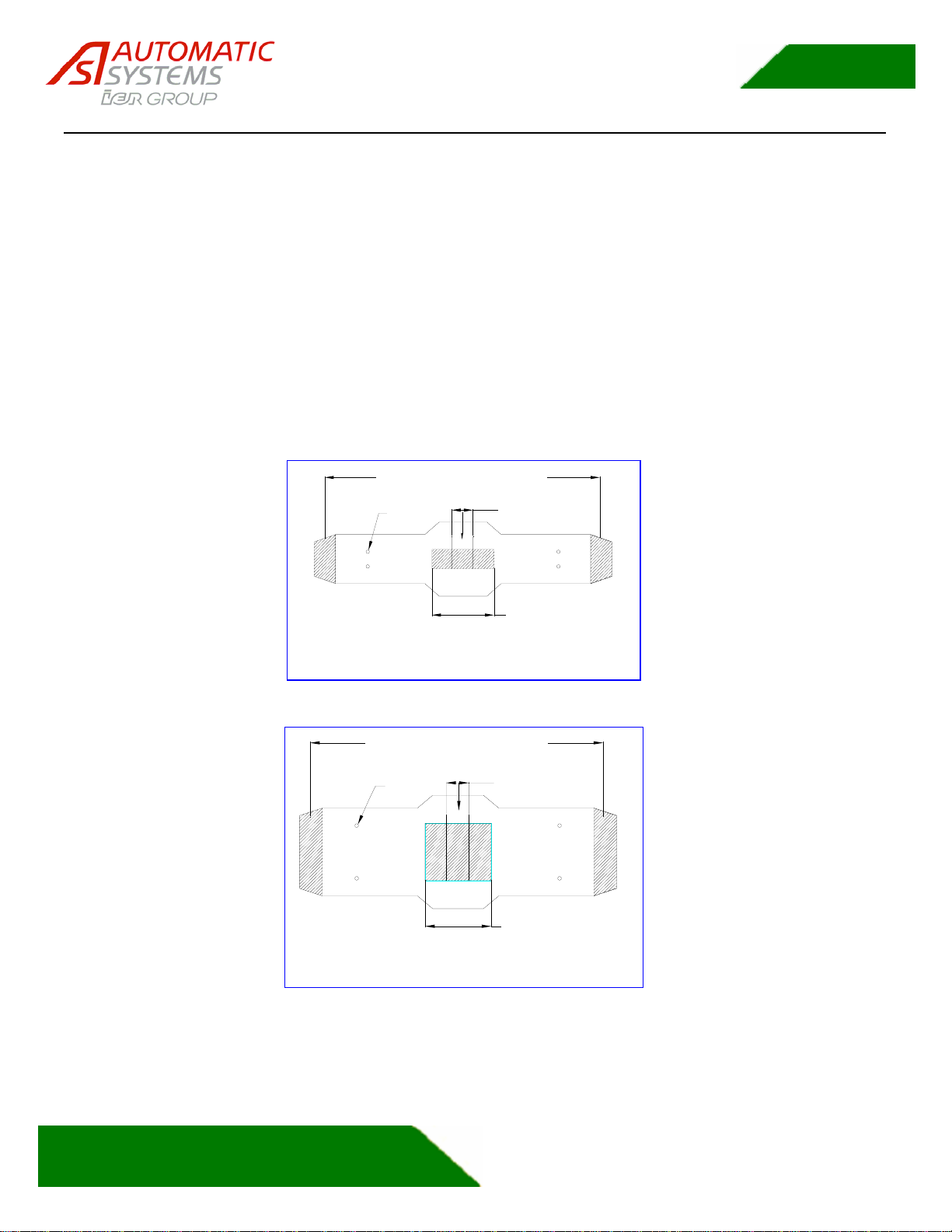
Center area
preferred zone
Sides are the preferred area of entry
Cable conduits maximum
height above ground
is 2" in this area
The only drilled holes are the four anchors holes.
Cable conduits holes must be cut by the contractor.
Hole
(typ)
Figure 4: 381 Baseplate
The only drilled holes are the four anchors holes.
Cable conduits holes must be cut by the contractor.
Holes
(typ.)
Cable conduits maximum
height above ground
is 2" in this area
Sides are the preferred area of entry
Center area
preferred zone
Figure 5: 391 Baseplate
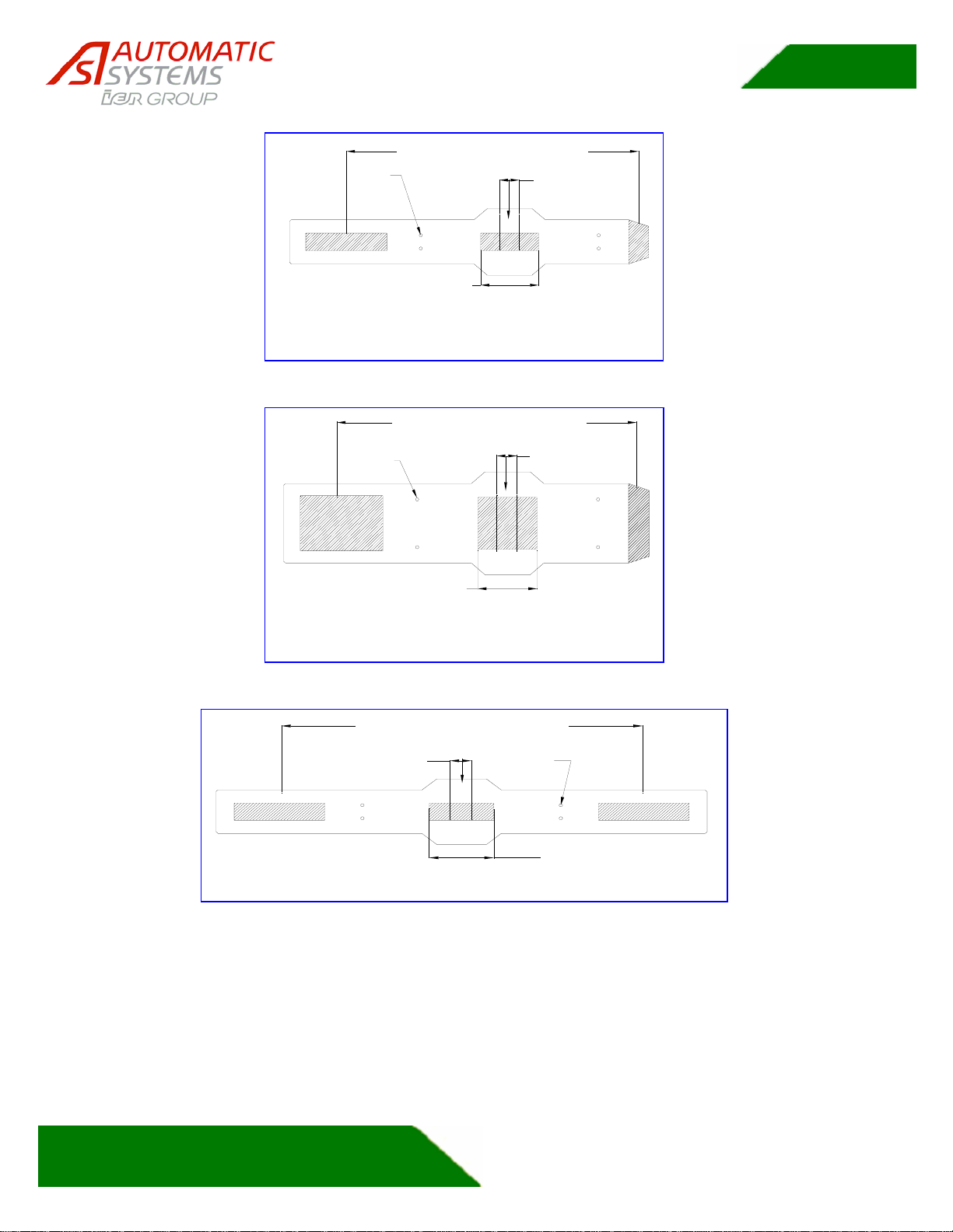
Center area
preferred zone
Sides are the preferred area of entry
Cable conduit maximum
height above ground
is 2" in this area
The only drilled holes are the four anchors holes.
Cable conduits holes must be cut by the contractor.
Holes
(typ)
Figure 6: 382 Baseplate
PNG3XX INSTALLATION MANUAL
NAM-PNG3xx-TM-EN-C.doc
The information contained in this document is the property of Automatic
Systems and is confidential. The recipient shall refrain from using it for any
p
urpose other than the use of the products or the execution of the project to
which it refers and from communicating it to third parties without written prior
agreement of Automatic Systems. Document subject to change without notice.
13
Center area
preferred zone
Sides are the preferred area of entry
Cable conduit maximum
height above ground
is 2" in this area
The only drilled holes are the four anchors holes.
Cable conduits holes must be cut by the contractor.
Holes
(typ)
Figure 7: 392 Baseplate
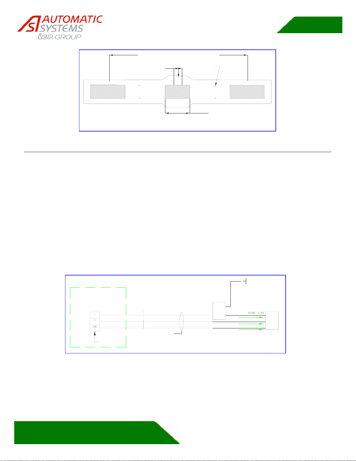
1.7 Emergency Opening
The PNG are designed to be installed in conjunction with emergency systems such as a fire alarm. The
most reliable method to open the doors in an emergency situation is to shut down the power, because in
this case the PNG doors will open using only the normal gravity without any electronic signal involved.
However there is also an electronic input arranged in a fail safe configuration, which can also open the
PNG doors in emergency egress situation. You may select either method for your emergency opening
function. We strongly urge you to verify that the selected method is acceptable with your AHJs.
If you choose to shut down the power to open the PNG in a fire emergency situation, it is essential that the
relay used is not an electronic interrupter. The power must be removed quickly and without slope.
Electronic contactors often remove power in a relatively slow manner in order to reduce arcing of the
contacts and EMI. The use of such device to interface with the PNG optical portals is unacceptable. Use
only mechanical relays with quick transferring contacts. The figure below represents the PNG connection
to the fire alarm systems.
Fire
Alarm
Module 120 V
60 HZ
LINE IN
3 COND /#12 AWG CU.
INDIVIDUAL NEUTRALS
** #10 NEC GROUNDS
WHEN SHARED
3 COND / AWG 12 COPPER
POWER SUPPLY
JUNCTION BOX
GREEN
WHITE
BLACK
LINE
NEUTRAL
GROUND
Fire Alarm
Control Circuit
Emergency
Relay
IN PORTAL
Figure 8: Emergency Opening: Power Shut Down Wiring
PNG3XX INSTALLATION MANUAL
NAM-PNG3xx-TM-EN-C.doc
The information contained in this document is the property of Automatic
Systems and is confidential. The recipient shall refrain from using it for any
p
urpose other than the use of the products or the execution of the project to
which it refers and from communicating it to third parties without written prior
agreement of Automatic Systems. Document subject to change without notice.
14
2. INSTALLATION
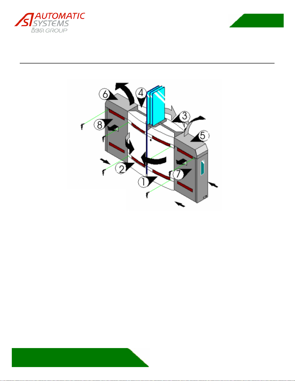
2.1 Move and Unpack Equipment
Legend
1,2,3,4=Side Doors
5,6= Tops
7,8=ExtensionDoors
Figure 9: Hoods and Doors
1. Move the PNG to the installation site using a forklift. Remove PNG from the shipping
crate. Do not twist the units. Excessive torsion on the frame or housing will ruin the unit
alignment.
2. Unlock and open the side doors as shown in Figure 9 (1) to (4). Keys are attached to the
housing with adhesive tape.
3. For PNG381, PNG382, PNG391 and PNG392 models only, also unlock and open the
extension doors (7) and (8) and unlock the tops (5) and (6).
4. Check the condition of the equipment. Although it has been carefully packed, damage
may have occurred during shipping. Carefully document any damage and notify your sale
representative and your shipper. Failure to properly document or notify your sale
representative in a timely manner may adversely affect your damage claim.

PNG3XX INSTALLATION MANUAL
NAM-PNG3xx-TM-EN-C.doc
The information contained in this document is the property of Automatic
Systems and is confidential. The recipient shall refrain from using it for any
p
urpose other than the use of the products or the execution of the project to
which it refers and from communicating it to third parties without written prior
agreement of Automatic Systems. Document subject to change without notice.
15
2.2 Equipment Zones (locations) and Conventions
2.2.1 Conventions and Locations
According to the layout of the components in the PNG, the following terms and locations apply:
Kindly note the A and B directions and relationship to the areas.
MR
SR
MF
LOCATION SR
- MOTOR
INTERCONNECT
JUNCTION BOX
- LOW VOLTAGE
INTERCONNECT
LOCATION MF
- POWER SUPPLY BACKPLATE
- MOTOR INTERCONNECT
JUNCTION BOX
LOCATION MR
- PLC BACKPLATE
- 120 VAC POWER SUPPLY
JUNCTION BOX
PUBLIC (UNSECURED) SIDE
DIRECTION A - ENTRY
SECURE SIDE
DIRECTION B - EXIT
Figure 10: - Areas & Component Location
Electric and electronic boards and connectors are located as follows:
1. Location MF: Power supply backplate (See Figure 11)
2. Location MR: PLC backplate (See Figure 12)
3. Location: SR: Auxiliary connection between master and slave element: (See Figure
13)

PNG3XX INSTALLATION MANUAL
NAM-PNG3xx-TM-EN-C.doc
The information contained in this document is the property of Automatic
Systems and is confidential. The recipient shall refrain from using it for any
p
urpose other than the use of the products or the execution of the project to
which it refers and from communicating it to third parties without written prior
agreement of Automatic Systems. Document subject to change without notice.
16
2.2.2 Location MF (Master Front):
Figure 11 represents the Master unit (right) and Intermediate unit Master Side Power supply backplate.
Figure 11: - Power Supply Backplate
Variable
Frequency
Drive (VFD)
A/K/A
Motor Driver
Variable
Frequency
Drive (VFD)
Circuit Breaker
Slave motor
Interconnection
Junction Box to
Main Circuit
Breaker
Low Voltage
Transformer Fuse
Toroidal
Transformer
PNG3XX INSTALLATION MANUAL
NAM-PNG3xx-TM-EN-C.doc
The information contained in this document is the property of Automatic
Systems and is confidential. The recipient shall refrain from using it for any
p
urpose other than the use of the products or the execution of the project to
which it refers and from communicating it to third parties without written prior
agreement of Automatic Systems. Document subject to change without notice.
17
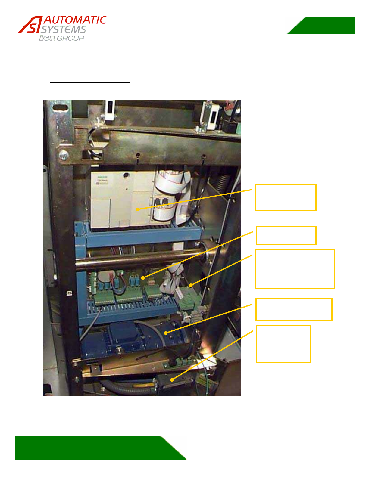
2.2.3 Location MR (Master Rear):
The Figure 12 represents the Master unit (right) and Intermediate unit Master Side PLC backplate.
However note that the motor under the interface board (AS1007) and the low voltage terminal blocks are
present only in an intermediate unit.
Figure 12: PLC Backplate and Main Power Supply Junction Box
Programmable
Logic Controller
PL
C
Interface Board
A
S-1007
120 V AC
Incoming
Power Supply
Junction Box
Low voltage
interconnect terminal
blocks
(Only in Intermediate)
Motor
(Only in intermediate)

PNG3XX INSTALLATION MANUAL
NAM-PNG3xx-TM-EN-C.doc
The information contained in this document is the property of Automatic
Systems and is confidential. The recipient shall refrain from using it for any
p
urpose other than the use of the products or the execution of the project to
which it refers and from communicating it to third parties without written prior
agreement of Automatic Systems. Document subject to change without notice.
18
2.2.4 Location SR (Slave-Rear):
2.2.4.1 Slave Unit
Figure 13 represents the slave unit (left) SR location only.
Figure 13: –Slave Unit Low Voltage & Motor Interconnection
Low voltage
interconnect
terminal blocks
(may appear
slightly different)
Slave unit motor
interconnection
junction box
[On intermediate unit-
Slave side- it is
behind the PLC
bac
k
p
l
a
te]

PNG3XX INSTALLATION MANUAL
NAM-PNG3xx-TM-EN-C.doc
The information contained in this document is the property of Automatic
Systems and is confidential. The recipient shall refrain from using it for any
p
urpose other than the use of the products or the execution of the project to
which it refers and from communicating it to third parties without written prior
agreement of Automatic Systems. Document subject to change without notice.
19
2.3 Preliminary Site Work
•Position the equipment according to the site's general layout. Be careful not to bend or twist the
unit during transport or positioning.
•Place the stainless steel baseplates according to the layout, Space the units as per layout (The
centerline of the baseplate can be used as a template). You may temporarily remove the
baseplates in order to determine the conduit holes required and punch the conduit entrance holes.
Figure 14 represents a PNG typical layout.
36"
23"
23"
13 3/16" 19 1/16"
31 1/2"
8 1/4"2 3/8"
EXIT (B)
ENTRANCE (A)
9 1/4"
5 3/8"
9 1/4"
5 7/16"
PNG-380
LEFT PNG-380
INTER PNG-390
INTER. HYB.
LEFT
PNG-390
RIGHT
EXIT (B)
ENTRANCE (A)
EXIT (B)
ENTRANCE (A)
15 3/4" 50"
36 3/16" 39 1/8" 55 1/16"
6 5/16" 12 3/16"
5 5/16"
5 5/16"
31 1/2"
15 3/4"
50"
Figure 14 – PNG LAYOUT
•Mark and drill the anchor holes in the floor according to the specifications in the Installation Plans. Ensure that
the diameters of the holes are appropriate for the expansion bolts being used. The bolts provided can be
replaced by others that are better suited for a specific flooring

PNG3XX INSTALLATION MANUAL
NAM-PNG3xx-TM-EN-C.doc
The information contained in this document is the property of Automatic
Systems and is confidential. The recipient shall refrain from using it for any
p
urpose other than the use of the products or the execution of the project to
which it refers and from communicating it to third parties without written prior
agreement of Automatic Systems. Document subject to change without notice.
20
Figure 15 - Anchoring Bracket
•The included expansion anchors may not be suitable for every application. It is important that you use the
correct anchors for your specific needs. For example, if you are anchoring to a thin slab that has access
underneath, you may need to through bolt the unit. Another example involves wooden flooring. Obviously,
expansion anchors are not appropriate to secure a PNG to a wood floor. Wood flooring may require cross
braces to “stiffen” the floor from flexing. The PNG must be secured in place on a rigid base. Otherwise the
cabinets will not always be level and plumb. This can affect the photocell alignment and can also affect the fail
safe opening of the glass barriers.
1/2" Diameter
Drill Bit (masonry)
This manual suits for next models
8
Table of contents
Other Ier Turnstile manuals


