Automatic Systems TriLane TL2 User manual

TriLane TL2
www.automatic-systems.com
TRIPOD TURNSTILE TL2
Quick Start Guide (QSG)
Installation Instructions and Getting Started
(Translated from the original French version)
Rev. 03

p. 2/11
TL2-QSG-EN-03
1. INTRODUCTION
Thank you for choosing a TriLane tripod turnstile designed and manufactured by Automatic Systems.
We are sure that your purchase will fully meet your requirements for many years, and, to that end, we would strongly
advise you to read this manual carefully.
It will assist you with unpacking, installing, commissioning and maintaining your appliance.
Proper installation and regular maintenance will ensure the proper operation of the appliance and will significantly
increase the life of its components.
Although this manual has been prepared with great care, some information may seem erroneous
or unclear to you. In this case, please do not hesitate to contact us with your remarks or
questions.
A technical manual with detailed information on the TL2 product and on the AS1635 logic board
is available on our Partnerweb (https://partnerweb.automatic-systems.com) or flashing /
scanning the attached QR Code.
2. SAFETY WARNINGS
о This manual must be available to all persons who are required to work on the equipment, such as installers,
maintenance operators, end users, etc.
о Tripod turnstiles are designed to control the access of persons to a given area, and cannot be used for another
purpose without risk to the user and to the integrity of the equipment.
Automatic Systems cannot be held liable for damage resulting from improper use of the equipment
о Do not install this equipment in an explosive area.
о Do not add any non-approved accessories (contact between different metals can cause a battery effect that will
reduce the corrosion resistance of the equipment).
о The contractor shall comply with local regulations when installing the equipment.
о All operations on the equipment must be carried out by qualified personnel. Any work on this product that is
unauthorized or carried out by an unqualified technician will automatically void the manufacturer’s warranty.
о Access to the mechanism must be reserved for staff who are aware of the electrical and mechanical risks incurred in
case of negligent handling.
о For any operation that does not require the equipment to be powered up, turn off the power at the distribution panel
or at the main switch (Fig. 2, page 4).
о Any internal component that is likely to conduct electricity or that can move must be handled with caution.
о The use of antistatic gloves or bracelets (Electronic Static Discharge) is essential when handling electronic printed
circuit boards, at the risk of the warranty being voided.
о The equipment is configured in a “minimal risk” mode for users. Parameters should only be changed by qualified
personnel with full knowledge of the consequences, and any such changes shall in no way entail any liability on the
part of Automatic Systems.
о If the product is resold, it is the responsibility of the seller to ensure, for each piece of equipment that is offered,
sold and installed, that its foreseeable environment and use take into account the technical characteristics of the
equipment and comply with these requirements.
The seller shall defend and indemnify Automatic Systems from any claims against Automatic Systems due to the
seller’s failure to comply with the above obligations.
The information contained in this document is the property of Automatic Systems and is confidential. The recipient shall refrain from using this information for any purpose
other than the use of the products or the execution of the project to which it refers and from communicating it to third parties without prior written agreement of Automatic
Systems. The document is subject to change without notice.

p. 3/11
TL2-QSG-EN-03
3. GENERAL SYMBOLS
The following symbols are used in this manual or as labels on the equipment:
This symbol is used to highlight a tip that may help you to better understand the product.
This symbol is used to highlight an important instruction for the correct use and/or maintenance of the
product.
This symbol is used to highlight a risk of electric shock or electrocution.
This symbol is used to highlight a risk of cutting yourself.
This symbol is used to identify the principal ground connection point.
(Either in the form of an affixed label or directly engraved on a mechanical part)
13
This symbol is used to indicate the tool required for the relevant operation.
This symbol indicates that the equipment conforms to European standards and directives.
This symbol indicates that the equipment must be disposed of in accordance with the applicable
European Directives (DEEE 2012/19/EU).
Model
Mfg Date
Phases
Volts
kg
Hz
A
Item
Serial
SN
MADE IN BELGIUM
www.automatic-systems.com
TL2P
xx/xx/18
230
E/TL2P/002
18-TL2P-B0000
1
2
65
50/60
Product identification label showing the equipment type, the production
date, the voltage, the weight and the serial number and the reference code.
4. GENERAL
4.1. GENERAL CONDITIONS OF USE
Your TriLane tripod turnstile has been designed to operate in any kind of climatic environment from -10°C to +50°C,
with up to 90% of relative humidity.
4.2. PACKAGING
In most cases, your turnstile will be delivered in a cardboard box attached to a wooden pallet.
A bag containing the keys and attachments for the last arm is attached to one of the turnstile arms.
The last arm is located inside the turnstile, under the cover.
4.3. UNPACKING
When the equipment arrives on-site, please check that it is complete and in good condition.
If for some reason damage has occurred during transport, please check that the transport document is in good
condition and, where necessary, report the incident to Automatic Systems.
The information contained in this document is the property of Automatic Systems and is confidential. The recipient shall refrain from using this information for any purpose
other than the use of the products or the execution of the project to which it refers and from communicating it to third parties without prior written agreement of Automatic
Systems. The document is subject to change without notice.

p. 4/11
TL2-QSG-EN-03
4.4. GENERAL VIEW
4:3
4:1 4:2
4:4
4:8 4:5
4:11
4:7
4:124:10
4:6
4:9
A
Fig. 1 - Location of components
Ref.: Designation: Ref.: Designation:
4:1 Painted steel box. 4: 7 Electrical circuit board, left (Power supply).
4: 2 Aluminum front end box (A). 4: 8 Functional pictogram (Option).
4: 3 Aluminum rear end box (B). 4: 9 Fixings provided by dowels.
4: 4 Top cover in brushed stainless steel. 4: 10 Lock.
4: 5 Drive assembly. 4: 11 Non-contact reader installed under
protection screen (option).
4: 6 Stainless steel fixed arm 4: 12 Electrical circuit board, right (control logic).
As a convention and a general rule, the user will be considered to be in direction "A" when the tripod is
on his right side, and in direction "B" when the tripod is on his left side.
4.5. LOCATION OF THE ELECTRICAL COMPONENTS
4:16 4:21
4:15
4:184:17 4:19 4:20
4:22
Ref.: Designation:
04:15 Support for electronic devices
04:16 DIN rail
04:17 Power supply 24 VDC - 4 A
04:18 Main switch:
If you open the
casing, turn off the equipment
by switching off the main
switch.
04:19 Earth terminal
04:20 Terminal block stop.
04:21 Protective film.
04:22 Motor control board (option)
Fig. 2 - Electrical PC board, left
The information contained in this document is the property of Automatic Systems and is confidential. The recipient shall refrain from using this information for any purpose
other than the use of the products or the execution of the project to which it refers and from communicating it to third parties without prior written agreement of Automatic
Systems. The document is subject to change without notice.

p. 5/11
TL2-QSG-EN-03
4:23
4:25
4:24
Ref.: Designation:
04:23 Support for electronic devices
04:24 Control logic AS1635
04:25 Protective film.
Fig. 3 - Electrical card, left
4.6. IN THE EVENT OF POWER FAILURE
Depending on the type of mechanics installed inside the unit, the TriLane tripod turnstile can either release or not
release passage if power to the equipment is lost. This unlocking principle in the case of an emergency situation
is referred to as "anti-panic". The dropped arm has to be manually place back to the horizontal position by a turret
rotation. On the motorized version, a turret rotation is automatically performed at power on.
5. INSTALLATION
5.1. RECOMMENDED TOOLS
13
• Standard electrical tools.
• Flat spanner set.
• Set of Allen keys.
• Spirit level.
• Hammer drill + concrete drill bit - Ø 15 x 100
• Standard protective equipment: gloves, goggles, hard hat and safety shoes.
5.2. PRELIMINARY WORK
• The turnstile has been specially packaged for transport. Bring the material to the installation site with the help of
a forklift truck and remove the packing material.
• Unlock the locks (4:10) and open the cover (4:4). The keys are supplied as accessories in a separate bag.
1 1
2
4:10
4:4
Fig. 4 - Removing the cover.
The information contained in this document is the property of Automatic Systems and is confidential. The recipient shall refrain from using this information for any purpose
other than the use of the products or the execution of the project to which it refers and from communicating it to third parties without prior written agreement of Automatic
Systems. The document is subject to change without notice.

p. 6/11
TL2-QSG-EN-03
• Lift and remove the 2 end boxes (4:3 and 4:2).
4:3 4:2
Fig. 5 - Removing the front and rear end boxes
• Check the condition of the material - although it has been carefully packed, damage may have occurred during
transport.
5.3. GENERAL DIMENSIONS AND INSTALLATION DRAWING
Arm height X
Dropping arm 750
Standard arm 755
min. 100*
AAA
BBB
Ø60
Ø15*
160 37.537.5
235550235235
40
1300
X
880 210210
550
80
Power supply and connection wiring inlet, can be through right or left end box
EXPANSIBLE ANCHOR B15/30
-/3413/000
(Suggested reference (M10))
Ø 60 mm PVC SHEATH.Concrete
Wiring to provide for:
230 V single phase power supply + ground, in 3G2.5 ²
IP CABLE (Ethernet) STP CAT.5
* Dimensions according to standard Automatic Systems anchoring.
The information contained in this document is the property of Automatic Systems and is confidential. The recipient shall refrain from using this information for any purpose
other than the use of the products or the execution of the project to which it refers and from communicating it to third parties without prior written agreement of Automatic
Systems. The document is subject to change without notice.

p. 7/11
TL2-QSG-EN-03
Fig. 6- General dimensions and installation plan (plan CH9594)
5.4. SITE PREPARATION WORK
This is basically the following:
• Study the set-up and positioning of the equipment according to the general layout of the site.
• Drill the holes in the floor according to the specifications of the Fig. 6, page 7.
• Be sure to drill the holes with a diameter suitable for the expandable dowels that you are going to use (recommended
type: model B15/30, ref. -/3413/000).
• Check the correct location of the cable passage at 80 mm from the hole of the mounting holes (see Fig. 6).
• Prepare the passage for the electrical control cables of the Central Control Station (not supplied) and the main
supply cables (230V single-phase + earth, i.e. 3G x 2.5). Provide 1.5 metres extra.
If you add any device to the front or rear end boxes of the turnstile that could ignite (see EN60950 standard, paragraph
4.4.5), ensure that the installation surface is non-flammable.
5.5. INSTALLING THE TURNSTILE
• Position the turnstile precisely.
• Ensure that the turnstile remains firmly fixed to the ground by tightening the expandable dowels. Ensure that the
cables can pass through.
• Make sure that all the housings of the battery are perfectly aligned and horizontal. If needed, add shims between
the housings and the floor to ensure that they are perfectly level.
5.6. INSTALLING THE STAINLESS STEEL ARM (VERSION WITH FIXED ARMS)
5:1
4:6
5:2
LOCTITE
243
Blue
Fig. 7 - Installing the stainless steel arm
• Put the arm (4:6) in place and push it into the housing until it stops.
• Align the threaded hole in the arm with the hole in the turret.
• Install the fan washer (5:1).
• Apply one drop of Loctite* 243 (blue) to the screw thread (5:2), and tighten.
• With the dropping arm option installed, the 3 arms are installed from factory.
The information contained in this document is the property of Automatic Systems and is confidential. The recipient shall refrain from using this information for any purpose
other than the use of the products or the execution of the project to which it refers and from communicating it to third parties without prior written agreement of Automatic
Systems. The document is subject to change without notice.

p. 8/11
TL2-QSG-EN-03
5.7. ELECTRICAL CONNECTIONS AND INITIAL POWER-UP
4:174:184:19
IN
Fig. 8 Left electronic support
• The electrical connections must be carried out in accordance with the diagram provided with the equipment.
• Make sure that the power supply cables are not live. All the internal connections have already been made in the
factory.
• Cut off the excess cable length if necessary; connect the 230V single-phase power supply wires to the main switch
terminals (4:18) and the ground wire to the adjacent terminal (Fig. 8, page 8 (4:19)).
• Check that the equipment is properly grounded (casing, etc.)
• Make any other connections according to the specifications of the installation (control cables, etc.)
• Check that there are no cables that could break or be damaged by the movement of the mechanism, and that they
all are properly held in the trunking or wire clamps provided for this purpose.
5.8. CHECKLIST
• Check if all wires are firmly connected to their respective terminal blocks.
• Check the free movement of the tripod when the power to the equipment is turned off in the case of a mechanical
system with an anti-panic device ("type 5" or "type 3").
• Check if all screws and nuts have been tightened firmly.
• Check that you have not left any tools inside the gate.
• Remove any foreign bodies from inside the casing (packaging, scraps etc.), and clean it.
• Turn on the equipment by switching the main switch (4:18) [to the ON position].
• Put in place the rear and front end boxes (Fig. 5, page 6 (4:3) and (4:2)).
• Install and lock the cover (Fig. 4, page 5(4:4)).
• Check the functionalities (Pictograms, locking mechanism, fraud detection.. performing a few passages in both
directions.
The tripod turnstile is now operational. All the settings have been made in the factory at the time of the working tests.
Some additional adjustment could nevertheless be necessary as a result of transport or handling during assembly. In
such cases, refer to the Technical Manual.
5.8.1. Functional test
The tripods are delivered from factory on a controlled mode configuration in both direction (passage authorisation
through a reader or push button).
Five push buttons located on the AS1635 control board allow to modify the configuration, choosing between free/
controlled/ locked mode on both direction:
• Press the central OK button (= SW6) for 2 seconds to switch to the Configuration mode. To exit this mode, press
the OK button again for 2 seconds or wait for 1 minute.
• Briefly press the Right button (SW3) to display the sub-menu, beginning with md-A.
• Use the Up (= SW4) and Down (= SW5) buttons to navigate within the sub-menu and access md-b
• Press the right button (SW4) again to display the contents of the parameters CLOS , FrEE or CtrL and the Up
and Down button to modify the setting. Confirm the new setting with OK (SW6):
The information contained in this document is the property of Automatic Systems and is confidential. The recipient shall refrain from using this information for any purpose
other than the use of the products or the execution of the project to which it refers and from communicating it to third parties without prior written agreement of Automatic
Systems. The document is subject to change without notice.

p. 9/11
TL2-QSG-EN-03
SW4
SW6
SW2 SW3
SW5
Fig. 9 Push button for programming
2 sec.
2 sec.
2 sec.
1
2
3
2 sec.
4
2 sec.
1
2
4
3
In standby condition and controlled mode, the Up (SW4) and Down (SW5) buttons can be used to deliver passages
authorization respectively in A or B directions. This feature will be appreciated by the technician in charge of
maintenance or diagnostic job. If the dropping arm option is installed, the Right button (SW3) allows to make a test;
the arm in the horizontal position will drop. Please down load the AS1635 technical manual for more details.
5.9. MAINTENANCE OF SURFACES
To retain the surface appearance and avoid any oxidation deposits or marks, it is strongly recommended to regularly
treat the stainless steel surface with a product specially designed for this purpose.
Automatic Systems can provide an approved product under reference -/6031/000.
Automatic Systems reserves the right to deny warranty coverage in the case of an apparent lack of maintenance.
The information contained in this document is the property of Automatic Systems and is confidential. The recipient shall refrain from using this information for any purpose
other than the use of the products or the execution of the project to which it refers and from communicating it to third parties without prior written agreement of Automatic
Systems. The document is subject to change without notice.

p. 10/11
TL2-QSG-EN-03
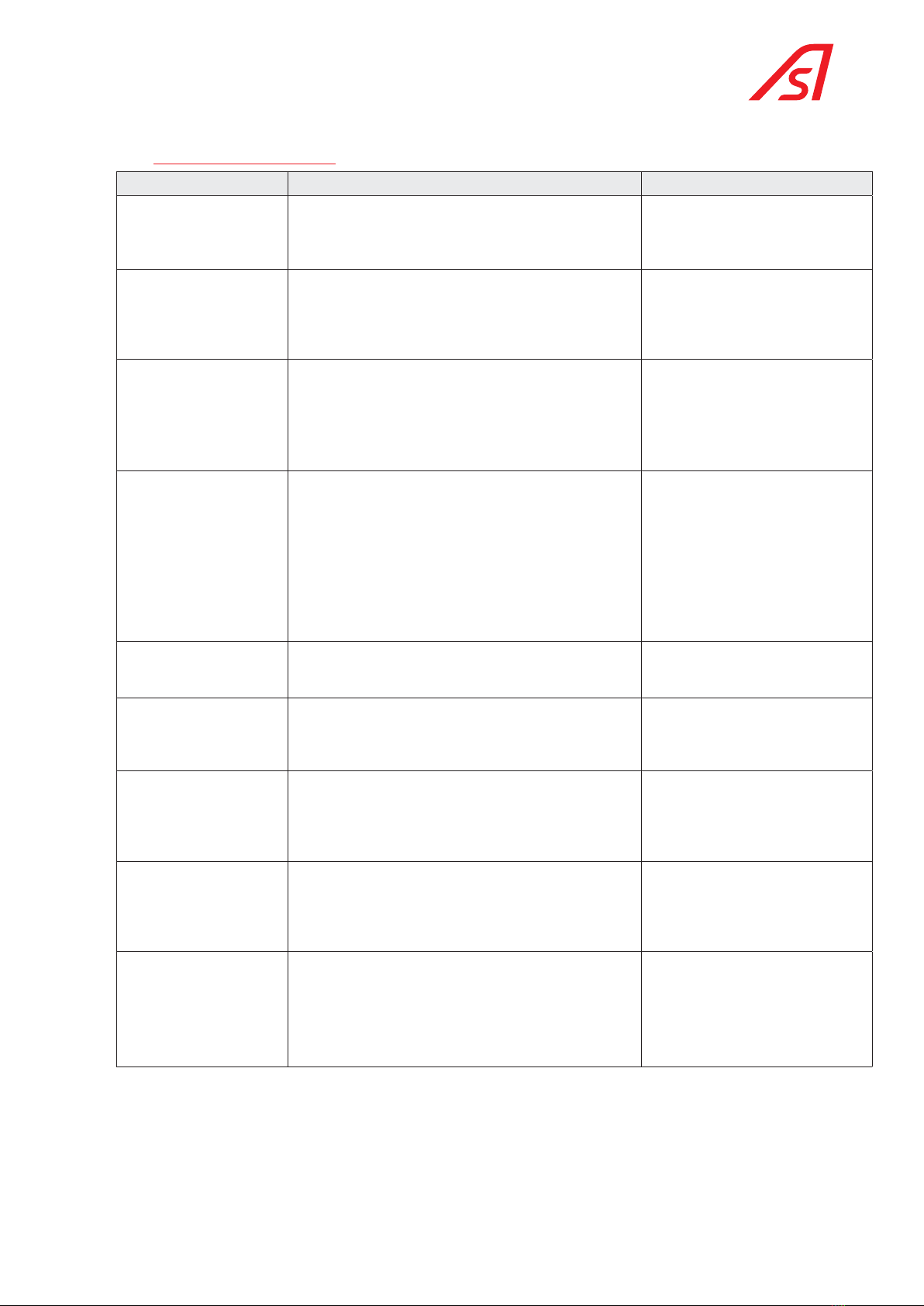
5.10. FAULT DIAGNOSIS
Failure description Possible cause Comment
The Trilane is not powered
(pictogram not lit, drive
not lit, free passage in
both directions, etc.)
Remove the cover and check the 230 VAC connection and
the position of the main circuit breaker. Check the correct
24 VDC supply voltage.
In the A5/B5 configuration, the de-
energised TriLane is free in both
directions of passage.
A pictogram is not lit. On the AS1635 circuit board, check the connection of
the CN10 connectors (pictogram direction A) and CN11
(pictogram direction B).
Replace the pictograms if necessary.
CN10(or 11)-1 red
CN10(or 11)-2 green
CN10(or 11)-3 blue
CN10(or 11)-4 white
CN10(or 11)-5 0V ref
The passage
authorisation is not taken
into consideration.
Using the HMI, check that the TriLane is not in blocked
mode.
Check the connection between the reader and the AS1635
circuit board (24 VDC pulse in CN2-1 for authorisation in
the A direction and in CN2-2 for authorisation in the B
direction).
Default configuration of the inputs,
can be modified via the PC interface.
The TriLane does not lock
itself (in direction A or
direction B)
Check the programmed operating mode in direction A and
B via the HMI (free, controlled, blocked).
Check that the TriLane is not in Emergency mode
(connection between CN1.3 and 4 for normal operation).
Check the supply voltage of the electro-magnet, between
CN5-1 and CN5-2 (direction A) or CN5-3 and CN5-4
(direction B).
If the electro-magnet is functioning correctly, check the
locking mechanism
Note: the 24 VDC voltage is only
applied during the first moments The
holding voltage is reduced to prevent
the electro-magnet from heating up.
The turret will not re-lock
during rotation.
Check the operation of the angular sensor and the
connecting cable (CN17 on the AS1635 circuit board).
In the case of an angular sensor
problem, an error appears on the HMI
display.
The TriLane does not
operate and the LED LD1
on the AS1635 circuit
board is off.
The AS1365 control circuit board is not powered with
24 VDC. Check the 24 VDC power supply module and the
connection cable to CN1-1 and CN1-2.
The TriLane does not work
and the LED LD6 on the
AS1635 circuit board is off.
The program is not running. Turn off the power to
reinitialise the program or press the Reset button (see the
position in the technical manual of the AS1635).
As a last resort, replace the AS1635 control circuit board.
If the control circuit board is
replaced, a new calibration operation
will be required at power on. Refer to
the unit test chapter in the AS1635
manual.
The horizontal arm does
not fall in the case of
a power failure or an
emergency. (Dropping-arm
option retained)
Check the condition of the two actuating springs of the
arm release mechanism (See the technical manual)
The motor does not
engage (motorisation
option retained)
Check that the CAN bus cable W6 is connected to the CN13
connector of the AS1635 circuit board.
Check the connection between the motor circuit board AS
1636 and the motor.
If necessary, replace the motor circuit board or the gear
motor.
The information contained in this document is the property of Automatic Systems and is confidential. The recipient shall refrain from using this information for any purpose
other than the use of the products or the execution of the project to which it refers and from communicating it to third parties without prior written agreement of Automatic
Systems. The document is subject to change without notice.

p. 11/11
TL2-QSG-EN-03
ISO
9001
Quality
Managment
bsi.
Made in WAVRE,
Date: 2019.07.09
Name: Michel TOUSIGNANT
Function: R&D Director
EC declaration of conformity
We, undersigned,
AUTOMATIC SYSTEMS s.a.
Avenue Mercator, 5
1300 Wavre
BELGIQUE
Herewith declare that the following machine
Tripod turnstile
TL1, TL2
is in accordance with the conditions of the following Directives, standards and other specifications:
•Machinery Directive 2006/42/CE.
•Low-voltage Directive 2014/35/UE.
•Electromagnetic compatibility Directive 2014/30/UE.
•Directive RoHs (Restriction of Hazardous Substances) 2011/65/EU.
•EN 12100:2010: Safety of machinery – General principles for design - Risk assessment and
risk reduction (ISO 12100:2010).
•IEC 60204-1 / A1 : 2009: Safety of machinery - Electrical equipment of machines -
Part 1: General requirements.
•EN 61000-6-3 / A1 : 2011: Electromagnetic compatibility (EMC). Generic standards. Emission
standard for residential, commercial and light-industrial environments.
•IEC 61000-6-2 : 2016: Electromagnetic compatibility (EMC). Generic standards. Immunity
standard for industrial environments.
International & Headquarters
AUTOMATIC SYSTEMS SA
Email: [email protected]
Tel.: +32.10 23 02 27
Fax.: +32.10 86 22 90
Belgium
Wallonia-Brussels
Tel.: +32 70 22 44 66
Fax.: +32 10 86 22 90
Email: [email protected]
Belgium
Flanders
Tel.: +32 70 22 44 66
Fax.: +32 3 88 700 76
Email: dnv[email protected]
Canada
Tel.: +1 450 659 0737
Fax.: +1 450 659 0966
Email: [email protected]
China
Tel.: +86 512 5383 0561
Email: [email protected]
Deutschland
Tel.: +49 2303 553 4040
Fax.: +49 2303 553 4049
Email: [email protected]
France
Tel.: +33 1 30 28 95 53
Email: [email protected]
Spain
Tel.: +34.70.22.44.66
Fax.: +32.10.86.22.90
Email: [email protected]
United Kingdom
Tel.: +44 (0) 1604 654 210
Fax.: +44 (0) 1604 654 110
Email: [email protected]m
United States
Tel.: +1 450 659 0737
Fax.: +1 450 659 0966
Email: [email protected]
Latin America
Tel.: +1 450 659 0737
Fax.: +1 450 659 0966
Email: [email protected]
The information contained in this document is the property of Automatic Systems and is confidential. The recipient shall refrain from using this information for any purpose
other than the use of the products or the execution of the project to which it refers and from communicating it to third parties without prior written agreement of Automatic
Systems. The document is subject to change without notice.
Table of contents
Other Automatic Systems Turnstile manuals

Automatic Systems
Automatic Systems TriLane TL Series User manual

Automatic Systems
Automatic Systems TR491 User manual

Automatic Systems
Automatic Systems SL930 User manual

Automatic Systems
Automatic Systems SmartLane User manual

Automatic Systems
Automatic Systems SMARTLANE SL 90X User manual

Automatic Systems
Automatic Systems TR450 User manual

Automatic Systems
Automatic Systems SMARTLANE SL 90 Series User manual

Automatic Systems
Automatic Systems TriLane TL1 User manual