IES 4416 User manual

Revision RB16
IES 4416
Onbord LED + CAM Controller
SYSTEM DESCRIPTION
Mobile ruggedized supply and control unit for up to 20 LED illumination heads
and 10 high speed video cameras.

Contents
1 OVERVIEW......................................................................................................................3
1.1 Mounting information.............................................................................................................4
2 CONNECTORS AND FRONT PANEL ELEMENTS........................................................5
2.1 MAIN connector.....................................................................................................................5
2.2 CTL/STS connector...............................................................................................................6
2.3 AUX connector......................................................................................................................6
2.4 LED head connector..............................................................................................................7
2.5 LED status markers...............................................................................................................7
2.6 Front panel button.................................................................................................................7
2.7 CAM1 to CAM10 port connector............................................................................................8
2.8 Trailing cable connector Lemo 5B.........................................................................................9
3 FUNCTIONAL DESCRIPTION.......................................................................................11
3.1 Unknown IP.........................................................................................................................11
3.2 Setup light...........................................................................................................................11
3.3 Starting the light...................................................................................................................11
3.4 SYNC and CONT modes.....................................................................................................12
3.5 External sync input..............................................................................................................12
3.6 Special Functions................................................................................................................12
3.7 Device shutdown timer........................................................................................................13
4 DIAG4400-SOFTWARE.................................................................................................14
4.1 Finding and connecting LED-Controllers.............................................................................14
4.2 CMD-Tab.............................................................................................................................16
4.3 Config-Tab...........................................................................................................................16
4.4 Battery-Tab..........................................................................................................................18
4.5 IP-Settings -Tab...................................................................................................................18
4.6 Status -Tab..........................................................................................................................19
5 CE CONFORMITY.........................................................................................................21

1 Overview
This onboard LED + CAM controller can supply energy and can control up to 20 LED illumination
heads and up to 10 high speed video cameras. It is made for installation on bord of a vehicle and
may be used in crash testing scenarios. It contains internal rechargeable batteries.
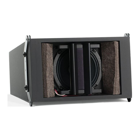
In its standard version it has a standard KT (Minidau) footprint. As an option, one or two "balconys"
(see photograph, shown is the 5B balcony) below are available, that allow connection of a small or
a full size trailing cable (Lemo 3B or Lemo 5B connectors).

1.1 Mounting information
The drawing below shows the main measures. From the bottom threads at least 6 should be used.
We also recommend the good practise of having a stopping edge on the users mounting plate,
which can take the acceleration force.
Bottom view
12 Gewinde M5, Einschraubtiefe max. 8 mm
12 threads M5, depth max. 8 mm
110
99
LED-Controller
4416
MF01
ON / OFF
RDY
SYN
ETH
TRG
90%
70%
50%
30%
LED 1 LED 2
CTL/STSMAIN
CAM 8CAM 7
CAM 5
CAM 2
CAM 4CAM 3
CAM 1
CAM 9
CAM 6
CAM 10
LED 7
LED 4 LED 5 LED 6
LED 3
LED 8 LED 9
LED 10
46 270
27016 30
Unverschobene KT-Befestigung
86,586,5
55,5
110
25,5
30

2 Connectors and Front Panel elements
All connectors and user interface elements are located on the front panel.
2.1 MAIN connector
The MAIN connector is used to connect this device to the user´s existing infrastructure.
Connections are:
Power supply to internal charger
Ethernet for communication
Trigger input
Sync input
The pinout is given in the table below.
Connector type in front panel: Lemo EGA.2B.318
Connector type for user cable: Lemo FGA.2B.318
Pin Signal Remark
1 Ethernet A-
2 Ethernet D-
3 Ethernet B-
4 Ethernet B+
5 Ethernet C+
6
7 +CHGSUP Charger-Input 40-48 V, 1 A
8 +CHGSUP as above
9 SYNC+
10 SYNC-
11 -CHGSUP Device-GND and Charger-GND
12 -CHGSUP as above
13 Ethernet A+
14 Ethernet D+
15 Ethernet C-
16
17 +T0
18 -T0
Case
The input signals SYNC and T0 are of type RS-485. They are pulled to their respective quiet
voltage levels by internal pullup resistors and therefore may be left open, if unused.

These inputs also accept TTL input signals. These must be referenced to GND. This table shows,
how to connect a TTL sync signal to the MAIN connector:
TTL sync out from user´s equipment MAIN Pin 9
TTL GND from user´s equipment MAIN Pin 11
It would be possible to signal T0 with a closing contact between pins 17 and pin 11 - however this
is not recommended, because it is an RS-485 input and not an explicit contact input. But it´s ok for
testing purposes.
2.2 CTL/STS connector
The CTL/STS connector has control and status signals for exchange with external equipment. The
signals are optoisolated and the couplers have internal current limiting circuity, so they can be
driven from sources between 5 V and 24 V without additional resistors. Functions provided:
START signal input to start the light
READY output to signal ready status
Remote front panel button control input
There is also an isolated 5 V voltage source provided on this connector. It makes it easy to use the
optoisolated inputs from closing contacts.
The pinout is given in the table below.
Connector type in front panel: Lemo EGG.1B.308
Connector type for user cable: Lemo FGG.1B.308
Pin Signal
1 Opto-Start K
2 ISO 0V
3 Opto RDY C
4 Opto RDY E
5 ISO +5 V
6 Opto Start A
7 Opto Setup light A
8 Opto Setup light K
2.3 AUX connector
The AUX connector is used for user specific extensions. There is no general description available
or possible. In case of devices with no trailing cable "balcony", this connector is typically used to
feed in the camera power.

2.4 LED head connector
The LED illumination heads are connected to the LED 1, LED 2 , ... output connectors. Each
output connector can supply two LED heads, or one double LED head. Each output connector has
one temperature supervising input channel.
If (downgraded) devices are not fully equipped with LED ports, then the lower connector numbers
ar functional (starting at LED1) and the higher numbers are not functional.
The pinout is given in the table below.
Connector type in front panel: Lemo EGG.1B.306
Connector type for user cable: Lemo FGG.1B.306
Pin Signal
1 LED A1
2 LED K1
3 LED A2
4 LED K2
5 NTC a
6 NTC b
Case Screen
2.5 LED status markers
The status markers indicate
Charge level of internal batteries
Ethernet communication activity
Sync input signal present
Controller ready status
During charge (when external power supply is attached to MAIN connector) the highest charge
level LED blinks. This indicates, charging takes place. The charging is complete, if all charge
indication LED´s are ON.
Ethernet indicator is normally ON, and is blanked for a moment, if a command is received and
processed.
Sync LED is ON, if a valid external sync signal is recognized.
Controller ready status is signalled, if battery is in good condition and no temperature is higher than
the "ready level". See operating instructions for more on ready signalling.
2.6 Front panel button
The front panel button provides these functions:

Switch ON the device (press short)
Switch ON or OFF the light (press 1/2 second)
Force device to use a default IP
Switch OFF the device
Switching ON is simple, just press shortly.
Switching the light is done by pressing the button a bit longer, then release. Light is switched on at
the lowest level on the first press (called setup light), then switched to full level on the second
press, then switched off on the third press.
If pressed for a long time (around 6 seconds), the LED´s give feedback: All turned off exept RDY
and ETH. Releasing the button at this moment will bring the device into DEFAULT IP mode. In this
mode, the device has the following IP:
Default IP 192.168.1.40
This mode is indicated by blinking the ETH LED every second. It is usefull to discover and set up a
device with unknow IP. The mode is ended by switching off the device.
Switching OFF the device is done by pressing the button long, approx 8 seconds (or more).The
LED´s give feedback: All turned off.
Please note, that after 6 seconds the default IP mode is offered (LED feedback), and switching
OFF requires to keep on pressing the button!
2.7 CAM1 to CAM10 port connector
Connector type in front panel: Lemo EGG.2B.318
Connector type for user cable: Lemo FGG.2B.318
Pin Signal Remark
1 Ethernet A-
2 Ethernet D-
3 Ethernet B-
4 Ethernet B+
5 Ethernet C+
6 GPIOP general purpose input
7 +SUP CAM supply 20-32 V, fused 5 A
8 +SUP as above
9 SYNC+
10 SYNC-
11 -SUP RTN from CAM supply
12 -SUP as above
13 Ethernet A+

14 Ethernet D+
15 Ethernet C-
16 GPIOM general purpose input
17 +TRG
18 -TRG
Case
Same Pinout as in all IES camera control products.
2.8 Trailing cable connector Lemo 5B
Pin Signal Remark
1
2 Ethernet-Screen (optional)
3 Ethernet D-
4 Ethernet D+
5
6 Ethernet A-
7 Ethernet B-
8 Ethernet C+
9 Ethernet C-
10 Ethernet B+
11 Ethernet A+
12 RTN 48V
13 RTN 48V
14 Data C 485 + T0+, quiet level: 0 V
15 SUP 48V
16 SUP 48V
17 SUP 48V
18 Data C 485 - T0-, quiet level 5 V
19 RTN 48V
20 -
21 Data C Shield
22 -
23 -
24 Data A 485+ +START light opto input
25 Data D 485 + +SYNC RS-485
26 Data B 485+ +RDY opto output
27 -
28 Data B 485- -RDY opto output

29 Data D 485 - -SYNC RS-485
30 Data A 485- -START light opto input
31 Data A Shield
32 Data D Shield
33 Data B Shield
34 CAM P
35 CAM P
36 Data E 485 + +SETUP LIGHT opto input
37 CAM M
38 CAM M
39 CAM M
40 Data E 485 - -SETUP LIGHT opto input
41 CAM P
42 CAM P
43 Data E Shield
44 CAM M
Power pins Signal
1 CAM M
2 CAM M
3 CAM P
4 CAM P
Remark: This is a big connector and during handling big forces and moments could be applied, but
should be avoided. If the connector sits tight in its socket, please do not try turning, it is better to try
loosen it by applying moderate forces to left and right alternating.

3 Functional Description
3.1 Unknown IP
If the devices IP is unknown, these are the possibilities:
use DEFAULT IP mode, see 2.6
use SRCH cmd from Diag4400 with ethernet broadcast in a small network
use SRCH cmd from Diag4400 with device address "0000", e.g. together with broadcast
If still lost, device must be sent in to factory.
3.2 Setup light
High speed filming typically goes in parallel with a short term lighting demand. But for the set up of
cameras and lenses more time is required. To prevent excessive heating up of LED heads,
drawing energy out of batteries and heating up test objects it is wise to use a lower light light level,
called setup light. This can be switched ON by command or by pressing the front panel button, and
the percent level of light can be set using Diag4400 software.
A better concept for setting up cameras and lenses is to use the full light level, but a reduced frame
rate like 100 fps. It means only a tenth of energy and heating, and also very convenient light level
for the human eye. And, as the pictures are illuminated with the final parameters (shutter time, light
level) you see what you get during the set up. No post-adjustment of lenses is to be done then.
The low frequency setup can be done by feeding in an external sync signal (e.g. from a camera),
or by setting the internal frequency generator to 100 fps.
3.3 Starting the light
The light can be started by
pressing the front panel button (once or twice)
software command
electrical signal or closing contact at CTL/STS connector (OPTO Start function)
electrical signal or closing contact at same connector (RMT function)
The OPTO start function switches ON full light immediately. The RMT (remote) function is
internally wired in parallel with the front panel button and thus all functions of this button can be
done with an external signal. For example it would be possible to use a small user built operator
panel with 6 meters cable as a remote control.
The duration of light ON can be selected between two possibilities. If "Start is signal controlled" is
checked in Diag4400 software, then the light is ON as long as the external signal is active. The
external signal directly controls on/off of the light. If this is unchecked, then the external signal acts
as a start timer trigger and light is switched ON for a duration set by the timer value.

3.4 SYNC and CONT modes
The LED controllers may operate in SYNC mode or in CONT mode. The actual mode can be read
with the command GMOD ("get mode"), which is answered with a string like "0000". These are two
hex numbers 00 and 00 which reflect the settings für mode and sync edge.
To change the operating mode use command "SMODxxxx" (set mode"), where xxxx is the number
from this table:
Mode xxxx
Sync 0000
Cont 0101
For example send SMOD0000 to set sync mode.
3.5 External sync input
The devices have an internal frequency generator and feed the signal to cameras and light. They
also have inputs for external sync signals. These can be fed in at connectors MAIN, 5B or CAM1,
with MAIN/5B beeing connected in parallel and beeing the default. If CAM1 is to be used, see 3.6
to set the sync input multiplexer correctly.
LED controllers detect the external signal automatically. If detected, the yellow LED is switched on
and the rising edge of the external signal is used to trigger an output pulse to cameras and lights. It
means, that for every rising edge one sync pulse with the configured width (see Diag4400) is
output. For example, if setting up 250 µs pulse width and applying an external signal of 1000 Hz,
then the cameras and lights will see one pulse 250 µs every 1 ms. If lowering the external
frequency to 100 Hz, the pulse width remains unchanged, so cameras and devices will see a pulse
with 250 µs every 10 ms.
3.6 Special Functions
Some special functions are implemented into the LED controllers. These functions can be switched
on or off using the Diag4400 software, see below. The bits are combined to form a number value.
An example: If TLH function and ET0 function are wanted, this gives a value 1+4 = 5 to be stored
into the device.
bit7 bit6 bit5 bit4 bit3 bit2 bit1 bit0
- - - - - ET0 SYM TLH
TLH Set Temperature limit high
Setting may be used for climate chamber operation. LED heads will NOT be switched off at
elevated temperatures, when set. It is then a responsibility of user to ensure switching off before
damages to LED head or illuminated objects can occur.
SYM Sync multiplexer
If set, the external sync signal is taken from CAM1 connector. If not set, the external sync signal is
taken from MAIN (or 5B) connectors.
ET0 Emergency T0
When set, controller switches ON the light if a T0 signal is received. This provides some additional
"feel well" in scenarios where long delays between start light and T0 may occur and thus a timer
could unhappily may be timed out. A disadvantage of ET0 is, that light is switched ON repeatedly

during T0 test in preparation phase of a vehicle. This can potentially be harmfull for working
personell, if they are close to the LED heads. Administrive rules should be set up for working
people, if using this function.
3.7 Device shutdown timer
The LED controllers have an internal shutdown timer with a user settable value (see Diag4400).
Devices will be ON as long as external power is applied. If no external power is present, timer
counts down and finally switches off the device. This prevents (forgotten) devices from drawing the
battery empty. A special value 255 can be used for the timer: In this case the shutdown is
disabled and it is in users responsibility to switch off device before the battery is empty!

4 Diag4400-Software
IES provides a free PC software named "Diag4400", which is primary intended for diagnostic
purposes related to the LED controllers. It can also be used as a lightweight front end for
controlling the light function (switch on/off). To obtain the latest revision, or report bugs and wishes,
please contact office(at)ies-elektronikentwicklung.de.
The description is based on LED controller model IES 4416 with firmware QL16 or later and
Diag4400 revision RB11 or later.
The software has one EXE file (Diag4400.exe) and one INI file (IES4400.ini). These both should be
placed in a free to choose directory on a Windows PC. Microsofts DotNet 2.0 framework must be
installed on that PC.
4.1 Finding and connecting LED-Controllers
At first, a proper INI file should be prepared (text editor). See an example below. The port setting
(UDP) tells the software with what type of interface it should communicate with the controller. UDP
is the default setting for ethernet communications.
The [IPSEARCHLIST] provides a set of IP numbers and controller serial numbers. It should contain
at least one entry.
After program start, devices are searched according to this list. If no controller is found in the
network, this error message is displayed:
In this case, after clicking OK, the software shows a CMD tab, where a manual connection can be
established. Enter the IP address of an LED controller and the controllers serial number (like
PK09) into the text field "Controller address"), then press "open".
[REMOTEPORT]
PORT=UDP
[IPSEARCHLIST]
DEVICE1=172.22.102.81 PK03
DEVICE2=192.168.1.40 PK40
DEVICE3=192.168.40.37 PK08

To check, if the device responds to commands, send a remote command like IDFY (identify), using
the button "send remote cmd". The answers from the controller are displayed in the textfield at the
bottom.
If the controllers serial number is not known, the special address "0000" can be used. Then, only
one command, "SRCH", will give an answer, if a controller hears it. It sends its serial number, and
from then on communication can be made with the proper address.
If the IP is not known, a broadcast into the network can be done (255.255.255.255). This may be
rejected from your network. In smaller networks, or peer to peer cabling, you may use the
broadcast plus the "0000" to find a device with absolutely no preliminary information of it. Only, the
PC must be in the same network as the controller (a general requirement of ethernet networking).
If connection to an LED controller is finally established, press the button named "..." in the lower
right edge of the form. This brings you to the normal start screen.
In the normal case (finding controller from INI list) after program start, the screen looks like this:

It is an operator panel for switching on/off the light.
Access to the diagnostic functions is reached by pressing the "..." button in the lower right edge of
the form.
4.2 CMD-Tab
The CMD tab was already mentioned. Experienced users may send commands to the controller
from here and see the answers. Also, all buttons from all tabs of the software do the same,
sending commands and processing the answers. The commands are always four big letters, like
"IDFY", which is a mnemonic for the word "identify". The answers are shown in the big text box for
manual evaluation. Text here can be marked and deleted ("delete all" from the mouse context
menu), to clean up the area from time to time.
4.3 Config-Tab
This tab enables a lot of settings to be made.

Low light % sets up the intensity of the lowes light level, also called setup light.
Sync fail trailling time will keep the light switched on for some time after an external sync signals
stops (potentially fails). It is a good feature for crash test scenarios, but it is unwanted at test
stands, where a camera controls the light on/off by its sync output. Therefore it is configurabe by
the user.
Light ON time after START sets the duration of an internal timer. Light will be switched off after
this duration. START light cqan be done from an ethernet command or from a contact signal.
Device shutdown controls that the device will shut down (switch itself off) after some time of
inactivity and when diconnected from external power supply. It prevents a forgotten device to draw
the battery empty. A special value 255 can be used, if the device should never switch off. It is a
responsibility of the user, to switch it off manually, after work is done.
Delay broadcast answer is a setting for helping to find devices with the SRCH command. All
devices in an RS-485 network should be set to different delays, so after a broadcast they will
respond one after another, making it likely to be found. If all devices would respond
simultaneously, only garbage answers will be produced an finding is difficult.
Special function settings is a bitmask for special functions. These are device specific and
explaned in the hardware chapters.
Sync freq is a setting for the internal sync generator.
Pulse width is a setting for the output pulse width of sync signal, that is given to the cameras and
the LED light. Preferably use a pulse width lower than 50% of the frame period to have maximum
power output from LED heads. If using more than 50% duty cycle, power is automatically reduced.
Start is signal controlled is a selection between timer control of LED light or direct control from a
hardware signal. If not checked, the external START signal start the internal timer, which controls
the light on duration. If checked, the external START signal controls the light output directly, so the
duration of the signal is used for switching on the light (as opposed to the timer duration).

Make non volatile, if checked, makes the settings nonvolatile after the Store in Device button is
clicked. If not checked, the Store in Device button sends the new settings to the device, and
device uses them, but will forget the changes at power off. This volatility is good for experimenting,
for temporary setups or when a controlling software sets up the LED controllers prior to each test.
The non volatile storage option is good for stand alone applications.
4.4 Battery-Tab
This tab shows the state of charge in percent, the load current and the individual cell voltages. Cell
voltages are colored green, if they are in a normal range, and colored orange, if abnormal.
The values are only updated on entering the tab, not polled automatically.
4.5 IP-Settings -Tab
This tab displays the IP setting of the device. It may be changed and written into the device using
the "change..." button. A password dialog comes up. The password is currently empty.
After a change and write into the device, the device keeps using its old IP until a fresh power up is
done.

4.6 Status -Tab
This tab provides status information about the LED controller. The status is read from the device
on entering the tab (when displayed first). It is also possible to periodically update the status by
checking the Poll GSTS and/or PollLGIN boxes. The periodical refresh causes communication
traffic every second and fills the "answer" textbox (on CMD tab) quickly. It is not a general problem,
but may not be wanted for diagnostic purposes. This is why polling can/must be checked yes/no.
Polling GSTS (GSTS is the command used for this poll, it is a mnemonic for "get status") delivers
- the maximum temperature of all connected LED heads

- the state of charge of the battery
- the ready state of the device
- a SUPAVL flag indicating external power supply is present
- status of OPTO IN input (signal from CTL/STS connector), used for switching on the light
- error indication for config memory (Teds)
- ENA flag, if set, the light is logically ON, but may be dark, if waiting for sync signal
- LED fail flag, indicating an LED head failed to illuminate (requires proper setup SLJB)
- temperature limit flags (see functional description)
- SYNCEXT flag indicating an external sync signal
Polling LGIN (lamp group information) delivers the temperatures for every LED head and the so
called "ready bits" for every LED head. This bit is set, if the light is illuminated.
The LED controller 4416 has three lamp groups, LG001, LG010 and LG100. The diag software
polls all three (if polling is checked), but displays only the one selected to keep the display
compact.
Table of contents
Popular Control Unit manuals by other brands
Lenze
Lenze L-force 9400 Series Mounting instructions
nVent RAYCHEM
nVent RAYCHEM Elexant 5010i installation instructions
Samsung
Samsung MIM-F10N installation manual
suprema
suprema OM-120 installation guide

Cameron
Cameron NAVCO S30 Installation, operation and maintenance manual

Siemens
Siemens SINUMERIK user manual
