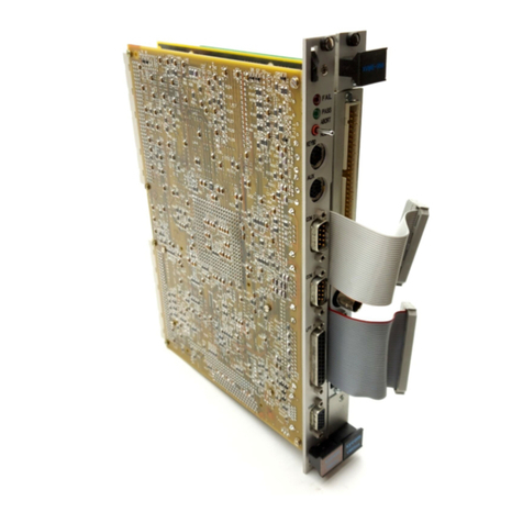
Xycom XVME-951 User manual

Artisan Technology Group is your source for quality
new and certied-used/pre-owned equipment
• FAST SHIPPING AND
DELIVERY
• TENS OF THOUSANDS OF
IN-STOCK ITEMS
• EQUIPMENT DEMOS
• HUNDREDS OF
MANUFACTURERS
SUPPORTED
• LEASING/MONTHLY
RENTALS
• ITAR CERTIFIED
SECURE ASSET SOLUTIONS
SERVICE CENTER REPAIRS
Experienced engineers and technicians on staff
at our full-service, in-house repair center
WE BUY USED EQUIPMENT
Sell your excess, underutilized, and idle used equipment
We also offer credit for buy-backs and trade-ins
www.artisantg.com/WeBuyEquipment
REMOTE INSPECTION
Remotely inspect equipment before purchasing with
our interactive website at www.instraview.com
LOOKING FOR MORE INFORMATION?
Visit us on the web at www.artisantg.com for more
information on price quotations, drivers, technical
specications, manuals, and documentation
Contact us: (888) 88-SOURCE | sales@artisantg.com | www.artisantg.com
SM
View
Instra

0
1994
XYCOM, INC.
Printed
in
the United States
of
America
Part
Number
74951-OOlC
XVME1951
PC/XT
VMEbus Adapter
Module Manual
74951
-001C
XYCOM
750
North
Maple Road
Saline,Michigan 48176
(313)
429-4971
Artisan Technology Group - Quality Instrumentation ... Guaranteed | (888) 88-SOURCE | www.artisantg.com

Artisan Technology Group - Quality Instrumentation ... Guaranteed | (888) 88-SOURCE | www.artisantg.com

XyColMREVISION
RECORD
I
Revision
IC
Description
Manual Released
Manual Updated
Manual Updated
Date
10/88
2/92
6/94
Trademark Information
Brand or product names are registered trademarks of their respective owners.
Copyright
In
formation
This document is copyrighted by Xycom Incorporated (Xycom) and shall not be reproduced or copied without
expressed written authorization from Xycom.
The information contained within this document is subject to change without notice. Xycom does not guarantee the
accuracy
of
the information and makes no commitment toward keeping it up to date.
Address comments concerning this
manual to:
xycom
Technical Publications Department
750
North
Maple Road
Saline, Michigan 48176
Part Number:
74951-001
C
Artisan Technology Group - Quality Instrumentation ... Guaranteed | (888) 88-SOURCE | www.artisantg.com

Artisan Technology Group - Quality Instrumentation ... Guaranteed | (888) 88-SOURCE | www.artisantg.com

TABLE OF CONTENTS
CHAPTER TITLE PAGE
1
INTRODUCTION
2
1.1 Product Overview
1.2 Manual Structure
1.3 Module Operational Description
1.4 Specifications
2.1
2.2
2.3
2.4
2.4.1
2.4.2
A
FIGURE
1-1
2-
1
2-2
2-3
2-4
TABLE
1-1
2-1
INSTALLATION
Introduction
Installing a Short Card
Installing Disk Drive Cables
Installing The Module
Installing an XVME-95111
Installing an XVME-951/2
APPENDICES
Block Diagram, Assembly Drawing, and Schematics
LIST OF
FIGURES
1-1
1-1
1-1
1-3
2-1
2-1
2-4
2-5
2-5
2-7
TITLE PAGE
Module Operational Block Diagram 1-2
XVME-951 with PC/XT Short Card
Installing the XVME-951/1/2 Disk Drive Cables
Installing the XVME-951/2 onto a CPU
2-1
2-4
2-8
XVME-957/12 2-10
Installing the XVME-951/2 onto an XVME-956/12 or
LIST
OF
TABLES
TITLE PAGE
Adapter Module Specifications
1.
-3
Jumper Signals
2-3
i
Artisan Technology Group - Quality Instrumentation ... Guaranteed | (888) 88-SOURCE | www.artisantg.com

Artisan Technology Group - Quality Instrumentation ... Guaranteed | (888) 88-SOURCE | www.artisantg.com

Chapter 1
-
INTRODUCTION
1.1
PRODUCT OVERVIEW
The XVME-951 PC/XT VMEbus Adapter Module is a double-high, double-wide VMEbus compatible
board that occupies two VMEbus card slots. The XVME-951 enables you to integrate your unique
PC/XT short cards, such as modem and communication modules, into your VME bus system. The
XVME-95111 is designed to operate with Xycom's XVME-684, XVME-686, or XVME-687 VMEbus
PC/AT processor modules. The XVME-951/2 is designed to operate with the XVME-674, XVME-677,
XVME-678, and XVME-688 VMEbus PUAT processor module.
1.2
MANUAL
STRUCTURE!
This manual introduces you to the general specifications and functional capabilities of the XVME-951
adapter module and provides instructions for its installation.
-
Briefly reviewing the outline of the manual structure should help direct you to the specific sections of
information relevant to your needs. The chapters are presented as follows:
Chapter
1:
Introduction
-
Provides a general description of the adapter module including functional
capabilities, buffer outputs, VMEbus compliance information, and a detailed block
diagram.
Chapter
2:
Installation
-
Details installation information about attaching the PC/XT short cards to
the module, installing the module in the chassis, and positioning the board interconnect
cable at the rear of the chassis.
Appendix A:
Block
Diagram, Assembly Drawing, and Schematics
1.3
MODULE OPERATIONALDESCRIPTION
Figure 1-1 on the following page shows an operational block diagram of the XVME-951 adapter module.
1-1
Artisan Technology Group - Quality Instrumentation ... Guaranteed | (888) 88-SOURCE | www.artisantg.com

Chapter
1
-
Introduction
I
I
I
I
I
I
I
I
I
I
I
I
I
I
I
I
I
I
I
I
I
I
I
I
I
I
I
I
I
I
I
I
I
I
I
I
I
I
I
I
I
I
I
I
I
I
I
I
I
I
I
I
I
I
I
I
I
I
I
I
I
I
I
I
I
I
I
I
I
I
I
I
I
I
I
I
I
I
I
I
I
I
I
I
I
I
I
I
I
I
I
I
I
I
I
I
I
I
I
I
I
I
I
I
I
I
I
I
I
BUFFERS
DATABUS
ADDRESS JUMPERS
&
CONTROL
BUFFERS
L----------
.--
.--__-________-___.
-_
7
PCMTBUS SIGNALS
XVME-95111: P2 ROWS
A
&
C
XVME-951Q: PXTl
PCMT
CARD
Figure
1-1,
Module Operational Block Diagram
1-2
Artisan Technology Group - Quality Instrumentation ... Guaranteed | (888) 88-SOURCE | www.artisantg.com

XVME-951
Manual
June
1994
1.4
SPECIFIC
ATIONS
Table
1-1
lists the various operational specifications for the XVME-951 adapter module.
Table 1-1. Adapter Module Specifications
Characteristic
Power Requirements (without PC/XT card
installed)
Buffer Outputs
Allowable PC/XT Card Dimensions
PC/XT Signals
VMEbus Compliance
Specification
+5V: 250
mA,
typical
450
mA,
maximum
VoL: .5V max. IoL: 64
mA
VoH: 2.0V min. IOH: -15
mA
Height: 4.0" max., 3.5" min.
Width:
5.70"
max.
Buffered:
SAO-SA19
SMEMR*, SMEMW*
IOW*, IOR*
DACKl",
2*
&
3*
T/C, BALE
REFRESH*
CLK
osc
RESETDRV
AEN
IRQ3-7, 9
DRQ1-3
Unbuffered:
SDO-7
I/O CH CK*
I/O CH RDY*
Double-high, double-wide VMEbus form factor
1-3
Artisan Technology Group - Quality Instrumentation ... Guaranteed | (888) 88-SOURCE | www.artisantg.com

Artisan Technology Group - Quality Instrumentation ... Guaranteed | (888) 88-SOURCE | www.artisantg.com

Chapter 2
-
INSTALLATION
2.1
INTRODUCTION
This chapter explains how to install the XVME-951 adapter module in three steps: attaching the PC/XT
card to the XVME-951 card, connecting the disk drive cables, and installing the entire module into the
VMEbus system. The first and second steps are the same for both versions
of
the XVME-95
1,
but the
third step depends on which version of the XVME-951 is being used.
2.2
INSTALLING
A
SHORT
CARD
Before you attach the PC/XT short card to the XVME-951 adaptor, refer to Figure 2-1 below.
Figure 2-1. XVME-951 with PC/XT
Short
Card
2-1
Artisan Technology Group - Quality Instrumentation ... Guaranteed | (888) 88-SOURCE | www.artisantg.com

Chapter
2
-
Installation
To attach a PC/XT short card to the XVME-951 module board, follow the instructions below:
1.
2.
3.
4.
5.
6.
7.
The adjustable card mounting bracket on the XVME-951 (located near the P2 connector) needs to
be removed from the module board before the PC/XT card can be attached. To detach the bracket,
simply remove both screws.
Hold the PC/XT card
so
that the side with the components on it faces up and the
ORB
is at the front
panel side of the module. The edge connector of the PC/XT card should now face the card edge
receptacle that is on the XVME-951. Slide the edge connector into the card edge receptacle until
fully engaged (only minimal pressure should be applied).
Center the protective mylar on the card mounting holes near the top edge of the PC/XT card. The
mylar should extend under the PC/XT card to prevent it from touching the XVME-951.
Snap the plastic edge of the card mounting bracket onto the top edge of the PC/XT card, keeping
the protective mylar centered beneath it.
NOTE
Never operate the XVME-951 without the protective mylar installed under
the card mounting bracket and PC/XT card. Operating the XVME-951
without the mylar may damage the XVME-951 and/or PC/XT card.
If necessary, slide the bracket and/or mylar in the needed direction to properly align the slots in the
bracket, the holes in the mylar, and the mounting holes in the XVME-951.
When the holes are properly aligned, tighten the two screws, lock washers, and nuts firmly,
so
that
the nuts are on the same side of the board as the card.
Slide down the adjustable
ORB
bracket on the front panel (located near the top of the XVME-951)
until it touches the PC/XT card
ORB.
Then tighten the two together with the nut and screw
provided.
2-2
Artisan Technology Group - Quality Instrumentation ... Guaranteed | (888) 88-SOURCE | www.artisantg.com

ME-951
Manual
June
1994
8.
Install the jumpers
on
the XVME-951 required by the PC/XT card installed. The IRQ signals and
DRQ signals are buffered from the PC/XT card and, through the jumpers, are driven to the CPU
module. Thesejumpers (shipped with the XVME-951) must be installed only if the corresponding
signal is needed by the PC/XT module and only if the corresponding signal does not conflict with
the CPU module. The jumpers are mapped to the signals as follows:
Table 2-1. Jumper Signals
All jumpers are out when shipped from the factory. Only install the ones needed by a particular
PUXT module installed on the XVME-95
1
module.
NOTE
J1
must
be installed for proper operation.
I
I
2-3
Artisan Technology Group - Quality Instrumentation ... Guaranteed | (888) 88-SOURCE | www.artisantg.com

Chapter
2
-
Installation
2.3
INSTALLING
DISK
DRIVE
CABLES
Both versions of the XVME-951 have holes in the PCB to facilitate routing cables for disk drive modules
such as the XVME-955. When using these drive modules, the XVME-951 resides between the CPU
module and the disk drive module. The cables, which connect the CPU module to the disk drive module,
route through these holes as illustrated in Figure 2-2.
If you are not using a disk drive module, go to the next section. Otherwise, follow the steps outlined
below:
1.
2.
3.
The cables shipped with the disk drive unit are not long enough to accommodate passage through
the XVME-951. The cables need
to
be 13 inches long. These longer cables need to be made or
may be ordered from Xycom.
Connect both cables to the CPU module in an orientation such that the cables route towards the P1
and
P2
connector
of
the CPU module.
Route the cables through the holes in the XVME-951's
PCB.
After passing through the holes, the
cables will route on the right side of the XVME-951 and connect to the disk drive module.
ROUTING
CABLES
COMPONENT
SIDE
r
I
Figure 2-2. Installing. the XVME-951/1/2 Disk Drive Cables
2-4
Artisan Technology Group - Quality Instrumentation ... Guaranteed | (888) 88-SOURCE | www.artisantg.com

ME-951
Manual
June
1994
2.4
INSTALLING THE MODULE
The XVME-951 comes in two versions: /1 and /2. The XVME-951/1 is used to interface with CPU
modules which connect the PCbus to the VME P2 connector (such as Xycom's XVME-684, 686, and
687). The XVME-951/2 is used
to
interface with CPU modules which connect the PCbus to the
interboard connector PXTl (such as Xycom's XVME-674, 677, 678, and 688). Refer to Section 2.4.1
for the XVME-951/1, or 2.4.2 for XVME-951/2.
2.4.1
Installing
an
XVME-951/1
To install an XVME-951/1 module:
1.
2.
3.
4.
5.
Install the CPU module and insure the two cardcage slots to the right of the CPU module are clear
and accessible. The XVME-951/1 module occupies two slots and needs to be placed to the right
of the CPU module.
Center the XVME-951/1 module on the plastic guides in the slots.
Push the module slowly to the rear of the chassis until the P1 and P2 connectors engage.
Apply straightforward pressure to the handles on the front panel until the connectors engage and are
properly seated.
Install the backplane connector
The backplane connector used
to
connect the CPU module's P2 connector(§) to the XVME-95111
module's P2 connector needs to be installed. The installationdepends on whether the CPU module
is comprised of two boards (XVME-684 and
687)
or one board (XVME-686).
Refer
to
Section 2.4.1.1 for instructions on installing a backplane connector for two board CPU
modules and to Section 2.4.1.2 for instructions on installing a backplane connector for the one board
CPU module.
2-5
Artisan Technology Group - Quality Instrumentation ... Guaranteed | (888) 88-SOURCE | www.artisantg.com

Chapter
2
-
Installation
2.4.1.1
TWO
Board CPU Modules
(XVME-684
and
XVME-687)
Two board CPU modules utilize a three position backplane (shipped with the CPU module) to connect
the boards’ P2 connectors.
To install into the backplane:
1. Remove the two position backplane if it
is
already installed. On the back side of the VMEbus P2
backplane, locate the three P2 connectors used by the CPU module and the XVME-951/1 module.
2. Install the three position backplane (shippedwith the XVME-951/1) into the three P2 connectors of
the P2 backplane. Make sure pin 1, clearly marked on the three position backplane, is oriented
towards the top.
2.4.1.2
One
Board CPU
Modules
(XVME-686)
The CPU module and the XVME-951/1 module will occupy three slots, but only connect to two
P2
connectors. (The right-most slot will be occupied by the XVME-951/1 but have no P2 connection.)
To install into the backplane:
1. Locate the P2 connectors which correspond to the three slots occupied by the CPU module and the
XVME-951 on the back side of the VMEbus P2 backplane.
2. Install the three position backplane (shipped with the XVME-951/1) into the three P2 connectors of
the P2 backplane. Make sure pin 1, clearly marked on the three position backplane, is oriented
towards the top.
2-6
Artisan Technology Group - Quality Instrumentation ... Guaranteed | (888) 88-SOURCE | www.artisantg.com

2.4.2
Installing
an
xVME-951/2
This section details the installation of an XVME-951/2 module to a CPU module or an XVME-956112
or XVME-957/12 module.
Before you start the installation:
1. The XVME-951/2 module occupies two slots and needs to be placed next to the CPU module.
Insure that the following cardcage slot(s) are clear and accessible:
slot(s) occupied by the CPU module
slots to the right of the CPU module (required by the XVME-95112)
2. Locate the bag containing the screws and standoffs which shipped with the XVME-951/2.
2.4.2.1
Installing
an
xVME-951/2Module
onto
a
CPU
Module
To install an XVME-951/2 module onto a CPU module:
1. Remove and discard the connector P2 screw and nut closest to the bottom corner of the CPU
module. Refer to Figure 2-3.
2. Attach the long female/female standoff to the solder side of the XVME-951/2 module, as illustrated
in Figure 2-3, using a short screw.
3.
Attach the short female/female standoff to the solder side of the XVME-951/2module, as illustrated
in Figure 2-3, using a short screw.
2-
7
Artisan Technology Group - Quality Instrumentation ... Guaranteed | (888) 88-SOURCE | www.artisantg.com

Chapter
2
-
Installation
STANDOFF
PXT
1
CONNECTOR
EXISTING
SCREW
AND NUT
XVME-951
'
4
COMPONENT
I/
SIDE
I
SCREW(4)
COMPONENT
/
SIDE
SCREW(4)
a-
'
I
\
'%
'I
\
'%
\
\
Figure 2-3. Installing the XVME-951/2 onto
a
CPU
4.
Align the pins of the XVME-951/2 module's PXTl connector with the CPU module's
PXTl
connector socket. Gently press the two modules together until the standoffs (mounted
on
the 951
module) touch the component side of the CPU module. Insure that the two holes
on
the CPU
module align with the standoffs.
5.
Insert two long screws through the solder side of the CPU module into the standoffs.
2-8
Artisan Technology Group - Quality Instrumentation ... Guaranteed | (888) 88-SOURCE | www.artisantg.com

mE-951
Manual
June
1994
6.
Center the boards of the CPU and XVME-951/2modules onthe plastic guides of the VME chassis.
7. Push the modules slowly to the rear of the chassis until the P1 and P2 connectors
of
the CPU
module engage.
8.
Apply straightforward pressure to the handles of the front panel of the CPU module until its
connectors engage and are properly seated.
Do
not apply pressure to the handles on the front panel
of the XVME-951/2 because there are no P1 and P2 connectors on the XVME-951/2.
2.4.2.3
Installing
an
XVME-951/2
Module
onto
an
XVME-956/12
or
956112
Module
To install an XVME-951/2 module onto an XVME-956/12 or 957/12 module:
1. Remove the two screws from the component side of the XVME-956/12 or the 957/12 module.
Refer to Figure 2-4.
2. Screwthe supplied male/female standoffs into the XVME-956/12 or 957/12, where the screws were
removed in Step 1. Refer to Figure 2-4.
3.
Align the
pins
of the XVME-951/2 module's PATl connector with the XVME-956/12 or XVME-
957/12 module's PATl connector socket. Gently press the modules together until the standoffs
(mounted on the 956 or 957 module) touch the solder side of the 951 module. Insure that the two
holes on the 951 module align with the standoffs.
4. Insert the two screws from Step 1through the component side of the XVME-95112 module into the
standoffs.
5.
Align the pins of the XVME-956/12 or 957/12 module's PATl connector with the CPU module's
PXTl and PATl connector socket. Then secure the 956/12 or 957/12 and 951/2 assembly to the
CPU module using long and short female/female standoffs and long screws supplied with the 956/12
or 957/12 module.
6.
Center the boards of the CPU, XVME-956/12 or 957/12, and XVME-951/2 modules on the plastic
guides of the VME chassis.
7. Push the modules slowly to the rear of the chassis until the P1 and P2 connectors of the CPU
module engage.
8.
Apply straightforward pressure to the handles
of
the front panel of the CPU module until its
connectors engage and are properly seated.
Do
not apply pressure to the handles on the front panels
of the XVME-956/12 or XVME-957/12 and XVME-951/2, because there are no P1 and P2
connectors on these modules.
2-9
Artisan Technology Group - Quality Instrumentation ... Guaranteed | (888) 88-SOURCE | www.artisantg.com
Table of contents
Other Xycom Control Unit manuals

Xycom
Xycom XVME-976 User manual

Xycom
Xycom XVME-976/202 User manual

Xycom
Xycom XVME-678 User manual

Xycom
Xycom XVME-977 User manual

Xycom
Xycom XVME-956 Series User manual

Xycom
Xycom XVME-653 User manual

Xycom
Xycom XVME-682 User manual

Xycom
Xycom XVME-678 User manual

Xycom
Xycom XVME-530 User manual

Xycom
Xycom XVME-100 User manual
Popular Control Unit manuals by other brands

Baker Hughes
Baker Hughes Mooney Flowgrid Slam Shut instruction manual

Meinberg
Meinberg IMS-MRI Setup guide

Exodraft
Exodraft EFC21 user guide

ON Semiconductor
ON Semiconductor EZAIRO 7160 SL Getting started guide

Warner
Warner CBC-300 Series Installation & operating instructions

Thyracont
Thyracont VD9 operating instructions