nVent RAYCHEM Elexant 5010i User manual

Elexant 5010i
Elexant 5010i-LIM
Installation Instructions

2
|
nVent.com/RAYCHEM
Figure 1: Tools/ Werkzeuge/ Outils/ Инструменты
*For 20 mm gland/ für 20 mm Verschraubung/ pour presse-étoupe 20 mm/ для 20-мм сальника
**For 20/25 adapter/ für 20/25 Adapter/ pour un adaptateur 20/25/ для переходника 20/25
3mm 7mm 25 mm* 36 mm**
A
220 120
120
Elexant 5010i-LIM
Connections / Anschlüsse / Raccordements / Подключения Connections / Anschlüsse / Raccordements / Подключения
Ex i Ex e
Heat-Tracing Temperature Control Unit with Safety Limiter
Temperaturregler mit Sicherheitstemperaturbegrenzer
Блок управления температурой системы электрообогрева
с ограничителем безопасности
nVent.com
©2023 RAYCHEM-LBL-EU2005-Elexant5010iLIMFront-ML-2301
Contrôleur/Limiteur de température pour traçage électrique
WARNING/WARNUNG/AVERTISSEMENT/ВНИМАНИЕ
NON-INTRINSICALLY SAFE CIRCUITS PROTECTED BY
INTERNAL IP30 COVER/ NICHT EIGENSICHERE ABGÄNGE
DURCH INTERNE IP30-ABDECKUNG GESCHÜTZT/
CIRCUITS À SÉCURITÉ NON INTRINSÈQUE PROTÉGÉS PAR
UN COUVERCLE INTERNE IP30/ НЕИСКРОБЕЗОПАСНЫЕ
ЦЕПИ ЗАЩИЩЕНЫ ВНУТРЕННЕЙ КРЫШКОЙ C IP30
Figure 2: Dimensions/ Abmessungen/ Dimensions Elexant 5010i(-LIM)
B

nVent.com/RAYCHEM
|
3
When the device is the last on the
communication wire, install a wire bridge
between the “-” and “T” terminal as
shown by the straight line4
RTD Lim RS-485
RS-485
Internal End Of
line resistor3Alarm
3A Max
heater6
PT100 temperature sensor(s)5
W R R PE
S + –
S T+ –
Li Lo Ni No PE PE PE Lo No
W R R PE
W R R PE
RTD 2
RTD 1
RS-485 cable coming
from previous device1
RS-485 cable going to
next device2
PE
N
L
PE
N
L
PE
Figure 3: connection diagram/ Anschlussplan/ Schéma de connexion/ Схема подключения Elexant 5010i
C
1RS-485-Kabel vom vorherigen Gerät/ Câble RS-485 de l'appareil précédent/ Кабель RS-485 от предыдущего устройства
2RS-485-Kabel zum nächsten Gerät/ Câble RS-485 vers appareil suivant/ Кабель RS-485 к следующему устройству
3Internes RS-485-Ende mit Leitungsab-schlusswiderstand/ Résistance interne RS-485 d'extrémité de ligne / Внутренний конец
оконечного сопротивления RS-485
4Wenn es sich bei dem Gerät um das letzte innerhalb eines Bussystems handelt, muss eine Drahtbrücke zwischen Anschluss „-" und
„T" vorgesehen werden (siehe gestrichelte Linie)/ Lorsque l'appareil est le dernier de la ligne de communication, installez un câble
de pontage entre les bornes "-" et "T" comme indiqué par la ligne pointillée/ В случае, если устройство является последним в
цепочке,необходимо установить перемычку между клеммами « -» и «Т» (показана пунктиром)
5Temperaturfühler PT100/ Sonde(s) de température PT100/ Датчик(и) температуры PT100
6 Heizleitung/ Câble chauffant/ Греющий кабель

4
|
nVent.com/RAYCHEM
Elexant i & Elexant i LIM
UL 22 ATEX 2446X
II 2G Ex eb ib mb [ib] IIC T4Gb
II 2D Ex tb [ib] IIIC T67°C Db IP66
–50°C ≤Tamb ≤+60°C
IECEx UL 22.0034X Ex eb ib mb [ib] IIC T4Gb
Ex tb [ib] IIIC T67°C Db IP66
Functional safety approval* (Elexant i)
CSA FSP 21016
SIL 2(1oo1)
* Funktionssicherheitszulassung/ Agrément sécurité fonctionnelle/ Сертификация для функциональной безопасности

nVent.com/RAYCHEM
|
5
ENGLISH
Warning:
The purchaser should make the manufacturer aware of any external effects or aggressive substances that the equipment may be
exposed to.
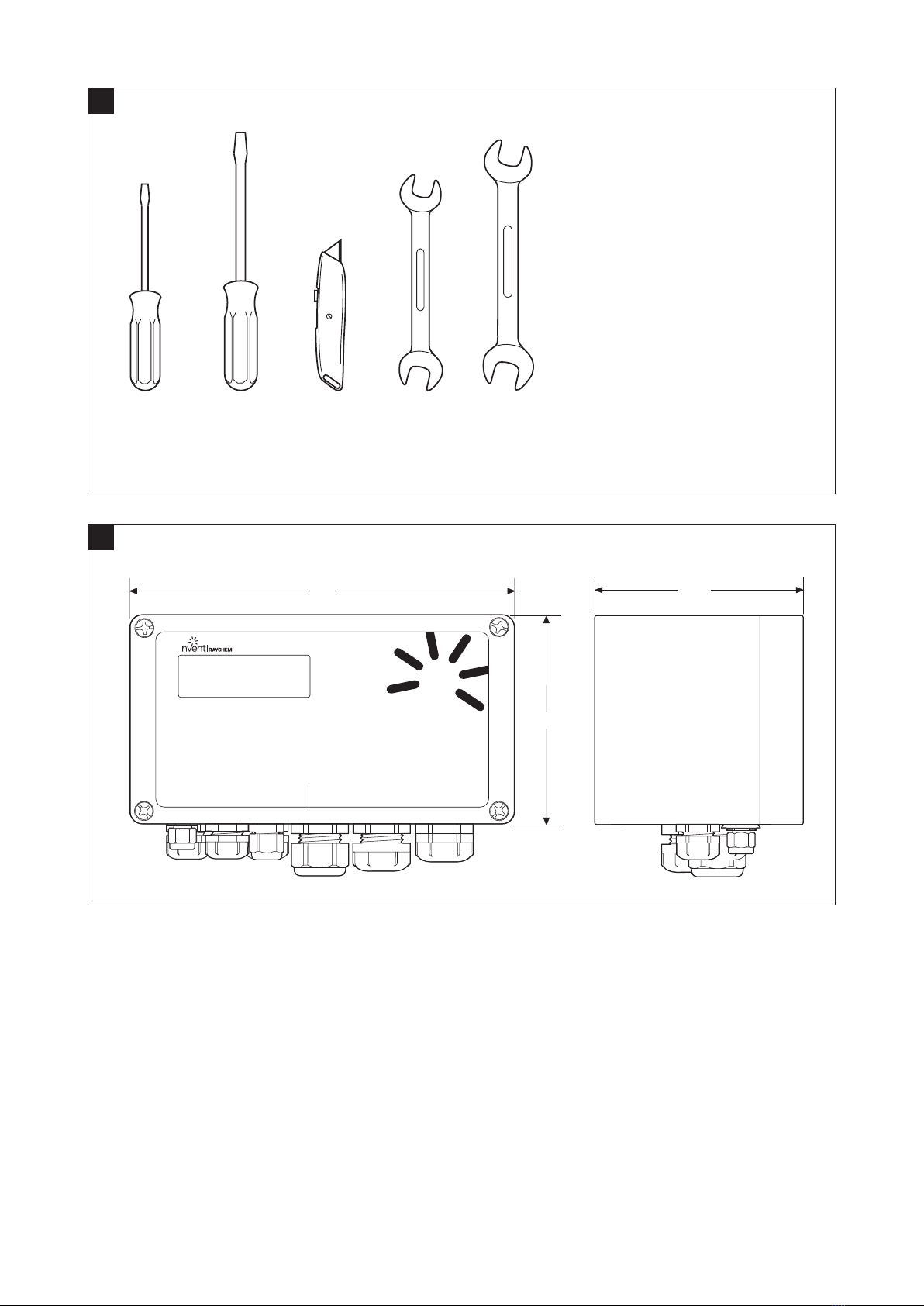
The cable glands shall only be used for fixed installations, the cables must be fixed to prevent pulling or twisting.
Important Notice: In case a failure of the safety system is detected either during operation or during routine maintenance when
executing a function test the unit should be switched off and taken out of service. Defects in the safety system cannot be repaired
in the field. Defective units are to be replaced and returned to the manufacturer for investigation. Please contact your nearest nVent
representative for more instructions. A list of worldwide representations can be found on the last page of this document or on
nVent.com/RAYCHEM
Please read all instructional literature carefully and thoroughly before starting.
Notice: The information contained in this document is subject to change without notice. Please read these Installation Instructions
before commissioning the instrument. Keep the instructions in a place which is always accessible to all users. Please assist us to
improve these instructions, where necessary. We are always grateful for your suggestions. Should any difficulties arise during
start-up, you are asked not to carry out any unauthorized manipulations on the instrument as this could affect your warranty rights!
Please contact the nearest nVent subsidiary or the head office. If any servicing is required, the instrument must be returned to the head
office.
Special conditions for safe use
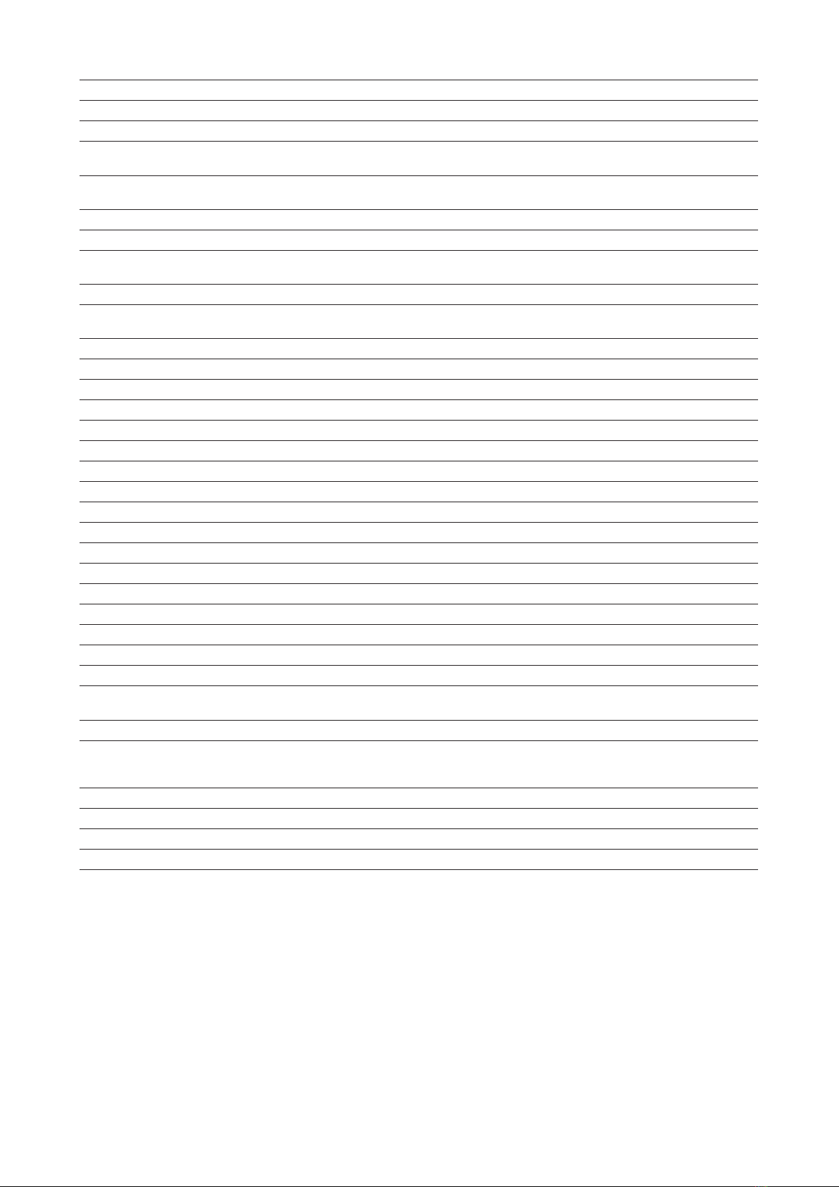
• Cable entry shall be Ex eb and tb ATEX certified and rated minimum IP66 to maintain the IP66 rating of the enclosure. Cable entry
devices must have a seal or gasket to provide sealing with the enclosure.
• Unused cable entries must be filled with Ex eb and tb ATEX certified and rated minimum IP66 stopping plugs to maintain the IP66
rating of the enclosure. Cable entry plugs must have a seal or gasket to provide sealing with enclosure.
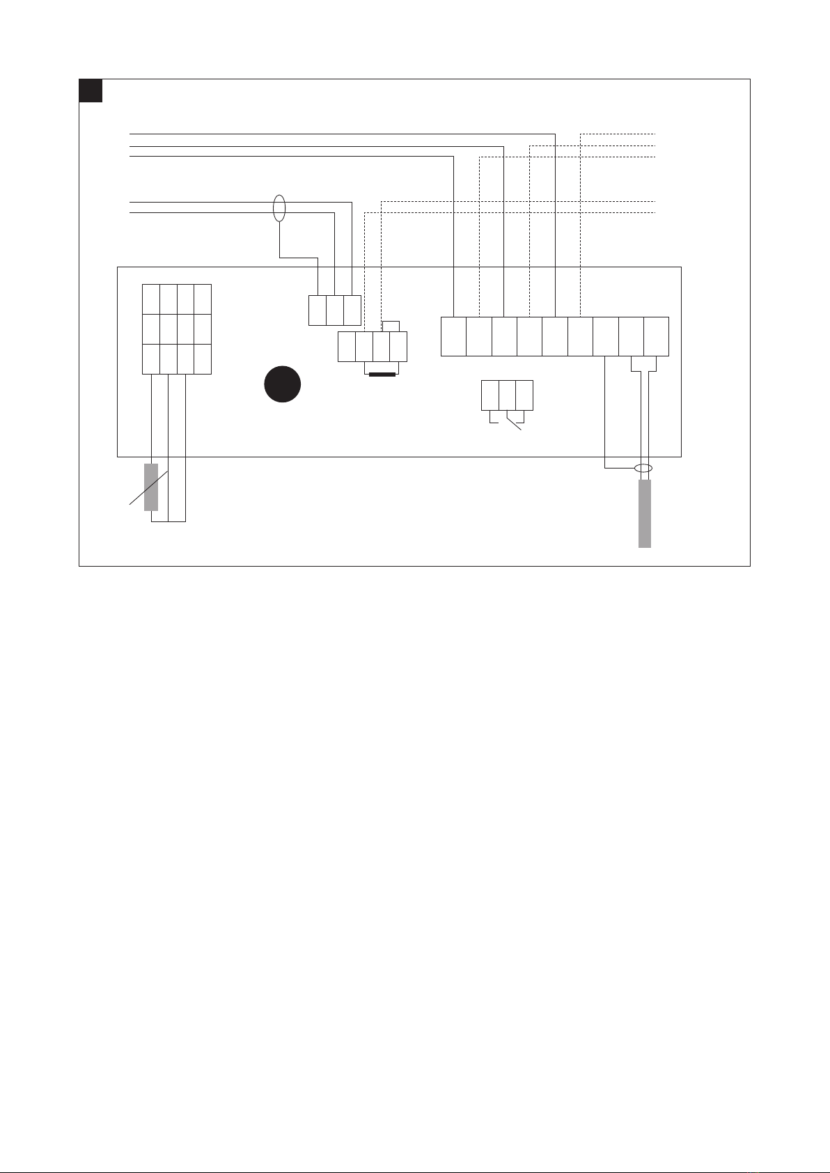
• Not more than one single or multiple strand wiring lead shall be connected into either side of the terminals.
• Leads connected to the terminals shall be insulated for the appropriate voltage and this insulation shall extend to within 1 mm of the
metal of the terminal throat.
• The maximum permitted current of the non-IS alarm contacts is 3 A.
• The earth pillar adjacent to the RTD connectors must be used only for RTD cable screens.
• The external RTDs must be capable of withstanding a 500 V test to earth.
Certification
nVent certifies that this product met its published specifications at the time of shipment from the factory.
Warranty
This nVent product is warranted against defects in material and workmanship for a period of 12 months from the date of installation
or 30 months maximum from the date of shipment, whichever occurs first. During the warranty period, nVent will, at its option, either
repair or replace products that prove to be defective. For warranty service or repair, this product must be returned to a service facility
designated by nVent. The Buyer shall prepay shipping charges to nVent and nVent shall pay shipping charges to return the product to the
Buyer. However, the Buyer shall pay all shipping charges, duties, and taxes for products returned to nVent from another country. nVent
warrants that the software and firmware designated by nVent for use with a product will execute its programming instructions properly
when installed on that product. nVent does not warrant that the operation of the hardware, or software, or firmware will be uninterrupted
or error-free.
Limitation of warranty
The foregoing warranty shall not apply to defects resulting from improper or inadequate maintenance by the Buyer, Buyer-supplied
software or interfacing, unauthorized modification or misuse, operation outside of the specifications for the product, or improper
installation.
NO OTHER WARRANTY IS EXPRESSED OR IMPLIED. NVENT DISCLAIMS THE IMPLIED WARRANTIES OF MERCHANTABILITY AND
FITNESS FOR A PARTICULAR PURPOSE.
Exclusive remedies
THE REMEDIES PROVIDED HEREIN ARE THE BUYER’S SOLE AND EXCLUSIVE REMEDIES. NVENT SHALL NOT BE LIABLE FOR ANY
DIRECT, INDIRECT, SPECIAL, INCIDENTAL, OR CONSEQUENTIAL DAMAGES, WHETHER BASED ON CONTRACT, TORT, OR ANY OTHER
LEGAL THEORY.
Statement of compliance
This equipment has been tested and found to comply with the low voltage directive 2014/35/EU, the ATEX directive 2014/34/EU and
the electromagnetic compatibility directive 2014/30/EU. These limits are defined to provide reasonable protection against harmful
interference in a residential installation (technical data mentions industrial application). This equipment generates, uses and can
radiate radio frequency energy and, if not installed and used in accordance with the instructions, may cause harmful interference to
radio communications. However, there is no guarantee that interference will not occur in a particular installation. If this equipment does
cause harmful interference to radio or television reception, which can be determined by turning the equipment off and on, the user is
encouraged to try to correct the interference by one or more of the following measures:

6
|
nVent.com/RAYCHEM
• Reorientate or relocate the receiving antenna.
• Increase the separation between the equipment and receiver.
• Connect the equipment into an outlet on a circuit different from that to which the receiver is connected.
• Consult the dealer or an experienced radio/TV technician for help.
Area of use
nVent RAYCHEM 5010i-(LIM) controllers are used for temperature control and temperature limiting of electrical heaters in industrial and
potentially explosive atmospheres. The Elexant 5010i-(LIM) consists of a temperature controller and an additional safety temperature
limiter. Elexant 5010i-(LIM) units are approved for use in hazardous area Zone 1and Zone 2(Gas) and Zone 21 and Zone 22 (Dust).
Where needed, the temperature sensor of the unit can be placed in Zone 0(Zone 20) However, the control unit itself is not approved for
being installed in Zone 0(Zone 20).
Safety instructions
During operation, do not leave this Installation Manual or other objects inside the enclosure. Use the temperature controller and limiter
only for its intended purpose and operate it only in clean, undamaged condition. In the event of incorrect assembly, the requirements of
IP66 as specified by IEC 60529:2001 are no longer met. Do not make any modifications to the temperature controller and limiter that are
not expressly mentioned in this Installation Manual. Whenever work is done on the temperature controller and limiter, be sure to observe
the national safety and accident prevention regulations and the safety instructions given in this Installation Manual.
Technical data
Application type
Elexant 5010i(-LIM) units are approved for use in Hazardous area Zone 1or Zone 2(Gas) or
Zone 21 or Zone 22 (Dust) and non-hazardous areas.
All values as per hazardous area certification. Current ratings are given for a supply voltage
range of 100 to 250Vac +/–10%, 25A, 47-63 Hz and resistive loads only.
Functional safety approval Sira FSP 21016 SIL 2IEC 61508-2:2010
Environmental
Ambient operating temperature From –50°C to +60°C
Storage temperature From –55°C to +80°C
Enclosure
Protection IP66 to IEC 60529
Material Glass fiber reinforced polyester with internal earth metallic plate on the bottom
Installation position Any position allowed, typical use with glands facing down
Threaded entries
3x M25:
1x M25 Gland Ø 8– 17 mm: Power IN/heating cable out
1x M25 Stopping plug: Daisy chaining of power
1x M25 Rain plug: Heating cable out
3x M20 Digital communication IN/OUT and alarm (all with stopping plugs)
2X M16 Temperature sensor(s) 1with stopping plug one with rain plug
Electrical data
Entity parameters for intrinsic
safe connections
Entity parameters for RTD 1, RTD 2, or RTD LIMITER per channel
Uo = 5,88V, Io = 0.0890A, Po = 0.131W, Co = 42.7μF, Lo = 4480μH.
Intrinsically safe specifications Um = 250 V
Power supply &
own power consumption
100 to 250 Vac +/–10% 47-63 Hz.
20 VA max.
Connection terminals All cage clamp style connection terminals:
L, N and PE terminals 9pc (0.2to 6mm²)
Alarm output terminals 3pc (0.2to 2.5mm²)
PT100 (RTD) terminals 8pc Elexant 5010i, 12 pc Elexant 5010i-LIM (cables with cross section ranging from
0.2to 1.5mm2)
RS-485 communication 7pc (0.2to 1.5mm²)
Internal earth stud 1pc (Max 6mm²)
Alarm output relay Contact rated 250 Vac 3A programmable to open, close or to toggle in case of alarm
Electrical safety EN 61010-1, Category III, Pollution degree 2.
Temperature sensors
Type 100 Ω platinum, 3-wire, α = 0.00385 Ω/°C. Can be extended with a three-core shielded or
braided cable of maximum 20 Ω lead resistance per conductor.
Quantity Two RTD inputs for the controller plus one independent temperature input for the limiter.
All temperature sensors are permanently monitored for “sensor open” and “sensor break”.

nVent.com/RAYCHEM
|
7
Communications
Physical network RS-485 and Class 1Bluetooth
Protocol / topology Modbus RTU or ASCII. Multi drop/Daisy Chain
Cable and maximum length Shielded twisted pair cable, 0.5mm² (AWG 24) or larger. Total cable length from first till last
device shall not be more than 1200 m.
Maximum quantity of controllers in
one network Max. 247 devices per field communication network
(Modbus) Network address Software configurable via nVent RAYCHEM Android tablet application
Configuration and setting
Method Through handheld programming device or via nVent
RAYCHEM Supervisor software/User Interface (TOUCH 1500, NGC-UIT)
Units of measure °C or °F, software selectable
Memory Nonvolatile. There is no loss of parameters after the event of power outage or long term shut
down. Data holding time ~10 years.
LED indicators Status LEDS are available for:
Elexant 5010i Heater, Alarm, RS-485 communication, Bluetooth communication.
Elexant 5010i-LIM Heater, Alarm, Limiter (tripped), RS-485 communication and Bluetooth.
Measuring ranges
Temperature range controller From –200°C to +700°C in steps of 1K
Temperature range limiter From +50°C to +599°C in steps of 1K (Elexant 5010i-LIM only)
Voltage From 90 Vac to 305 Vac
Load current From 0.1A to 25 A
Ground fault current From 10 mA to 500 mA (RCD/ELCB required due to IEC and/or local regulations).
Heater time alarm From 1to 1x 10⁶hours
Relay cycle alarm From 0to 2x 10⁶operations
Ordering information
Product name Part number EAN number
Elexant 5010i 2000002132 5414506023138
Elexant 5010i-LIM 2000002133 5414506023145
Elexant 5010i (EAC) 2000002370 5414506023152
Elexant 5010i-LIM (EAC) 2000002369 5414506023169
Elexant i accessories
Temperature sensors
Product name
MONI-PT100-260/2
MONI-PT100-EXE
MONI-PT100-EXE-SENSOR
Support bracket for installation on pipe
Product name SB-125
Bluetooth enabled handheld programming device with customized software
See for more information Android tablet TAB-Ex datasheet and Elexant Connect operations manual

8
|
nVent.com/RAYCHEM
1. INSTALLATION
For installation/operation, always observe the Equipment Safety Law, the rules of generally accepted engineering practice
(IEC60079-14/EN 60079-14), and the instructions stated in this Manual. Carry out work on the thermostats in the de-energized state only.
Mechanical installation
Elexant 5010i-LIM units comprise a temperature controller and a safety temperature limiter installed in one enclosure. The controllers
can be installed in any position on a stable structure by means of the 4mounting holes. Up to a pipe temperature of 210°C the
Elexant 5010i and Elexant 5010i-LIM units can be mounted directly on the pipe by means of a support bracket type SB-125. Ensure that
the ambient temperature of the equipment does not exceed 60°C at any time. In order to provide enough stability, the support bracket
shall be attached by means of 2pipe straps.
Elexant 5010i
Connections / Anschlüsse / Raccordements / Подключения
Ex i
Ex e
Heat-TracingTemperatureControl Unit
TemperaturreglerfürBegleitheizung
Блокуправления температуройсистемы электрообогрева
Contrôleurde Températurepour Traçage Electrique
nVent.com
©2022 RAYCHEM-LBL-EU2003-Elexant5010iFront-ML-2206
Elexant 5010i
Connections / Anschlüsse / Raccordements / Подключения
Ex i
Ex e
Heat-TracingTemperature Control Unit
Temperaturreglerfür Begleitheizung
Блокуправления температурой системы электрообогрева
ContrôleurdeTempérature pour Traçage Electrique
nVent.com
©2022 RAYCHEM-LBL-EU2003-Elexant5010iFront-ML-2206
Figure 4: Mounting positions Elexant 5010i(-LIM)
Connecting cables and cable glands to Elexant i and Elexant i-LIM units.
Installation instructions for glands (threaded holes only)
At ambient temperatures > 45 °C the selected cable should have a temperature rating of 80°C or higher. Cable glands with a
temperature rating of 80°C or higher should be selected.
2xM16x1.5
3xM20x1.5
3xM25x1.5
Figure 5
Tolerance class Tolerance class for Ex e glands is maximum 6G/6H.
Enclosure material limitations
When plastic glands are used, only plastic glands made from flame retardant, high
impact resistant polyamide shall be used. The glands shall be suitably certified for the
intended area of use.
Maximum surface roughness of the
enclosure wall
Better than 3,2µm is recommended.
Maximum level of surface roughness allowed is Ra 6µm;

nVent.com/RAYCHEM
|
9
Enclosure interface sealing method If the sealing surfaces are uneven, use PTFE washer NFWM25 Or the green fiber
washer GFWM25 (Washers are to be ordered separately).
Thickness range for the enclosure wall (t) ≥ 4 mm
Perpendicularity +/–1° or 0.2mm at the outer edge of the gland, whichever is smaller.
Permitted use and location of any earth tags
For metal glands use an internal lock not to assure earth continuity via the
Elexant 5010i/Elexant 5010i-LIM internal earth plate. Alternatively, earth tags
connected to one of the internal PE terminals can be used.
For chamfered holes Only parallel threads are allowed.
Lock nuts Only use nVent RAYCHEM locknuts or types recommended by the gland
manufacturer.
Recommended torque values The installation instructions provided by the gland manufacturers must be followed.
Grounding and bonding (earthing)
Elexant 5010i/Elexant 5010i-LIM units must be earthed in accordance with the local wiring regulations. The Elexant 5010i/Elexant 5010i-LIM
earthing system is providing internal and external earth connection facilities. All internal and external parts of the Elexant 5010i/
Elexant 5010i-LIM earthing system are interconnected inside the encapsulant. When using the external earth stud the following
requirements apply for connection.
Outside Enclosure Wall
1
534324
τ
= 4,5 Nm
1. M6threaded earth stud (Greased, 1pc)
2. Serrated washer (1pc)
3. Washer (3pc)
4. M6threaded nut (Tightening Torque 4,5Nm) (2pc)
5. Seal Nyltite-Siegel (1pc)
Figure 6
Temperature sensors
The Elexant 5010i/Elexant 5010i-LIM temperature inputs are designed as intrinsically safe circuits (IEC 60079-11/EN60079-11 Ex [ib])
therefore any type of three wire DIN IEC 751 Class B PT100 resistance temperature devices can be used. The Elexant 5010i-LIM supports
3local temperature inputs, where 2are allocated to the temperature controller (RTD 1and RTD 2). The third temperature input is
reserved for the temperature limiter (RTD limiter). Elexant 5010i units on the other hand do not support the third input (RTD limiter).
Lead compensation of RTD connections
Elexant 5010i and Elexant 5010i-LIM units can provide up to 20 Ohm lead resistance compensation. This implies that sensor
connections may be extended using a three-core shielded or braided cable with a maximum length of up to 150 meters.
(max. 3x 1.5mm²) The screen or braid of the extension cable is to be grounded at the controllers end only.
Installation of temperature sensors
The temperature sensors must be installed in such a way that the sensor(s) measure(s) the surface temperature as reliably as possible.
Therefore, the guidelines as described in section 2.3.2.1need to be followed.
Temperature sensor of the temperature controller
Important guidelines on sensor positioning and installation:
• The correct position is on top of the pipe. (Figure 7)
• The sensor needs to be attached with sufficient glass tape (GT-66 or GS-54).
• Use two bands of glass tape to ensure its position. (Figure 7)
• The lead wire needs to leave the insulation so that no moisture can enter the cladding-insulation system. (Figure 8)
• Fix the sensor lead wire to prevent accidental strain on the sensor tip, which could alter its position.

10
|
nVent.com/RAYCHEM
Warning:
• Do not install sensor at ambient temperatures below –20°C. Do not bend sensor (last 50 mm), keep it straight under all
circumstances.
• To prevent damage to the sensor, no metal straps may be used, the use of fiberglass self-sticking tapes is recommended.
Figure 7: Mounting temperature sensing on pipe Figure 8: Sensor and lead entrance
Limiter temperature sensor on the pipe surface
The first method consists of using the surface temperature of the pipe as reference and preventing powering the heating cable when
the pipe temperature is above a calculated value. This value is dependent on the make of the cable and the design of the heating circuit.
Use TraceCalc Pro to determine this value and document the calculation in your filing.
The sensor is installed identical to the normal temperature sensor, at the top of the pipe, firmly attached to the surface by means of
glass tape. Special attention needs to be taken that the sensor lead does not cool the pipe/sensor; nor that moisture could enter the
insulation, cooling the sensor tip or reducing the insulation capacity in this area.
Limiter temperature sensor on an artificial HOT-SPOT
The second way of surface temperature limiting is to create an artificial hot spot. In order to guarantee the limiter sensor measures the
highest possible temperature of the installation, the temperature sensor of the limiter shall be installed on an artificial hotspot.
Figure 9: Artificial hot spot
Important guidelines on sensor positioning and installation:
• The correct position is on top of the pipe. See Figure 9.
• Fix the insulation pad with sufficient glass tape. (GT-66 or GS-54)
• Guide the heater from the bottom of the pipe to the insulation pad and fix it well so that it keeps its position.
• The sensor needs to be attached with sufficient glass tape to the heater. Use two bands of glass tape to ensure its position.
• The lead wire needs to leave the insulation so that no moisture can enter the cladding-insulation system. Fix the lead wire to the pipe
with glass tape if needed to ensure the stability of the hot spot system.
• Make sure that the nominal insulation thickness is respected over the hot spot, it might be necessary to use oversized insulation
shells.
Limiter temperature setting
• The limiter value (Tlim) needs to be set at the maximum allowed surface temperature (Tmax) minus 10 K when Tmax > 200°C.
• The limiter value (Tlim) needs to be set at the maximum allowed surface temperature (Tmax) minus 5 K when Tmax < 200°C.
Electrical installation
See page 3for electrical connection diagram of the Elexant 5010i controller. The limiter temperature sensor connection is only
applicable with the Elexant 5010i-LIM. The optional second PT100 temperature sensor for the control unit is omitted for clarity.
Communication and networking
The Elexant 5010i controller is equipped with a RS-485 interface. Through this interface up to 247 Elexant 5010i units can be networked
to a NGC-UIT/TOUCH 1500 or to one serial port of standard PC running Windows based Supervisor software.
Sensor
Pipe
Lead entrance
No No

nVent.com/RAYCHEM
|
11
Configuration
The Elexant 5010i controllers can be configured locally by means of a handheld programming device or from a central location using the
NGC-UIT/TOUCH 1500 or Supervisor Software. After programming, all settings are permanently stored in the nonvolatile memory of the
Elexant 5010i control unit, avoiding loss of data in the event of power failure or after a long-term power shutdown.
2. MAINTENANCE
Equipment placed into hazardous areas needs to comply with IEC/EN 60079-17 regarding inspection and maintenance requirements.
The IEC/EN 60079-17 describes in more detail the requirements regarding documentation, qualifications of personnel, inspections,
regular periodic inspections, continuous supervision by skilled persons, maintenance, isolation of apparatus, earthing and inspection
schedules.
3. SAFETY TEMPERATURE LIMITER
Safety limiter
The safety limiter option (-LIM option of the Elexant 5010i, see Table 1- Elexant 5010i Variants) provides a redundant high temperature
cut-out mechanism, suitable for use in safety critical applications. It disconnects power from the heater, preventing the system from
exceeding a safe temperature level.
Safety function of the limiter in the Elexant i-LIM
The safety function is invoked when the temperature limit is reached, or in the event of a fault (such as sensor break, sensor short-
circuit, component failure, or supply failure) even when the process conditions are within the permissible temperature range. The safety
function disconnects power to the attached equipment without delay.
Power may be restored to the attached equipment by manually resetting the safety function after the temperature returns below the
permissible limit, and no fault is present. The safety function may be reset using the RESET button on the front of the unit, or through
supervisory software connected via the communication ports or via handheld android device over Bluetooth.
In specific circumstances where there is no current flowing through the heat trace during the over-temperature event, the limiter will
self-reset once the temperature returns below the permissible limit and no fault is present.
Area of use
Safety limiters are used in areas where thermal processes need to be prevented from overheating, and where the system must be set to
a safe operating condition in the event of a fault. A typical example of such an installation is surface heating in a hazardous area.
Resetting the safety limiter
The safety limiter is designed such that after it has tripped, resetting it is possible only after the normal, safe operating conditions are
returned. If there was no current flowing through the heat trace at the time of the over-temperature condition, the safety limiter will reset
itself without user intervention. If there was current present in the heat trace during the over-temperature condition, then the device
needs to be manually reset.
In order to manually reset the limiter after it has tripped, the user needs to press the RESET button, under the lid of the Elexant 5010i
enclosure (shown in the Figure below). Alternatively, the limiter can be reset remotely using Supervisor software, Android tablet, or other
supervisory software. Refer to the operating manual for the supervisory software for detailed instructions on how to remotely reset a
safety limiter.
HEATER
ALARM
LIMITER
RS485
BLUETOOTH
RESET
LIMITER
SET
nVent RAYCHEM Elexant 5010i-LIM
Limiter reset button (rearm the limiter after it has tripped)
Limiter temperature set button to be pressed after
the polling process has been initiated
WARNING - Do not remove the cover
while energized
Figure 10: Elexant 5010i-LIM Front Panel with IP30 cover installed

12
|
nVent.com/RAYCHEM
Setting the limiter temperature set point
Choosing a set point
The lock out temperature (set point) of the safety limiter must be set in such a way that the maximum allowable temperature of the
equipment is not exceeded. For example, the surface temperature of a heat-tracing cable in a hazardous area cannot exceed the local
maximum temperature allowed based on the classification rating (T-rating) of the area. The set point should be the maximum allowed
temperature less 5°K for temperatures below or 200°C, or less 10°K for temperatures greater than 200°C.
Configuring the limiter set point
Modifying the set point requires physical access to the Elexant 5010i device. The lock out set point may be configured with any
supervisory software that allows the user to be physically close to the 5010i device. The procedure to modify the limiter set point is the
same for all user interfaces. Use your preferred configuration method to enter the set point and then press the SET button on the
Elexant 5010i device to confirm the set point change.
The SET button can be accessed by unscrewing and removing the top cover. The button must be pressed within 30 seconds after the
new setpoint has been entered. If the button is not pressed before this time interval has elapsed, the new value is discarded and the old
set point value remains unchanged. Once the new set point has been saved, it can be confirmed by holding the SET button, and reading
the setpoint (in °C) off the LED display.
Main output interlock
When the safety limiter output is off, for any reason, an internal signal overrides the output of the main output switch, to force it off.
The main output can only be switched on if the limiter temperature sensor is connected, and the measured temperature is below the
limiter set point. There is no user action required for this feature, and it cannot be disabled.
Internal diagnostic
The internal power to the limiter circuit is continually monitored by the limiter microprocessor. Any detected instability is reported to the
user via a status flag on the user interfaces. There is no known effect on the safety function in the presence of a detected power failure.
As a precaution, if the limiter power failure flag is persistent or recurring regularly, follow the instructions in Section 3.1.13– Response to
Fault Conditions.
Functional test
The Elexant 5010i Safety Limiter units meet the requirements of SIL2(see Section 3.1.11 PFDavg Safety Function for more details)
as set out in IEC61508:2010. In accordance with this standard, units are subjected to a functional test after commissioning and at
regular intervals, in order to guarantee safe and reliable operation. The test interval for the safety limiter can be set to 1, 10 or 20 years,
depending on the application. The functional test procedure is described in Section 3.1.8– Functional Test Procedure. Conformance to
the SIL certification is limited to the 20-year lifetime of the unit.
Type Safety Integrity Level Systematic Capability Proof Check Interval Unit Lifetime
5010i-Mod-IS-LIM SIL 2SC 2 1, 10, or 20 years 20 years
Table 2- Functional Test
Functional test procedure
The functional test is performed after commissioning and at regular intervals over its operational lifetime, to ensure it is still capable
of carrying out its intended safety function. This check requires a voltmeter capable of reading the output heater voltage, and a short
length of wire (5cm/2in).
Setup the functional test using these steps:
1. Reset any limiter-related trips.
2. Clear all alarms.
3. Ensure the controller output (and the HEATER LED) are on. The Control Mode can be switched to “Force ON” if required.
4. Setup check: Measure the voltage to the heater at the output terminals Lo and No, to verify the output is ON.
Execute the functional test by performing the following steps:
1. Disconnect one of the limiter RTD leads (sensors).
2. Result: The ALARM and LIMITER LEDs light up, and the HEATER LED switches off.
3. Check for OFF: Measure the voltage to the heater at the output terminals Lo and No, to verify the output is off.
4. Reconnect the limiter RTD (sensor). Wait about 10 seconds for the temperature reading to return on local display.
5. Press the RESET button.
6. Clear all alarms.
7. The HEATER LED is now on, the ALARM and LIMITER LEDs are off.
8. Check for ON: Measure the voltage to the heater at the output terminal, to verify the output is on.
9. Install a wire bridge between the W/B and rightmost R positions to simulate a short across the limiter RTD (sensor). Wait about 10
seconds for the short to be detected.
10.Result: The ALARM and LIMITER LEDs light up and the HEATER LED switches off.

nVent.com/RAYCHEM
|
13
11.Check for OFF: Measure the voltage to the heater at output terminals Lo and No, to verify the output is off.
12.Remove the wire bridge. Wait for 10 seconds for the temperature reading to return.
13.Press the RESET button.
14.Clear the alarms.
15.The HEATER LED is now on, and the ALARM and LIMITER LEDs are off.
16.Check for ON: Measure the voltage to the heater at output terminals Lo and No, to verify the output is on.
Clean up steps:
1. Return the control algorithm to its previous setting if it was changed to force the output on.
Test in the event of a fault
In the event of a system fault, the device is designed to fail safe whenever possible. If the limiter output does not close, even after
pressing the RESET button, check the Status of the Safety Limiter, and any active alarms in the supervisory software. If no issues
are indicated in these locations, or the error cannot be resolved by the installer, the unit may need to be replaced. See last page of
installation manual for contact information.
Determining safety integrity of the Elexant i-LIM
The Elexant 5010i-LIM is a Type B system, as defined in IEC61508-2:2010. A sub-system is a Type B system when all of the following
apply:
1. The failure mode of at least one component that is used is not adequately defined.
2. The response of the sub-system in fault conditions cannot be completely determined.
3. No adequately reliable failure data, based on field experience is available for the subsystem, to support the assumed failure rates for
recognized and unrecognized hazardous failures.
The Elexant 5010i Limiter variant meets the requirements for Systematic Capability (SC) 2. The following table presents the achievable
Safety Integrity Level (SIL), depending on the Safe Failure Fraction (SFF) and the Hardware Fault Tolerance (HFT) for Type B safety-
related subsystems. The table below is valid for the Elexant 5010i-LIM:
SFF of an element Hardware Fault Tolerance
0 1 2
< 60% Not Allowed SIL 1SIL 2
60% - 90% SIL 1SIL 2SIL 3
90% - 99% SIL 2SIL 3SIL 3
≥ 99% SIL 3SIL 3SIL 3
Table 3- Maximum SIL for Type B with SC 2
The Elexant 5010i-LIM is at HFT of 0, SIL2(90% - 99%) for Type B safety-related subsystems.
PFDavg safety function
The limiter temperature sensor and limiter electronics together form the safety related system that performs the safety function.
The “average probability of the hazardous failure of a safety function for the entire safety related system” (PFDavg) is divided among
the subsystems. An external device such as the temperature sensor, is specific to the installation, and shall in accordance with the
standards for the safety loop, be considered separately.
Type SILArchitecture MTTR(hrs) HFTSFF
Proof Check
Interval (years) PFDavg.
Elexant 5010i-LIM SIL 2 1oo158 0 (1oo1)597%
1 8.30E-05
10 8.18E-04
20 1.63E-03
Table 4- Safety Integrity Level
1SIL = Safety Integrity Level
2MTTR = Mean Time to Repair
3HFT = Hardware Fault Tolerance
4SFF = Safe Failure Fraction
51oo1= One out of One
6PFD = Probability of Failure on Demand

14
|
nVent.com/RAYCHEM
System failure modes
When using the Elexant 5010i Limiter variant in a safety critical application, it is necessary to consider the failure mode of all elements,
and the probabilities of those failures, in order to understand their possible effect, and what mitigation may be necessary. The table
below summarizes the failure modes of this element.
Description Failure Mode
Detected/
Undetected
Safe/ Dangerous/
No Change
Year
Probability
Year
Probability
Year
Probability
Loss of redundancy
One of the relay outputs is
always closed. The other output
still functions normally.
Undetected Dangerous 3.88E-04 3.87E-03 9.65E-03
Internal signal short
A trip is reset silently, or without
user intervention.
A forced trip clears on its own,
or cannot be forced.
Detected Dangerous 3.60E-04 3.59E-03 8.96E-03
Undetected Dangerous 4.00E-05 4.00E-04 1.00E-03
Output short
The limiter output relay (but
not the main output override)
is stuck in the ON position
regardless of the temperature.
Detected Dangerous 7.49E-03 7.24E-02 1.71E-01
Undetected Dangerous 6.45E-04 6.43E-03 1.60E-02
Unreported Internal
Power Diagnostic
Failure
No change to operation.
Reported power failure has no
known effect.
Undetected No Change 1.21E-03 1.20E-02 2.97E-02
Table 5- Failure Modes
Response to fault conditions
In case a failure of the safety system is detected, either during operation or during routine maintenance when executing a function
test, the unit should be switched off and taken out of service. Defects in the safety system cannot be repaired in the field. Defective
units are to be replaced and returned to the manufacturer for investigation. Please contact your nearest nVent representative for more
instructions. Information about the unit, including the device serial number, and limiter firmware version, may be requested by the nVent
representative. This information is available via the supervisory software. A list of worldwide representatives can be found on
www.nVent.com/RAYCHEM
.

nVent.com/RAYCHEM
©2023 nVent. All nVent marks and logos are owned or licensed by nVent Services GmbH or its affiliates. All other trademarks are the property of their respective owners.
nVent reserves the right to change specifications without notice.
RAYCHEM-IM-EU1917-Elexant5010i-ML-2305
Europe, Middle East, Africa
Tel +32.16.213.511
Fax +32.16.213.604
Asia Pacific
Tel +86.21.2412.1688
Fax +86.21.5426.3167
This manual suits for next models
7
Table of contents
Other nVent RAYCHEM Control Unit manuals
Popular Control Unit manuals by other brands

Procom
Procom DGC-101X Series operating instructions

effeff
effeff 421-40 operating instructions

Pegasus Astro
Pegasus Astro ULTIMATE POWERBOX V2 product manual

Keyautomation
Keyautomation BOXLED Instructions and warnings for installation and use

Delta
Delta 160 T6 Series installation instructions

SIGMA TEK
SIGMA TEK S-DIAS AI 022 operating manual