1
HRRS Series
1Introduction
Chapter 1
INTRODUCTION
1.1 Introduction
The High Resistance Decade Substituter (HRRS
Series) is a family of instruments offering a broad
choice of high range, excellent performance resis-
tance sources (Figure 1.1). High-resistance design
is implemented with special resistors, switches,
binding posts, and construction-design to allow high
resistance performance without sacrificing other
electrical properties.
The HRRS Series employs state-of-the-art precision
resistors of various types for high accuracy, high sta-
bility, and low temperature and voltage coefcients.
The standard models offer a choice of one to seven
decades. For custom units, models up to 11 decades
are available . The panels are clearly labeled showing
the step size and maximum allowable applied input
for each decade. Higher voltage models up to >10 kV
are also available from IET Labs.
The binding posts are insulated with Kel-F high-
resistance, non-moisture-absorbing material ensure
low leakage.
With a resolution as low as 10 Ω and a maximum
available resistance of over 1 TΩ (= 1000 GΩ;
= 1000 kMΩ), the HRRS Series may be used for
exacting precision high-value resistance applications.
Steps up to 10 TΩ are also available from IET Labs,
Applications include calibration of meters and
megohmmeters, and checking of electrochemical
and biomedical sensors and instruments. These
instruments are useful wherever small currents and
high resistances are required, such as in testing high-
impedance ampliers and the insulation of low-power
circuits.
The HRRS series complements the HARS series
which provides resistance steps as low as 1 mΩ. The
units may be rack-mounted to serve as components
in measurement and control systems.
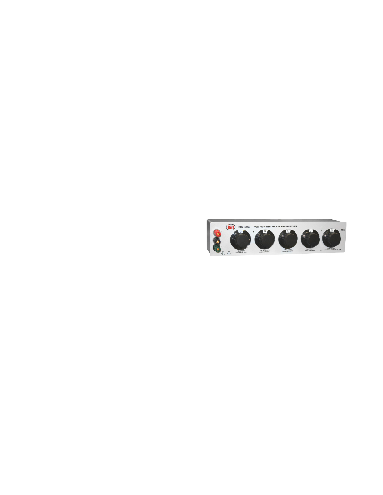
Figure 1-1: HRRS Series High Resistance
Decade Substituter