OfiTE 112-00 User manual

EP (Extreme Pressure) and
Lubricity Tester
#112-00 115 Volt
#112-00-1 230 Volt
Instruction Manual
Updated 1/31/2020
Ver. 8
OFI Testing Equipment, Inc.
11302 Steeplecrest Dr. · Houston, Texas · 77065 · U.S.A.
Tele: 832.320.7300 · Fax: 713.880.9886 · www.ote.com
©Copyright OFITE 2015

OFITE, 11302 Steeplecrest Dr., Houston, TX 77065 USA / Tel: 832-320-7300 / Fax: 713-880-9886 / www.ote.com 1
Introduction.....................................................................................2
Description......................................................................................3
Features...........................................................................................3
Components ...................................................................................4
Safety...............................................................................................6
Control Panel ..................................................................................7
Quick Start ......................................................................................8
Lubricity Test ..................................................................................9
Calculations - Coefcient of Friction ......................................... 11
Calculations - Lubricity Coefcient............................................12
EP Test...........................................................................................13
Reporting Test Results..............................................................16
Measurements and Calculations...............................................16
Disassembly .................................................................................18
Maintenance .................................................................................18
Transportation ...........................................................................18
Test Block..................................................................................18
Upper Main Shaft Bearing.........................................................20
Control Panel ............................................................................21
Belt Guard.................................................................................21
Calibration.....................................................................................22
Block Positioning.......................................................................22
Standardizing the Ring and Block.............................................24
Calibration Check......................................................................25
Warranty and Return Policy ........................................................26
Table of
Contents

OFITE, 11302 Steeplecrest Dr., Houston, TX 77065 USA / Tel: 832-320-7300 / Fax: 713-880-9886 / www.ote.com 2
Introduction When there is relative motion between two contacting bodies, frictional forces
that resist motion always come into play. Frictional resistance to rotation of
the drill string is called torque, and is especially enhanced when drilling a
deviated hole. Serious casing wear occurs in deep and ultra-deep wells. The
main inuential factor of casing wear is rotation of the drill pipe, horizontal
drilling, and tripping in and out of the hole. Many materials, such as Graphite,
Fine Mica, and Diesel or Crude Oil, have been used to improve lubricity.
Since evaluation of the various materials cannot realistically be done on the
drill string, a lubricity test was designed to simulate the speed of rotation of
the drill pipe and the pressure with which the pipe bears against the wall of
the bore hole. The OFITE combination EP (Extreme Pressure) and Lubricity
Tester is a high-quality instrument used to measure the lubricating quality
of drilling uids, provide data to evaluate the type and quantity of lubricating
additives that may be required, and predict wear rates of mechanical parts in
known uid systems.
Inch – Pounds
Torque is dened as the measure of force applied to produce rotational
motion (usually measured in foot-pounds). Torque is determined by
multiplying the applied force by the distance from the pivot point to the point
where the force is applied. Inch-pounds × 0.0833 = Foot-pounds
Torque is measured in units of distance multiplied by force. A force of ten lb
acting through a distance of two feet produces exactly the same torque (20
ft-lb) as a force of twenty lb acting through a distance of one foot.

OFITE, 11302 Steeplecrest Dr., Houston, TX 77065 USA / Tel: 832-320-7300 / Fax: 713-880-9886 / www.ote.com 3
Lubricity (Surface to Surface Drag) Test
The more common lubricity test measures uid resistance of various
lubricating additives. The standard lubricity coefcient test is run at 60 rpm
with 150 in-lb of force (the equivalent of approximately 600 psi (4,137 kPa)
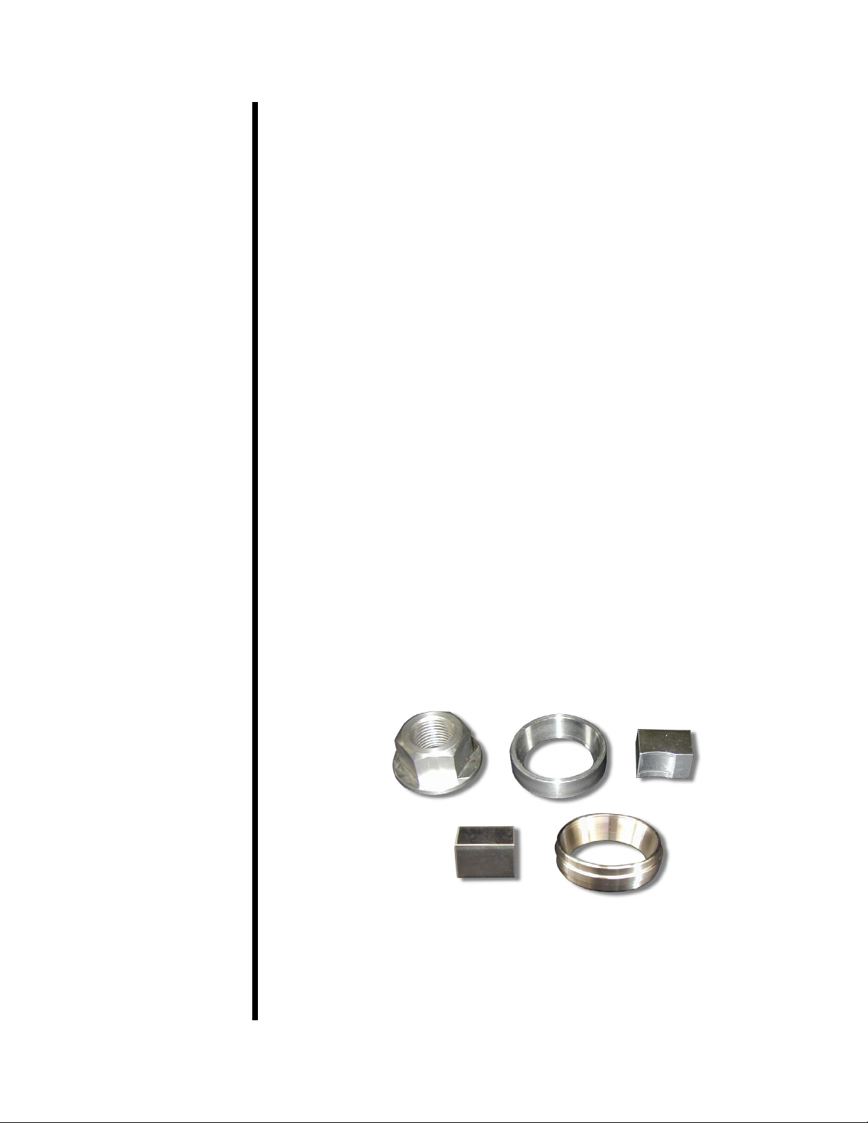
pressure of the intermediate uid) is applied to two hardened steel surfaces,
a rotating ring and a stationary block.
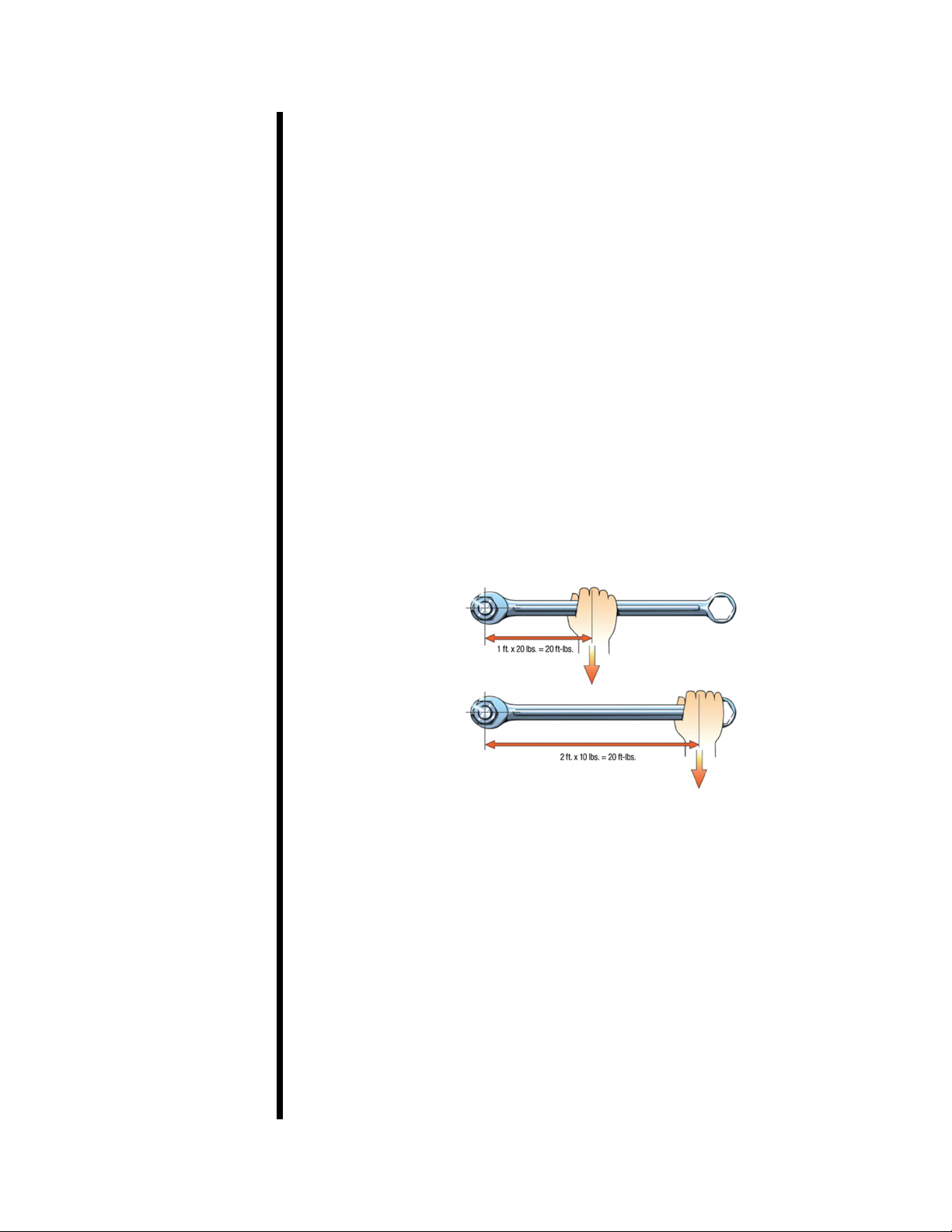
Friction is measured as the coefcient of friction (μ). The coefcient of friction
between two solids is dened as the frictional force of the load or the force
perpendicular to the surfaces. The coefcient of friction is independent of
the apparent areas of contact as long as this area is not so small as to break
through the lm. The force to overcome friction will be the same for a small
area as for a larger area. The force, F, required to slide the block and the ring
surfaces across each other at a given rate is measured by the power required
to turn the test ring shaft at a prescribed rate of revolutions per minute.
The Coefcient of Friction, μ =
EP (Extreme Pressure) Test
This test produces an indication of the lm strength of the uid being tested
by applying a measured force to a torque-sensitive bearing cup with the
torque arm. The EP test is typically run at a high shear rate (1,000 rpm) with
uid pressures ranging from 30,000 to 100,000 psi (206,820 - 689,400 kPa)
between the steel surfaces. Increasing pressure in in-lb of force is applied
until a seizure or pass is obtained.
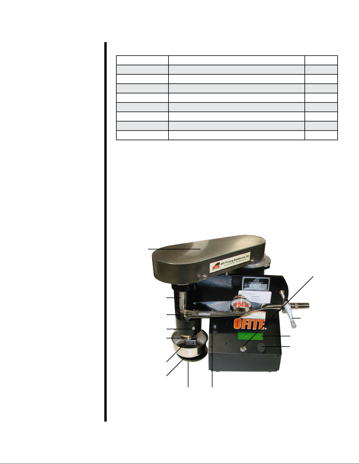
Digital Control
- The digital control panel provides more accurate data than older analog
models.
- The rotational speed (rpm) is automatically maintained as the torque is
increased, resulting in more accurate data collection and is less labor
intensive for the technician.
User-Friendly Interface
- The simple, intuitive interface makes testing quick and easy.
Functions include:
- Pre-Set Speeds: 60, 200, 600, and 1000 rpm
- Manual Speed Control
- Zeroing Torque and Time
- Maximum Speed: 1,000 rpm
- Maximum Torque: 600 in-lb
- Belt-Driven Motor: ½ HP, 90 Volt DC, 5.5 Amps
- Size: 19" × 15" × 14" (48.3 × 38.1 × 35.6 cm)
- Weight: 56 lb (25.4 kg)
Description
Meter Reading
Load or Force
Features

OFITE, 11302 Steeplecrest Dr., Houston, TX 77065 USA / Tel: 832-320-7300 / Fax: 713-880-9886 / www.ote.com 4
Components Included
#111-02-01 Test Ring for Lubricity Test
#111-04-01 Test Block for EP Test
#111-06-01 Test Ring for EP Test
#111-08-01 Test Block for Lubricity Test
#111-09 Sample Cup
#111-10 Torque Wrench
#111-16 Service Wrench, ¾"
#111-17 Service Wrench, 1¼"
#111-18 Combination Wrench,
#111-19 Grinding Compound, Silicone
Replacement Parts
#111-00-006 Belt, Timing
#111-00-007 Pulley, Timing 36 Teeth
#111-00-016 Motor, ½ HP, 5.5 Volts, Fan Cooled
#111-00-35 Retainer Nut
#111-00-37 Socket Extension
#111-00-38 Test Block Holder
#111-00-54 Assembly, Top Pulley Belt Guard
#111-00-55 Assembly, Cup Holder
#141-18 Thumb Screw
#164-32 Male Connector for Power Cable (230 Volt Only)
#172-09 Fuse, 10 Amp
Optional
#111-01 Padded Transport Case
#111-11 7× Measuring Magnier with Inch Scale
#112-50 Heat Cup
#152-59-2 Ultrasonic Cleaner, 115 Volt
#152-59-1 Ultrasonic Cleaner, 230 Volt
Top Row (Left to Right): Retainer Nut, Lubricity Test Ring, Lubricity Test Block
Bottom Row: EP Test Block (Left), EP Test Ring (Right)

OFITE, 11302 Steeplecrest Dr., Houston, TX 77065 USA / Tel: 832-320-7300 / Fax: 713-880-9886 / www.ote.com 5
Spare parts listings are intended to be used as a reference for future
purchases. Everyone’s consumable requirements will be different, and
replacement needs will depend on the number of tests performed on a daily
and/or weekly basis.
Part Number Description Quantity
#111-02-01 Test Ring for Lubricity Test 6
#111-04-01 Test Block for EP Test 6
#111-06-01 Test Ring for EP Test 6
#111-08-01 Test Block for Lubricity Test 6
#111-09 Sample Cup, stainless steel 1
#111-11 Measuring Magnier, 7×, with scale 1
#111-13 Grinding Compound, Grit 280, Fine, 16 oz 1
#111-14 Grinding Compound, Grit 120, Coarse, 16 oz 1
#111-00-SP Spare Parts Kit
Belt Guard
Main Shaft
Torque Arm
(#111-10)
Socket Head Bolt
Torque Bushing
Lock Nut
(#111-00-009)
Test Block Holder
(#111-00-38)
Sample Cup
(#111-09)
Cup Holder
Stand
(#111-00-55)
On – Off
Switch
Scroll Wheel
(#120-35-043)
LED Display
Screen
Torque Arm
Handle
(#111-00-21)
Exit or
Zero
Button

OFITE, 11302 Steeplecrest Dr., Houston, TX 77065 USA / Tel: 832-320-7300 / Fax: 713-880-9886 / www.ote.com 6
Safety The safe operation of the EP-Lubricity Tester requires that the technician be
thoroughly familiar with the proper operating procedures and the potential
hazards that are associated with operating the instrument. Therefore it is
important to read the instructions and store the instructions in a place known
to all laboratory personnel for frequent consultation.
Mechanical
The large silver colored belt guard protects the V-belt drive which is
connected to the main shaft assembly. Be very careful to keep hands, loose
clothing, and other objects away from all rotating parts and away from the
shielded belt guard. Do not put hands, ngers, or clothing in or near the
sample cup and test block while the machine is running.
Temperature
The test ring and test block will become hot due to friction generated during
the test. This is especially true when performing the Extreme Pressure (EP)
test. The test uid, stainless steel cup, and the ring and block can cause
severe burns if handled immediately after a test.
Clothing and Protective Gear
Wearing loose clothing should be avoided when operating equipment that
can potentially snag a loose cuff, collar, or tie. Always wear a lab coat when
performing tests and always wear protective eye glasses. Know in advance
where the eye-wash station is and the nearest exit from the laboratory and
the building in case of a re.
Electrical
This instrument is powered by 115 or 230 Volts AC. The motor is ½ HP. 90
Volts DC, and as with all electrical components there is a potential for danger.
Understanding safe test procedures while practicing a degree of common
sense when around electricity is vitally important.
The control panel contains electronic control components. The front panel
should never be opened to make repairs. Only a qualied OFITE technician
or an OFITE representative should perform repairs on these parts.
As with all electrical assemblies, make sure the machine is unplugged when
cleaning and/or moving it. Do not allow the LED panel to get wet. If test uid
or water is spilled on it be sure to wipe it clean immediately with a cloth.
Excessive water on the panel could cause the electrical components on the
underside of the panel to short out causing an electrical shock hazard.
At the end of the day ALL power cords should be unplugged from the wall
outlets, unless a test must be extended overnight.

OFITE, 11302 Steeplecrest Dr., Houston, TX 77065 USA / Tel: 832-320-7300 / Fax: 713-880-9886 / www.ote.com 7
Control Panel The instrument control panel consists of a display screen, a Scroll Wheel,
and an Exit button.
The Scroll Wheel spins clockwise and counter-clockwise. Spinning the wheel
scrolls through the menu and options. Pushing the Scroll Wheel in signals
acceptance.
The Exit button cancels any pending input and returns to the Main Menu.
Pushing the Exit button while on the Main Menu accesses the Zero Menu. To
access the Main Menu, push in the Scroll Wheel while on the home screen.
On the Main Menu you can set the motor speed to one of 5 preset values:
1. Set RPM to 0
2. Set RPM to 60
3. Set RPM to 200
4. Set RPM to 600
5. Set RPM to 1000
To access the Manual Speed Select, spin the Scroll Wheel while on the home
screen. From here you can increase the motor speed by spinning the wheel
clockwise and decrease it by spinning it counter-clockwise. By default, the
speed increases by 1 RPM for each increment of wheel spin. By pressing the
wheel in, you can increase this increment to 10 or 100 RPM.
SPIN: ADJUST RPM
ENTER: ADJUST RPM BY 1, 10, 100
To access the Zero Menu, press the Exit button while on the home screen.
From here you can set the test time and torque values to zero.
1. Zero the Test Time
2. Set Torque = 0.0
3. Restore Last Torque
To stop the motor, press the Scroll Wheel in twice.
Exit Button Scroll Wheel
On/Off Switch Display Screen

OFITE, 11302 Steeplecrest Dr., Houston, TX 77065 USA / Tel: 832-320-7300 / Fax: 713-880-9886 / www.ote.com 8
Quick Start 1. Check the instrument calibration. See page 22 for instructions.
2. Thoroughly clean the ring, block, block holder, and sample cup with
acetone.
3. Turn on the power and let the machine run for 15 minutes.
4. Place the test block in the holder. Do not let the ring and block touch.
5. Mix the test uid for at least ten minutes.
6. Set the motor speed to 60 rpm. See page 7 for more information
about using the Control Panel.
7. Fill the cup with uid and place it on the stand.
8. Raise the cup until the ring and block assembly are fully submerged.
Tighten the thumb screw.
9. Wait for the torque reading to stabilize. Then zero the torque reading on
the control panel.
10. Position the torque arm so it is inside the torque arm clamp.
11. Turn the torque adjust handle so the gauge reads 150 in-lb.
12. Zero the time on the control panel.
13. Let the machine run for 5 minutes.
14. Record the torque reading from the display screen.
15. Release the pressure on the ring and block.
16. Lower the cup and discard the uid.
17. Thoroughly clean the ring, block, block holder, and sample cup with
acetone.
18. Calculate the Lubricity Coefcient =
19. See page 11 for more information about calculating the Correction
Factor and the Lubricity Coefcient.
Meter Reading × Correction Factor
100

OFITE, 11302 Steeplecrest Dr., Houston, TX 77065 USA / Tel: 832-320-7300 / Fax: 713-880-9886 / www.ote.com 9
Lubricity Test The Lubricity Test should only be performed when the unit has been
successfully calibrated with deionized water and gives a Coefcient of
Friction reading of 34 ± 2. See page 24.
1. Clean the lubricity test ring (#111-02-01 with a at outer surface) and the
lubricity test block (#111-08-01 with a concave groove on one side) with
acetone and rinse both thoroughly with deionized water. All parts of the
machine in the sample area (block holder and shaft) must be completely
clean before starting a test.
Do not touch the metal contact areas with bare hands.
Removing the ring from the main shaft can change the alignment of the
contact area with the block. We recommend removing the ring only to
replace it (along with the block) or to switch between lubricity and extreme
pressure tests.
The Coefcient of Friction for water is 34 ± 2 at 60 rpm and 150
inch-pounds. Since not all metallurgical structures are the same nor is
the contact area the same between the metal parts, a variance of ± 2 is
allowed. When calculating the Coefcient of Friction, a correction factor of
34 divided by the water reading is used. A test should never be performed
if the Coefcient of Friction for water is outside this range.
2. Place the lubricity test ring squarely onto the tapered portion of the main
shaft. Secure the test ring retainer nut with a " wrench. Make sure the
ring seats squarely on the taper of the shaft.
3. Turn on the power and let the machine run for approximately 15 minutes.
4. Place the lubricity test block in the block holder with the concave side
facing out away from the torque shaft. Do not let the ring and block
contact each other.
Torque Bushing
(#111-00-36)
Sample Cup
(#111-09)
Locking Nut
(#111-00-009)Main Shaft
(#111-00-34)
Test Ring
Retainer Nut
(#111-00-35)
Thumb Screw
(#141-18)
Cup Stand

OFITE, 11302 Steeplecrest Dr., Houston, TX 77065 USA / Tel: 832-320-7300 / Fax: 713-880-9886 / www.ote.com 10
5. Set the motor speed to 60 rpm.
6. After the unit has been running for 15 minutes, zero the torque reading.
Run the unit approximately 5 more minutes and zero the torque again if
required.
7. Fill the stainless steel sample cup with the test uid (260
–280 mL) and
place it on the lowered cup stand. Raise the cup stand until the test ring,
test block, and block holder are fully submerged. Tighten the thumb screw
to secure the cup stand.
8. Zero the torque reading.
9. Position the torque arm so that it ts inside the concave portion of the
torque arm clamp. Check to make sure the test block has not fallen out of
the holder and is lying at the bottom of the cup.
10. Turn the torque adjust handle clockwise until the torque gauge on the arm
reads 150 inch-pounds.
Do not apply torque to the test ring unless it is submerged in uid.
11. Zero the time.
12. Let the machine run for 5 minutes and then record the torque reading.
Release the torque on the arm.
Test Block Holder
(#111-00-38)
Test Block
(#111-08)
Sample Cup
(#111-09 )
13. Adjust the motor speed back to Zero.
14. Lower the cup stand and discard the uid. Thoroughly wipe any remaining
uid from the sample cup, block, block holder, and test ring.

OFITE, 11302 Steeplecrest Dr., Houston, TX 77065 USA / Tel: 832-320-7300 / Fax: 713-880-9886 / www.ote.com 11
Lubricity Test
Calculations - Coefcient
of Friction
Torque Shaft Lever Arm
Torque Bushing
Lock Nut
Lubricity Block
1.5 Inches from Center of Block to Center
of Torque Bushing
150 Inch-pounds (Torque Wrench Reading)
1.5 Inches (Torque Shaft Lever Arm) =100 Pounds
Torque Reading
100
Coefcient of Friction = =
Coefcient of Friction =
Where:
F = The frictional force required to slide the block and ring surfaces across
each other at a given rate and is measured by the number of amperes
required to turn the test ring at a prescribed number of revolutions per
minute.
W = The load or force with which the test block is pressed against the test
ring through the torque arm. The standard test calls for 150 in-lb of
force, but the center of the test block is 1.5 inches from the center of
the torque bushing, resulting in an actual force of 100 lb applied.
F
W
F
W

OFITE, 11302 Steeplecrest Dr., Houston, TX 77065 USA / Tel: 832-320-7300 / Fax: 713-880-9886 / www.ote.com 12
Lubricity Test
Calculations - Lubricity
Coefcient
The Lubricity Coefcient is a more accurate measure as it considers the
variance (Correction Factor) the machine registers when calibrated against
deionized water.
Correction Factor
The Coefcient of Friction value for deionized water would be a constant if
the metallurgical structures of all rings and test blocks were the same, and
the same area between the two objects came into contact each time. At 60
rpm and 150 in-lb of load, the torque meter reading should be 34, resulting
in a Coefcient of Friction of 0.34. However since every ring and test block
is different a correction factor is required to achieve accurate results. To
calculate the correction factor, divide the standard meter reading for water
(34) by the actual meter reading, which you recorded in the lubricity test.
Correction Factor =
Meter Reading × Correction Factor
100 Pounds
Lubricity Coefcient =
Percent Torque Reduction
The percent of torque reduction is based upon the torque reading of a sample
that has been treated with a lubricant, relative to the same sample untreated.
Percent (%) Torque Reduction at a Given Load = × 100
Where:
AL= Torque reading of untreated mud under the same force as BL
BL= Torque reading of treated mud under the same force as AL
Standard Meter Reading for Deionized Water
Meter Reading Obtained in Deionized Water Calibration =34
Meter Reading (32 to 36)
AL-BL
AL

OFITE, 11302 Steeplecrest Dr., Houston, TX 77065 USA / Tel: 832-320-7300 / Fax: 713-880-9886 / www.ote.com 13
EP Test Before the test can be accurately run, the machine must be in proper
adjustment. To test for proper adjustment, or to run a standard test, proceed
through the following steps. Refer to page 7 for instructions on using the
control panel.
The EP test measures the lm strength of the liquid in two ways.
1. A Pass determines the amount of load or pressure the lubricant will hold
without a breakdown of lm strength.
2. A seizure represents the point where a complete breakdown of the uid
occurs resulting in a metal to metal contact as indicated by tearing or
galling of the metal surface on the block.
Procedure
1. Clean the EP test ring (#111-06-01 with a raised narrow surface) and the
EP test block (#111-04-01 cube with smooth surface) with acetone and
rinse them thoroughly with deionized water. All parts of the machine in the
sample area must be clean before starting a test.
Do not touch metal contact areas with bare hands.
Removing the ring from the main shaft can change the alignment of the
contact area with the block. We recommend removing the ring only to
replace it or to switch between lubricity and extreme pressure tests.
2. Stabilize the main shaft by inserting the shaft lock plunger into the hole in
the shaft.
3. Place the EP Test Ring squarely onto the tapered portion of the shaft.
Using a " wrench, secure the test ring retainer nut. Make sure the ring
seats squarely on the taper of the shaft.
4. Remove the shaft lock plunger from the hole in the shaft.
5. Turn the power on. Let the unit run for 15 minutes.
6. Press the scroll wheel twice to stop rotation. Place the EP Test Block in
the block holder.
7. Set the motor speed to 1,000 rpm. Check to make sure the block does
NOT fall out of the holder.
8. Zero the torque reading on the display (see page 7 for instructions).
9. Run the machine at 1,000 rpm for approximately 3 minutes, or until the
torque zero reading appears to stabilize and no longer drifts appreciably.
Zero the torque reading.

OFITE, 11302 Steeplecrest Dr., Houston, TX 77065 USA / Tel: 832-320-7300 / Fax: 713-880-9886 / www.ote.com 14
10. Position the torque arm so that the arm ts inside the concave portion of
the torque arm clamp.
11. Fill the stainless steel sample cup with test uid (260 – 280 mL) and
place it on the lowered cup stand. Raise the cup stand until the test ring,
test block, and block holder are submerged. Tighten the thumbscrew to
secure the cup stand.
Never apply torque to the test block until it is submerged in uid.
12. Rotate the torque adjust handle clockwise so that the reading on the torque
wrench increases at a rate of no more than 5 in-lb per second. Continue
until the torque wrench reading reaches:
a. The desired load (a “PASS”) occurs without seizing or.
b. Until a seizure occurs.
If a seizure occurs, quickly record the readings on the torque wrench and
on the display screen, then remove the load.
Due to the extreme friction between the ring and the block, the uid
will get very hot and may reach the boiling point.
A seizure is dened as tearing and galling (scarring) of the metal to metal
contact between the test ring and the test block surface. This represents a
complete breakdown of the extreme pressure lubricating ability of the uid
or mud under the test conditions. A seizure is identied by:
1. The initial and rapid (not slow) rise in the torque reading. It may
also appear as a sharp, substantial increase in the torque reading
(current), which then drops back to normal. This type of seizure
usually occurs at a relatively low torque reading or during tests of
highly abrasive muds or muds containing a high solids content.
2. An obvious change in the pitch (sound) of the machine (a rasping
sound).
3. The machine begins to vibrate as indicated by rapid uctuations of the
torque gauge needle.
After a seizure, the wear surface on the test block will be very large and
will appear rough and scarred.
If it is desirable to know how a uid behaves at a given torque:
12. Repeat steps 1 through 10 until a “PASS” is obtained. A “PASS” is
identied in one of two ways.
a. A ve minute run at a constant load during which the torque meter
reading remains essentially constant and the wear surface is small
and polished.

OFITE, 11302 Steeplecrest Dr., Houston, TX 77065 USA / Tel: 832-320-7300 / Fax: 713-880-9886 / www.ote.com 15
b. A ve minute run in which there is a moderate amount of torque
meter deection and the wear surface is moderate, and may either be
polished or dull, depending upon the abrasiveness of the test uid.
13. After removing and cleaning the test block, examine the test block for
wear. With the aid of a magnifying glass (#111-11), observe the scar left
on the block by the test ring.
If the scar is rectangular, the test block is properly aligned in the holder.
Your test is complete. If the scar is triangular or trapezoidal, the alignment
is off and must be corrected. Refer to the “Block Positioning” section on
page 22 for instructions.
Improperly Positioned Test Block
(Note: Two tests may be performed
on each face)
Properly Positioned Test Block

OFITE, 11302 Steeplecrest Dr., Houston, TX 77065 USA / Tel: 832-320-7300 / Fax: 713-880-9886 / www.ote.com 16
EP Test
Reporting Test Results
EP Test
Measurements and
Calculations
Width
Length
1. Record the lowest torque wrench reading (in in-lb) at which the seizure
occurred.
2. Record the average torque reading on the screen at which the seizure
occurred.
3. Record the following at the conclusion of a pass or if a 5-minute test does
not produce a seizure.
a. Torque meter reading in in-lb.
b. Scar width in inches.
c. Film strength in psi. This value must be calculated.
d. Torque reading on the display screen in pounds divided by 10 =
Average current in amps.
To calculate the Film Strength of the test uid:
1. To measure the scar length and width on the block, use a magnier (#111-
11) calibrated to read 0.005" (90.0127 cm). Place the magnier at the
center of the scar parallel to the edges.
a. The width of the scar is parallel to the long axis of the block.
b. The length of the scar is parallel to the small axis of the block.

OFITE, 11302 Steeplecrest Dr., Houston, TX 77065 USA / Tel: 832-320-7300 / Fax: 713-880-9886 / www.ote.com 17
T (in-lb)
1.5 × L (in.) × W (in.)
EP Block – Good Seizure Scarring
2. To calculate the pressure on the block:
a. Compute the total area of the scar on the block. Multiply the width of
the scar (in inches) by the length of the scar (in inches). If the scar is
trapezoidal in shape, use the average width of the scar.
b. Calculate the force acting on the scar area. Divide the torque meter
dial reading (in inch pounds) at which a Pass was obtained by 1.5 (1.5
is the travel distance of the arm).
c. Calculate the pressure on the test block at the time the test was
stopped. Divide the force acting on the scar (B above) by the area of
the scar (A above). This pressure is the lm strength of the uid.
In equation form it is as follows:
P =
Where:
P = Film Strength (psi)
T = Torque Meter Dial Reading (in-lb)
W = Scar Width (inches)
L = Scar Length (inches)

OFITE, 11302 Steeplecrest Dr., Houston, TX 77065 USA / Tel: 832-320-7300 / Fax: 713-880-9886 / www.ote.com 18
Disassembly
Maintenance
Transportation
Damaged
Block
Holder
Maintenance
Test Block
1. Turn the power off.
2. Lower the cup stand and turn the torque arm clamp up and away.
3. Swing the torque arm back to allow removal of the test block.
4. Remove and thoroughly rinse the test block with deionized water.
5. Remove the cup and discard the test uid.
6. Remove the retaining nut and test ring.
7. Use acetone, deionized water, and a brush to clean the entire test area,
including the test ring, test block, and block holder. To prevent rust,
ensure that the entire unit is clean and dry. If the machine is to be stored
for a long period of time, coat all components with oil.
The EP Lubricity Tester is intended to remain stationary on a laboratory
bench. If it must be transported, the torque arm should be removed from the
unit, and not simply tightened down. If it is being shipped, it must be encased
inside a wooden crate with the unit bolted to the bottom of the crate. This
machine is heavy (56 pounds) and if dropped the frame may warp, which
may result in a total replacement of the unit.
After reaching the desired rpm, recheck the test block to make sure it is still
inside the holder. Sometimes the vibration of the machine will cause the block
to fall out of the Test Block Holder (#111-00-38), ending up in the bottom of
the cup. If the technician does not notice the block is out of the holder and the
torque arm is depressed the test block holder may become damaged.

OFITE, 11302 Steeplecrest Dr., Houston, TX 77065 USA / Tel: 832-320-7300 / Fax: 713-880-9886 / www.ote.com 19
To Remove the Test Block Holder:
1. Loosen set screw at the back of the test block holder.
2. Gently tap the test block holder off the torque bushing.
3. If the test block holder does not come loose, it will be necessary to loosen
the socket head bolt on the housing so the entire torque bushing comes
out.
a. Lock the bushing securely on a bench vise.
b. Gently tap the test block holder loose from the shaft.
Housing Socket
Head Bolt
Test Block Holder
Set Screw
Lubrication
The roller bearing in the main shaft may occasionally need to be greased.
If a squeaking noise is coming from the main shaft, add a high-temperature
bearing grease (such as Lubricate No. 12601) via the opening located on the
lower back of the housing behind the lower main shaft.
Other manuals for 112-00
1
This manual suits for next models
1
Table of contents
Other OfiTE Test Equipment manuals