IKONIX 3145 Operation manual


DECLARATION OF CONFORMITY
Manufacturer: Associated Research, Inc.
Address: 28105 North Keith Dr.
Lake Forest, IL 60045
USA
Product Name: HYAMPIII DC Ground Bond Tester
Model Number: 3145
Conforms to the following Standards:
Safety: IEC61010-1:2010
EN61010-1:2010
EMC: EN61326-1:2013(EN55011:2009+A1:2010 CLASS A,
EN61000-3-3:2008, IEC61000-4-2:2008, IEC61000-4-
3:2006/A1:2007/A2:2010, IEC61000-4-
4:2004/A1:2010,IEC6100-4-5:2005, IEC61000-4-6:2008,
IEC61000-4-8:2009, IEC61000-4-11:2004)
Supplementary Information
The product herewith complies with the requirements of the Low Voltage
Directive 2014/55/EU, the European Council Directive 2014/30/EU and the RoHS
Directive 2011/65/EU with respect to the following substances: Lead (Pb),
Mercury (Hg), Cadmium (Cd), Hexavalent chromium (Cr (VI)), Polybrominated
biphenyls (PBB), Polybrominated diphenyl ethers (PBDE), Deca-BDE included.
The technical file and other documentation are on file with Associated
Research, Inc.
______________________________
Joseph Guerriero, President
Associated Research, Inc.
Lake Forest, Illinois USA
April 21, 2017

____________________________________________________________________________
i
TABLE OF CONTENTS
1. INTRODUCTION ..............................................................................................3
1.1. Warranty Policies...........................................................................................3
1.2. Safety Symbols..............................................................................................4
1.2.1. Product Marking Symbols..................................................................4
1.2.2. Caution and Warning Symbols..........................................................4
1.3. Glossary of Terms.........................................................................................4
1.4. Safety ..............................................................................................................6
1.4.1. Service and Maintenance ..................................................................6
1.4.2. Test Station..........................................................................................7
1.4.3. Test Operator.......................................................................................8
1.5. Key Features and Benefits...........................................................................9
2. GETTING STARTED......................................................................................10
2.1. Unpacking and Inspection..........................................................................10
2.1.1. Packaging...........................................................................................10
2.1.2. Contents of Carton............................................................................10
2.2. Installation.....................................................................................................11
2.2.1. Work Area...........................................................................................11
2.2.2. Power Requirements........................................................................11
2.2.3. Basic Connections ............................................................................12
2.2.4. Environmental Conditions................................................................12
3. SPECIFICATIONS AND CONTROLS............................................................14
3.1. 3145 Specifications.....................................................................................14
3.2. Instrument Controls.....................................................................................17
3.2.1. Front Panel Controls for 3145.........................................................17
3.2.2. Rear Panel Controls for 3145..........................................................18
4. PROGRAMMING INSTRUCTIONS................................................................20
4.1. Power Up......................................................................................................20
4.1.1. Memory, Step and Connected Step Indicator...............................20
4.1.2. Main Menu..........................................................................................20
4.1.3. Results, Tests and System Selections ..........................................21
4.2. System Setup...............................................................................................22
4.2.1. System Setup Soft keys...................................................................23
4.2.2. System Parameters ..........................................................................23
4.2.3. Default System Parameters.............................................................28
4.2.4. Memory, Step, and Default System Parameter Initialization......28
4.3. Test Setup ....................................................................................................28
4.3.1. Test Setup Soft Keys........................................................................29
4.3.2. Test Parameters................................................................................29
4.3.3. Default Parameters...........................................................................30

____________________________________________________________________________
ii
4.3.4. Setting Up a Test...............................................................................30
5. OPERATING INSTRUCTIONS.......................................................................32
5.1. Instrument Connections .............................................................................32
5.1.1. Test Leads..........................................................................................32
5.1.2. Adapter Box Connections (Adapter box is sold separately).......33
5.1.3. Interlock Connector...........................................................................33
5.2. Performing a Test........................................................................................34
5.3. Test Metering...............................................................................................34
5.4. Results Screens...........................................................................................34
5.5. Error Messages ...........................................................................................35
6. CONNECTION OF REMOTE I/O....................................................................37
6.1. Remote Signal Outputs ..............................................................................37
6.2. Signal Inputs of Remote I/O and Memory Access.................................39
6.3. HYAMP III Connected to HYPOT III........................................................42
7. BUS REMOTE INTERFACE...........................................................................44
8. OPTIONS........................................................................................................49
9. INSTRUMENT VERIFICATION......................................................................50
9.1. Verification Initialization..............................................................................50
9.2. Verification Menu.........................................................................................50
10. CALIBRATION PROCEDURE .....................................................................52
10.1. Warranty Requirements...........................................................................52
10.2. Calibration Initialization ............................................................................52
10.2.1......................................................................................................Cali
bration of Parameters...............................................................................................53
10.2.2......................................................................................................Cali
bration of Ground Bond DC Current for 3145.......................................................53
10.2.3......................................................................................................Cali
bration of Ground Bond DC Voltage for 3145.......................................................54
11. REPLACEMENT PARTS LIST.....................................................................56

____________________________________________________________________________
3
1. INTRODUCTION
1.1. Warranty Policies
Associated Research, Inc., certifies that the instrument listed in this manual meets or
exceeds published manufacturing specifications. This instrument was calibrated using
standards that are traceable to the National Institute of Standards and Technology
(NIST).
Your new instrument is warranted to be free from defects in workmanship and material
for a period of (3) year from the date of shipment. You must complete the online
registration at http://www.asresearch.com/support/register/login.aspx or call 1-800-
858-TEST (8378) ext. 0 to register over the phone.
5-Year Program
All Associated Research instruments include the opportunity to extend the standard
warranty for up to a period of 5 years. Returning instruments to Associated Research
for their annual calibration and inspection will extend the instrument's warranty for an
additional year. This warranty is extendable for up to five years and annual returns
must be made in succession starting one year after the original purchase date. There
are no additional costs for the 5 year product warranty. The only annual costs to the
customer are the standard calibration fees and shipping costs. This extended warranty
is non-transferable and is offered only to the original purchaser. A return material
authorization (RMA) must be obtained from Associated Research, Inc. before
returning this instrument for warranty service. Please contact our customer support
center at 1-800-858-TEST (8378) to obtain an RMA number. It is important that the
instrument is packed properly for safe transport. Please contact our customer support
center for proper instructions on packaging. Damages sustained as a result of
improper packaging will not be honored. Transportation costs for the return of the
instrument for warranty service must be prepaid by the customer. Associated
Research, Inc. will assume the return freight costs when returning the instrument to
the customer. The return method will be at the discretion of Associated Research,
Inc.
____________________________________________________________________________
4
Operator Modifications
Any non-authorized modifications, tampering or physical damage will void this
warranty. Elimination of any connections in the earth grounding system or bypassing
any safety systems will void this warranty. This warranty does not cover accessories
not of Associated Research, Inc. manufacture. Parts used must be parts that are
recommended by Associated Research, Inc. as an acceptable specified part. Use of
non-authorized parts in the repair of this instrument will void the warranty.
Associated Research, Inc. will not be responsible for any injuries sustained due to
unauthorized equipment modifications or use of parts not specified by Associated
Research, Inc. Instruments returned to Associated Research, Inc. with unsafe
modifications will be returned to their original operating condition at the customer’s
expense.
1.2. Safety Symbols
1.2.1. Product Marking Symbols
Product will be marked with this symbol when it is necessary to refer to the
operation and service manual in order to prevent injury or equipment
damage.
Product will be marked with this symbol when hazardous voltages may be
present.
Product will be marked with this symbol at connections that require earth
grounding.
1.2.2. Caution and Warning Symbols
Calls attention to a procedure, practice, or condition that could
possibly cause bodily injury or death.
Calls attention to a procedure, practice, or condition that could
possibly cause damage to equipment or permanent loss of data.
1.3. Glossary of Terms
(As used in this manual)

____________________________________________________________________________
5
Alternating Current, AC: Current that reverses direction on a regular basis. Utility power is
usually generated in the form of a sinusoid at a frequency of 60 times per second in the United States
and 50 times per second in other countries.
Arc: A partial momentary breakdown due to the force of a strong electric field on closely spaced
conductors, sometimes evidenced by corona or a luminous flashover.
Breakdown: The failure of insulation to effectively prevent the flow of current. If the test voltage is
gradually raised, breakdown will begin suddenly at a certain voltage level and current flow will not be
directly proportional to voltage. Once a breakdown occurs, especially for a period of time, the next
gradual application of voltage will often cause a breakdown to begin at a lower voltage.
Conductor: A solid or liquid material which permits the flow of electrons. A material which has a
volume resistivity of no more than 103 Ω-cm.
Current: The movement of electrons through a conductor. Current is measured in amperes (A),
milliamperes (mA), microamperes (uA). Symbol = I
Dielectric: An insulating material that is positioned between two conductive materials in such a way
that a charge or voltage may appear across the two conductive materials.
Direct Current, DC: Current that flows in one direction only. The source of direct current is said to
be polarized and has one terminal that is always at a higher potential than the other.
Frequency: The number of cycles an AC waveform repeats over time. Usually given in Hertz (Hz).
Ground: Refers to the point of low potential in a circuit to which all other voltages are referenced.
May or may not be tied to the earth. Also referred to as Earth.
Hot: Used to refer to the test lead or output side of an instrument that is at high potential.
Impedance: The property of capacitive or inductive items to limit certain frequencies.
Insulation: Gas, liquid or solid material which has a volume resistivity of at least 1012 Ω-cm and is
used for the purpose of restricting current flow between conductors.
Leakage: AC or DC current flow through insulation and over its surfaces. Current flow is directly
proportional to voltage. The insulation is thought of as a constant impedance unless breakdown
occurs.
Neutral: The point of low potential in a circuit to which all other voltages are referenced. Also known
as Common.
Peak Current: The maximum amplitude of an AC current waveform. For a sinusoid, 1.414 x the
RMS value.
Power: The amount of work performed by an energy source over time, given in Watts (W).

____________________________________________________________________________
6
The HYAMP III produces
voltages and currents that
can cause harmful or fatal
electric shock. To prevent
accidental injury or death,
these safety procedures
must be strictly observed
when handling and using the
test instrument.
This instrument
meets UL
requirements for
audible and visual
failure indication.
SAFETY
PF (Power factor): Power Factor = W/VA where W =Watts (Real Power) and VA =Volts x Amps
(apparent power). It is important to note that the closer the power factor is to "1" the more resistive the
DUT is. The closer the power factor is to 0 the more reactive (inductive or capacitive) the DUT is.
Reactive Current: The current component due to the reactive impedance of a load. Also called
imaginary current.
Real Current: The current component due to the resistance of a load.
Resistance: The property of a substance that impedes current and results in the dissipation of
power in the form of heat. The practical unit of resistance is the ohm (Ω). Symbol = R
Return: The path by which current returns to a source.
RMS: The Root Mean Squared value of a voltage or current waveform. An RMS waveform delivers
the same amount of energy to a load as a DC waveform of the same value. For a sinusoid, the RMS
value is .707 x the peak value.
Total Current:The vector sum of the real current component and the reactive current component
produced by an applied voltage.
VA: A rating of instantaneous power found by multiplying an instrument’s maximum output current by
its maximum output voltage.
Voltage: The force which causes current through an electrical conductor, given in volts (V).
Symbol = V
1.4. Safety
This product and its related documentation
must be reviewed for familiarization with
safety markings and instructions before
operation.
This product is a Safety Class I instrument
(provided with a protective earth terminal).
Before applying power verify that the
instrument is set to the correct line voltage
(115 or 230) and the correct fuse is
installed.
This product carries an NRTL (Nationally
Recognized Testing Laboratory) and
comes equipped with an audible and visual failure indicator.
1.4.1. Service and Maintenance
User Service

____________________________________________________________________________
7
ESD TESTING
To prevent electric shock do not remove the instrument cover. There are no internal
user serviceable parts. Routine maintenance or cleaning of internal parts is not
necessary. Avoid the use of cleaning agents or chemicals on the instrument, as some
chemicals may damage plastic parts or lettering. Any external cleaning should be
done with a clean, dry or slightly damp cloth. Schematics, when provided, are for
reference only. Refer servicing and certification to an Associated Research, Inc.
authorized service center.
Service Interval
Associated Research, Inc. will not be held liable for injuries suffered if the instrument
is not properly maintained and safety checked annually. See section 1.1. Warranty
Policies for more information.
1.4.2. Test Station
Location
Select an area away from the mainstream of activity where employees do not walk
while performing their normal duties. If this is not practical because of production line
flow, then the area should be roped off and marked for HIGH VOLTAGE TESTING.
No employees other than test operators should be allowed inside.
If benches are placed back-to-back, be especially careful about the use of the bench
opposite the test station. Signs should be posted: “DANGER –HIGH VOLTAGE
TEST IN PROGRESS –UNAUTHORIZED PERSONNEL KEEP AWAY.”
Work Area
When possible, use the instrument on a non-conducting table or workbench. If you
cannot avoid using a conductive surface, be certain that it is connected to a good
earth ground and the high voltage connection is
insulated from the grounded surface.
There should not be any metal in the work area
between the operator and the location where
products being tested will be positioned. Any other
metal in the work area should be connected to a
good ground, never left “floating”.
Keep the area clean and uncluttered. All test
equipment and unnecessary test leads should be
ASSOCIATED RESEARCH, INC.
13860 WEST LAUREL DRIVE
LAKE FOREST, IL 60045-4546 U.S.A.
Electrical safety tests
should not be
performed in or around
ESD testing areas.
ESD methods should
not be employed during
electrical safety testing,
as this could cause a
hazardous condition for
equipment and test
operators.
____________________________________________________________________________
8
KEY SAFETY POINTS TO
REMEMBER
removed from the test bench and put away. It should be apparent to both the operator
and to any observers which product is under test, which product is waiting to be tested
and which product has already been tested.
Power
Power to the test station should be arranged so that it can be shut off by one
prominently marked switch located at the entrance to the test area. In case of an
emergency, anyone should be able to cut off the power before entering the test area
to offer assistance.
More Information
For more information on setting up a safe work station, please visit the Events and
Training section of our website at http://www.asresearch.com/events-
training/Default.aspx
1.4.3. Test Operator
This instrument generates voltages and currents that can cause
harmful or fatal electric shock and must only be operated by a
skilled worker trained in its use. The operator should
understand the electrical fundamentals of voltage, current, and resistance.
Rules
Operators should be thoroughly trained to follow all national safety standard
guidelines for electrical safety testing in the workplace. Defeating any safety system
should be considered a serious offense with severe penalties. Allowing unauthorized
personnel in the area during a test should also be dealt with as a serious offense.
Test operators should be familiar with methods to properly discharge a device under
test in case test leads become disconnected during testing.
Refer to the following standards for more information:
NFPA 70E
OSHA 1910 subpart (S)
EN50191
Dress
Operators should not wear jewelry that could accidentally complete a circuit.
ESD protocols should not be observed while performing
electrical safety
tests.
Intentionally grounding the test
operator could lead to a harmful or
fatal electric shock.
Keep unqualified and
unauthorized personnel away
from the test area.
Arrange the test station in a safe
and orderly manner.
In case of any problem, turn off
the high voltage first.

____________________________________________________________________________
9
Medical Restrictions
Personnel with heart ailments or devices such as pacemakers should be informed that
the voltages and currents generated by the instrument are very dangerous. If
contacted, the instrument may cause heart-related problems. Please have the test
operator consult a physician for recommendations.
1.5. Key Features and Benefits: HYAMP III
THE FIRST MANUAL
GROUND BOND
INSTRUMENT WITH AN
ENHANCED GRAPHIC LCD
Provides the operator with an easy-to-use
interface, eliminating the need to decipher cryptic
abbreviations. The graphic display makes testing
safer, easier and more reliable than ever before.
SECURITY ACCESS
Limit user access so that only authorized
personnel with a security code can change test
parameters.
STORAGE OF UP TO 10
DIFFERENT TEST
PROGRAMS
Store test parameters and quickly recall them for
each of the different products that need to be
tested. Memories can also be linked to run multi-
step tests.
INTERCONNECTION WITH
HYPOT III
Connect a HYAMP III and a Hypot III to form a
complete test system. The test system can be
configured to perform sequential Ground Bond
and Dielectric Withstand tests, or run both
simultaneously.
FOUR WIRE MEASUREMENT
(KELVIN METHOD) AND
MILLIOHM OFFSET
CAPABILITY
The Kelvin four wire measurement technique
eliminates test lead resistance. The milliohm
offset function allows for the use of longer test
leads without compromising the test results.
PLC REMOTE INPUTS AND
OUTPUTS
Two standard 9 pin interfaces provide inputs and
outputs for simple PLC relay control. Outputs
include: PASS, FAIL, RESET and TEST IN
PROCESS signals. Inputs include: TEST,
INTERLOCK, RESET and remote recall of
MEMORY 1, 2 and 3.
WITHSTAND PROCESSING
INDICATOR
As a safety precaution, the enhanced graphic
LCD indicates when the high voltage from the
Hypot III is being applied to the device under test
SOFTWARE CALIBRATION
CONTROL
HYAMP III can be completely calibrated without
removing any covers and exposing the technician
to hazardous voltages.
NO LOAD SETUP OF
OUTPUT CURRENT
Set output current parameters without activating
the output.

____________________________________________________________________________
10
2. GETTING STARTED
Introduction
This section contains information for the unpacking, inspection, preparation and
storage of your Associated Research, Inc., product.
2.1. Unpacking and Inspection
2.1.1. Packaging
Your instrument was shipped in a custom foam insulated container. If the shipping
carton is damaged, inspect the contents for visible damage such as dents, scratches
or a broken display. If the instrument is damaged, notify the carrier and Associated
Research, Inc.’s customer support department. Please save the shipping carton
and packing material for the carrier’s inspection. Our customer support
department will assist you in the repair or replacement of your instrument. Please do
not return your product without first notifying us and receiving an RMA (return material
authorization) number. To receive an RMA number, please contact our customer
support department at 1-800-858-TEST (8378).
2.1.2. Contents of the Carton
Inside the carton should be the following:
DESCRIPTION
AR PART NUMBER
HYAMP III Instrument
3145
Cable ASSY High
Current Output
38489 Current with Kelvin
Cable ASSY High
Current Return
38490 Return with Kelvin
Fuse
38503, 10 Amp, Slow Blow
250VAC
Line Cord
33189 Standard
Interlock Connector
38075
Only accessories that meet the manufacturer’s specifications
shall be used.

____________________________________________________________________________
11
3145 Carton Contents
2.2. Installation
2.2.1. Work Area
Locate a suitable testing area and be sure you have read all
safety instructions for the operation of the instrument and
suggestions on the test area setup in section 1.4. Safety. Make
sure the work area you choose has a three-prong grounded outlet capable of
supplying the necessary input current to the power source. Be sure the outlet has
been tested for proper wiring before connecting the instrument to it.
2.2.2. Power Requirements
This instrument requires a power source of either 100-120 volts AC ± 10%, 50/60 Hz
single phase or 200-240 volts AC ±10%, 50/60 Hz single phase. The instrument will
automatically detect the input voltage being applied to it. See section 3.2.2. Rear
Panel Controls for an image of the rear panel.
The HYAMP III must be connected to a good ground. Be
certain that the power wiring is properly polarized and that the
proper low resistance bonding to ground is in place.

____________________________________________________________________________
12
2.2.3. Basic Connections
Power Cable
The instrument is shipped with a line cord containing a protective earth ground. When
the line cord is connected to an appropriate AC power source the cable will connect
the chassis to earth ground.
The main plug shall only be inserted in a socket outlet with a
protective ground (earth) contact. This protective ground must
not be defeated by the use of an extension cord without a
protective conductor.
Do not replace the included line cord with an improperly rated
cord. A UL listed and CSA labeled power cord must be used
with the instrument in the United States and Canada. The power
cord must include a NEMA5-15 style male plug, SVT or SJT cord sets, and be rated
for at least 125VAC, 10A. Number 18 gauge wire or larger must be used.
Return Connection
When the instrument’s return is grounded, any internal and external stray leakage will
be monitored due to currents that flow from high voltage to earth ground (such as from
high voltage to the chassis of the instrument). These currents are inherent and will
cause errors when trying to monitor very low leakage currents in the microamp range.
The output power supplies of this instrument are referenced directly to earth ground.
Any conductor that completes a path between the high voltage and earth ground will
form a completed circuit.
2.2.4. Environmental Conditions
This equipment is intended for indoor use only. The equipment has been evaluated
according to Installation Category II and Pollution Degree 2 as specified in IEC 664.
This instrument may be operated in environments with the following limits:
Temperature….................. 32° - 104° F (0° - 40°C)
Relative humidity…........... 0 – 80%
Altitude…......................... 6560 feet (2,000 meters)
NOTE: Keep the ventilation slits uncovered during operation. Failure to do so
could cause the instrument to overheat and may damage internal components.
Storage and Shipping Environment
This instrument may be stored or shipped in environments with the following limits:
Temperature….................. -40° - 167° F (-40° - 75°C)
Altitude…......................... 50,000 feet (15,240 meters)
The instrument should also be protected against temperature extremes that may
cause condensation within the instrument.

____________________________________________________________________________
13
Failure to operate this instrument within the specified conditions
could result in damage.
More Information
For more information on test operator and workstation safety please visit the Events
and Training section of our website at http://www.asresearch.com/events-
training/Default.aspx
____________________________________________________________________________
14
3. SPECIFICATIONS AND CONTROLS
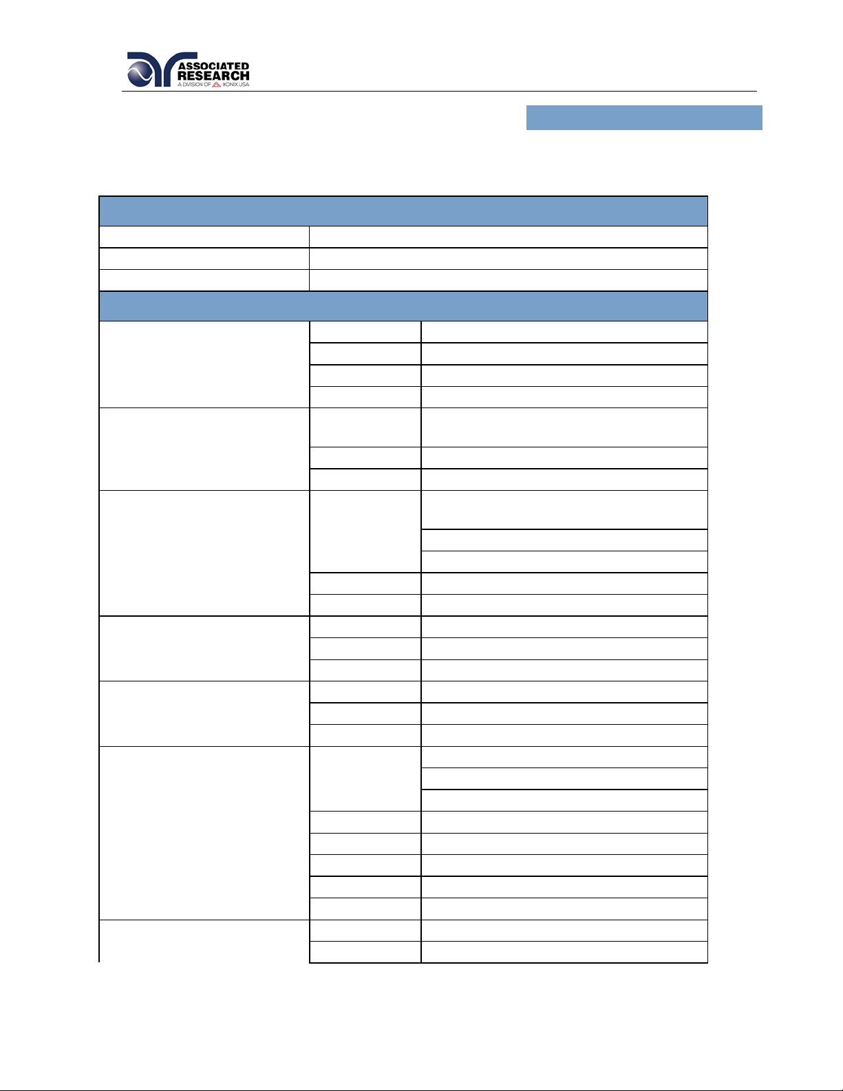
3.1. 3145 HYAMP III Functional Specifications
INPUT
Voltage
100-120 / 200-230 VAC 10, auto-detection
Frequency
50/60 Hz 5%
Fuse
10 Amp, slow-blow 250 V AC
TEST MODE
Output Rating
Current:
1.00 –40.00 Amps DC
Resolution:
0.01 Amp/step
Regulation:
(2of setting 2 counts)
Voltage:
8 Volts DC, maximum
Dwell Time Setting
Range:
0 and 0.5 –999.9 seconds,
0 for continuous running
Resolution:
0.1 second
Accuracy:
(0.1of setting 0.05 seconds)
Maximum and Minimum
Limits
Range:
0 –600 mΩfor 1.00 –10.00 Amps
0 –200 mΩ for 10.01 –30.00 Amps
0 –150 mΩ for 30.01 –40.00 Amps
Resolution:
1 mΩ
Accuracy:
Same as Ohmmeter Display
Offset Capability
Range:
0 –100 mΩ
Resolution:
1 mΩ
Accuracy:
(2of setting 2 counts)
Current Display
Range:
0.00 –40.00 Amps
Resolution:
0.01 Amp
Accuracy:
(3of reading 0.03 Amps)
Ohmmeter Display
Range:
0 –150 mΩ for 30.01 –40.00 Amps
0 –200 mΩ for 10.01 –30.00 Amps
0 –600 mΩ for 6.00 –10.00 Amps
Resolution:
1 mΩ
Accuracy:
(2of reading 2 counts)
Range:
0 –600 mΩ for 1.00 –5.99 Amps
Resolution:
1 mΩ
Accuracy:
(3of reading 3 counts)
Timer Display
Range:
0.0 –999.9 seconds
Resolution:
0.1 seconds

____________________________________________________________________________
15
Accuracy:
(0.1of reading 0.05 seconds)

____________________________________________________________________________
16
GENERAL
Safety Agency Listing
CE, cTUVus, RoHS2
Remote Control And Signal
Output
The following input and output signals are provided
through two 9 pin D type connectors;
1. Remote control: Test, Reset, Interlock, and
Withstand Processing.
2. Remote recall of memory program #1, #2 and #3.
3. Outputs: Pass, Fail, Test-in-Process, Start Out,
and Reset Out.
Program Memory
10 Memories, 3 steps per memory, all steps within a
memory are linkable.
Security
Key Lock capability to avoid unauthorized access to
all test parameters. Memory Lock capability to avoid
unauthorized access to memory locations.
Verification System
Built-in software driven verification menu to test fault
detection circuits.
Display
128 x 64 dot resolution with front panel contrast
setting.
Alarm Volume Setting
Front panel adjustable volume setting with 10 set
points.
Line Cord
Detachable 6 ft. (1.80m) power cable terminated in a
three prong grounding plug.
Mechanical
Tilt up front feet.
Dimensions: (W x H x D) 8.5 x 3.5 x 15.0 in. (215 x 89
x 370 mm) includes feet.
Weight: 11.55 lbs
Environmental
Operating Temperature: 32- 104F (0- 40C)
Relative Humidity - 0 to 80%
Calibration
Traceable to National Institute of Standards and
Technology (NIST). Calibration controlled by
software. Adjustments are made through front panel
keypad in a restricted access calibration mode.
Calibration information stored in non-volatile memory.
Why use the term “Counts”?
Associated Research publishes some specifications using COUNTS which allows us to provide
a better indication of the tester’s capabilities across measurement ranges. A COUNT refers to
the lowest resolution of the display for a given measurement range. For example, if the
resolution for voltage is 1V then 2 counts = 2V.
____________________________________________________________________________
17
3.2. Instrument Controls
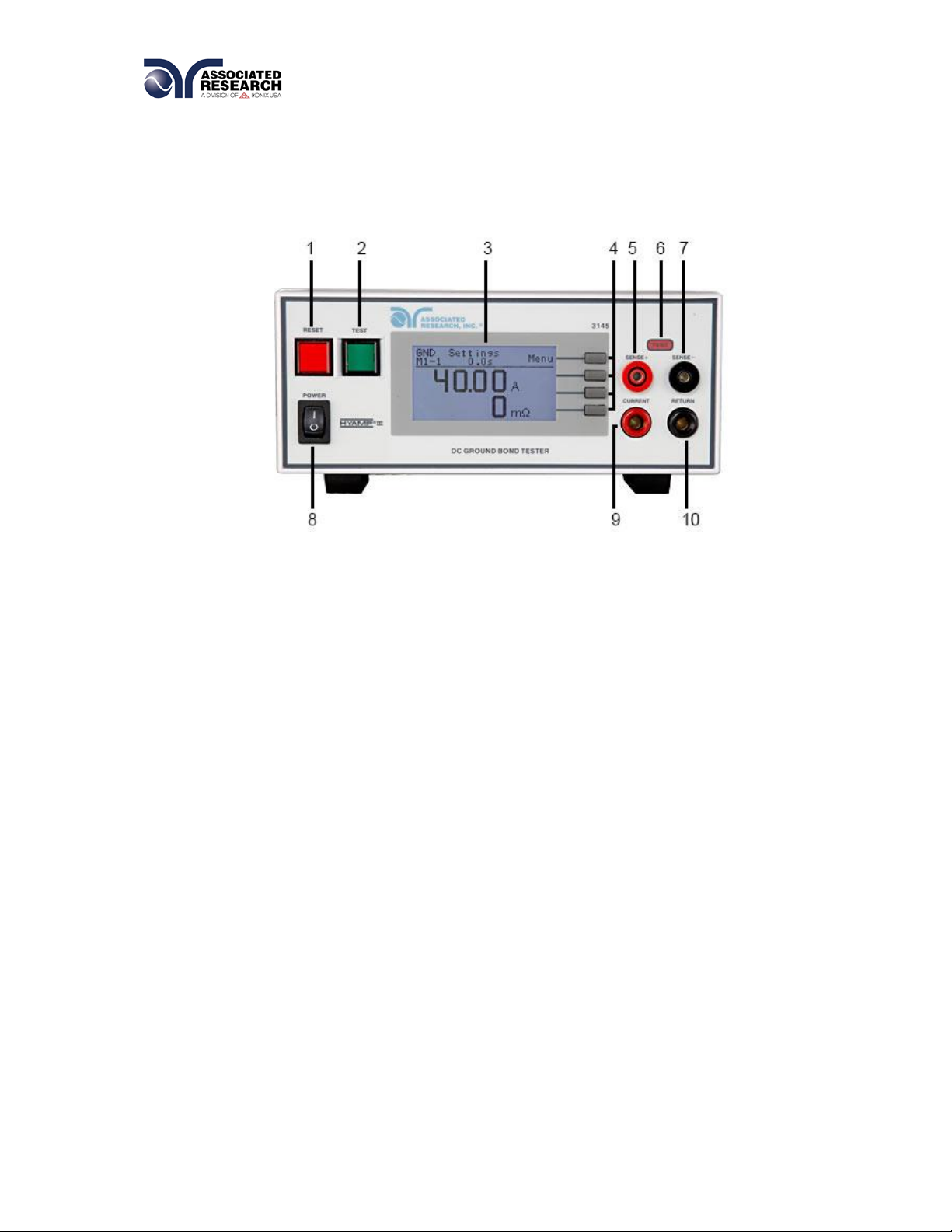
3.2.1. Front Panel Controls for 3145
1. RESET BUTTON: Momentary contact switch used to reset the instrument. If a
failure condition occurs during a test, you will need to reset the system to shut off
the alarm and signal the system that you are aware of a failure condition. The
reset button must be pressed before you can proceed to the next test or change
any of the set-up parameters. This switch also serves as an abort signal to stop
any test in progress controlled by the HYAMP III.
2. TEST BUTTON: Momentary contact switch used to start tests. Press the green
button to activate the test that is set up in the test buffer shown on the display.
3. GRAPHIC LCD: 128 X 64 Monographic LCD.
4. SOFT KEYS: Multifunction parameter selection keys. Keys used to select screens
and change parameters.
5. SENSE+ JACK: Connector used to attach the Current test lead or test fixture to
the instrument. This connector provides a positive Kelvin voltage sensing for the
instrument.
6. TEST LED INDICATOR: This red indicator flashes to warn the operator that
current is present at the output terminal, and a test is in process.

____________________________________________________________________________
18
7. SENSE- JACK: Connector used to attach the Return test lead or test fixture to the
instrument. This connector provides a negative Kelvin voltage sensing for the
instrument.
8. POWER SWITCH: Rocker style power switch with international ON ( ) and OFF
(0) markings.
9. CURRENT OUTPUT JACK: Connector used to attach the Current test lead,
adapter box, or test fixture to the instrument.
10.RETURN OUTPUT JACK: Connector used to attach the Return test lead, adapter
box, or test fixture to the instrument.
3.2.2. Rear Panel Controls for 3145
1. RS-232 CONNECTOR: 9-Pin D subminiature connector for interconnection to RS-
232 Bus interface.
2. FUSE RECEPTACLE: To change the fuse, unplug the power (mains) cord and
turn the fuse receptacle counter-clockwise. The fuse compartment will be
exposed. Please replace the fuse with one of the proper rating.
3. INPUT POWER RECEPTACLE: Standard IEC 320 connector for connection to a
standard NEMA style line power (mains) cord.
4. CHASSIS GROUND (EARTH) TERMINAL: This terminal should be connected to
a good earth ground before operation.
5. THERMAL COOLING FAN: Full time cooling fan.
This manual suits for next models
1
Table of contents
Other IKONIX Test Equipment manuals

IKONIX
IKONIX Associated Research Hypot 3805 User manual

IKONIX
IKONIX ASSOCIATED RESEARCH HypotMAX 7710 Operation manual

IKONIX
IKONIX LVB-2 User manual

IKONIX
IKONIX SCi 260 Series Installation and operating instructions

IKONIX
IKONIX Associated Research HYAMP III Operation manual

IKONIX
IKONIX SCI 290 Series Installation and operating instructions

IKONIX
IKONIX TVB-1 User manual

IKONIX
IKONIX ASSOCIATED RESEARCH HypotMAX 7705 User manual


