iFIT NordicTrack COMMERCIAL 1250 User manual

USER’S MANUAL
Model No. NTL14124.0
Serial No.
Write the serial number in the space
above for reference.
REGISTER YOUR
PRODUCT
MEMBER CARE
Serial Number
Decal
CAUTION
Read all precautions and
instructions in this manual before
using this equipment. Keep this
manual for future reference.
nordictrack.com
To register your product and
activate your warranty today, go
to my.nordictrack.com.
For service at any time, go to
my.iFIT.com or scan the QR code.
Please do not contact the store.
2
WARNING DECAL PLACEMENT . . . . . . . . . . . . . . . . . . . . . . . . . . . . . . . . . . . . . . . . . . . . . . . . . . . . . . . . . . . . . . .2
IMPORTANT PRECAUTIONS..................................................................3
BEFORE YOU BEGIN. . . . . . . . . . . . . . . . . . . . . . . . . . . . . . . . . . . . . . . . . . . . . . . . . . . . . . . . . . . . . . . . . . . . . . . .6
PART IDENTIFICATION CHART. . . . . . . . . . . . . . . . . . . . . . . . . . . . . . . . . . . . . . . . . . . . . . . . . . . . . . . . . . . . . . . .7
ASSEMBLY . . . . . . . . . . . . . . . . . . . . . . . . . . . . . . . . . . . . . . . . . . . . . . . . . . . . . . . . . . . . . . . . . . . . . . . . . . . . . . . .8
HOW TO PLUG IN THE POWER CORD ........................................................17
HOW TO USE THE TREADMILL ..............................................................18
FCC INFORMATION . . . . . . . . . . . . . . . . . . . . . . . . . . . . . . . . . . . . . . . . . . . . . . . . . . . . . . . . . . . . . . . . . . . . . . . .29
HOW TO FOLD AND MOVE THE TREADMILL . . . . . . . . . . . . . . . . . . . . . . . . . . . . . . . . . . . . . . . . . . . . . . . . . . .30
MAINTENANCE AND TROUBLESHOOTING.....................................................31
EXERCISE GUIDELINES ....................................................................34
PART LIST. . . . . . . . . . . . . . . . . . . . . . . . . . . . . . . . . . . . . . . . . . . . . . . . . . . . . . . . . . . . . . . . . . . . . . . . . . . . . . . .38
EXPLODED DRAWING. . . . . . . . . . . . . . . . . . . . . . . . . . . . . . . . . . . . . . . . . . . . . . . . . . . . . . . . . . . . . . . . . . . . . .40
ORDERING REPLACEMENT PARTS. . . . . . . . . . . . . . . . . . . . . . . . . . . . . . . . . . . . . . . . . . . . . . . . . . . Back Cover
LIMITED WARRANTY. . . . . . . . . . . . . . . . . . . . . . . . . . . . . . . . . . . . . . . . . . . . . . . . . . . . . . . . . . . . . . . Back Cover
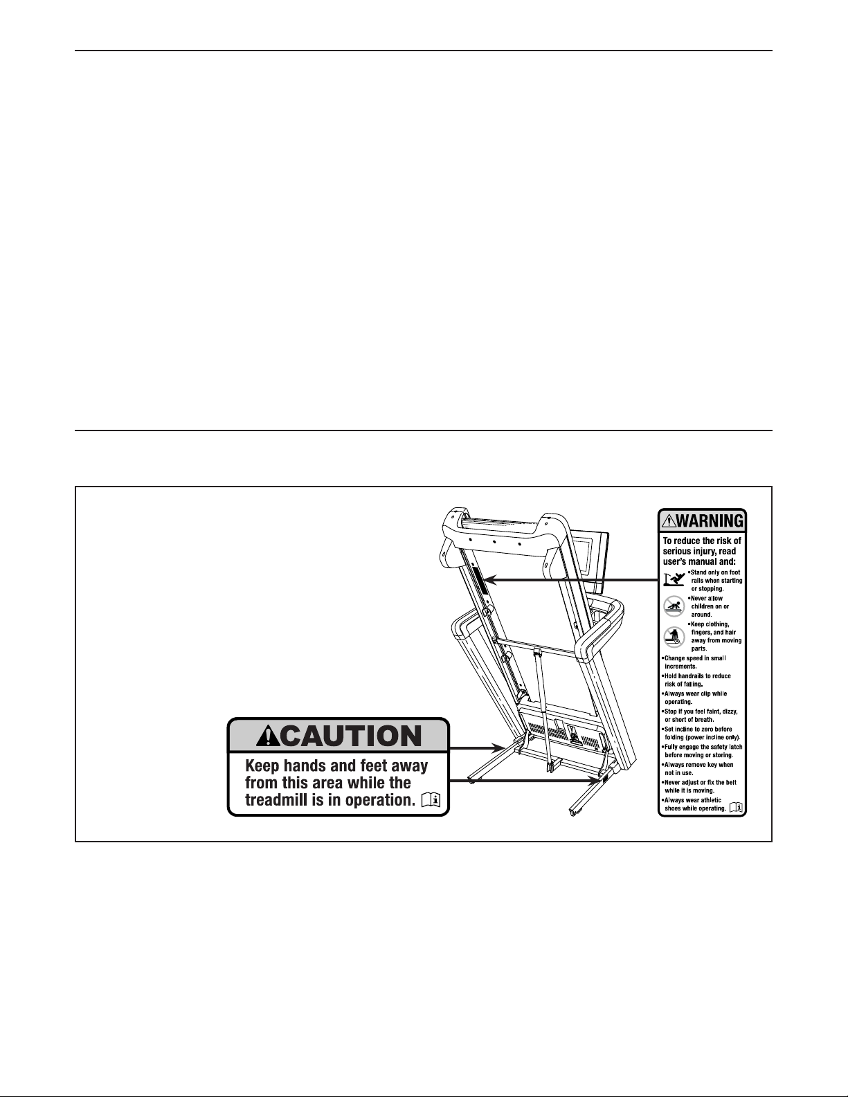
This drawing shows the locations of the warning
decals. If a decal is missing or illegible, see
the front cover of this manual and request a
free replacement decal. Apply the decal in the
location shown. Note: The decals may not be
shown at actual size.
WARNING DECAL PLACEMENT
TABLE OF CONTENTS
NORDICTRACK and IFIT are registered trademarks of iFIT Inc. The Bluetooth®word mark and logos are regis-
tered trademarks of Bluetooth SIG, Inc. and are used under license. Google Maps is a trademark of Google LLC.
Wi-Fi is a registered trademark of Wi-Fi Alliance. WPA and WPA2 are trademarks of Wi-Fi Alliance.

3
1. It is the responsibility of the owner to ensure
that all users of the treadmill are adequately
informed of all warnings and precautions.
2. Keep children under age 16 and pets away
from the treadmill at all times.
3. Consult your health care provider before
beginning any exercise program. This is
especially important for persons over age 35
or persons with pre-existing health problems.
4. Consult your health care provider before
beginning or continuing any exercise
program during pregnancy. Use the treadmill
only as authorized by your health care
provider.
5. The treadmill is not intended for use by
persons with reduced physical, sensory, or
mental capabilities or lack of experience and
knowledge, unless they have been given
supervision or instruction concerning the
use of the treadmill by someone responsible
for their safety.
6. Use the treadmill only as described in this
manual.
7. The treadmill is intended for home use only.
Do not use the treadmill in any commercial,
rental, or institutional setting.
8. Keep the treadmill indoors, away from mois-
ture and dust. Do not put the treadmill in a
garage or covered patio, or near water.
9. Place the treadmill on a level surface, with
at least 8 ft. (2.4 m) of clearance behind it
and 2 ft. (0.6 m) on each side. Do not place
the treadmill on any surface that blocks air
openings. To protect the floor or carpet from
damage, place a mat under the treadmill.
10. Do not operate the treadmill where aerosol
products are used or where oxygen is being
administered.
11. The treadmill should be used only by per-
sons weighing 300 lbs. (135 kg) or less.
12. Never allow more than one person on the
treadmill at a time.
13. Wear appropriate exercise clothes while
using the treadmill. Do not wear loose
clothes that could become caught in the
treadmill. Athletic support clothes are recom-
mended for both men and women. Always
wear athletic shoes. Never use the treadmill
with bare feet, wearing only stockings, or in
sandals.
14. Plug the power cord into a surge suppressor
(not included), and plug the surge suppres-
sor into an appropriate outlet (see page 17).
To avoid overloading the circuit, do not plug
other electrical devices, except for low-power
devices such as cell phone chargers, into
the surge suppressor or into an outlet on the
same circuit.
15. Use only a surge suppressor that meets all of
the specifications described on page 17. To
purchase a surge suppressor, see your local
NORDICTRACK dealer, see the front cover
of this manual, or see your local electronics
store.
16. Failure to use a properly functioning surge
suppressor could result in damage to the
control system of the treadmill. If the control
system is damaged, the walking belt may
slow, accelerate, or stop unexpectedly, which
may result in a fall and serious injury.
17. Keep the power cord away from heated
surfaces.
18. Never move the walking belt while the power
is turned off. Do not operate the treadmill
if the power cord or plug is damaged, or if
the treadmill is not working properly. (See
MAINTENANCE AND TROUBLESHOOTING
on page 31 if the treadmill is not working
properly.)
WARNING: To reduce the risk of burns, fire, electric shock, or injury to persons, read
all important precautions and instructions in this manual and all warnings on your treadmill before
using your treadmill. iFIT assumes no responsibility for personal injury or property damage sus-
tained by or through the use of this product.
IMPORTANT PRECAUTIONS

4
19. Read, understand, and test the emergency
stop procedure before using the treadmill
(see HOW TO TURN ON THE CONSOLE on
page 19). Always wear the clip while using the
treadmill.
20. Be careful when mounting and dismounting
the treadmill. Always stand on the foot rails
when starting or stopping the walking belt.
Always hold the handrails while using the
treadmill.
21. When a person is walking on the treadmill,
the noise level of the treadmill will increase.
22. Keep fingers, hair, and clothing away from
the moving walking belt.
23. The treadmill is capable of high speeds.
Adjust the speed in small increments to
avoid sudden jumps in speed.
24. Never leave the treadmill unattended while
it is running. Always remove the key, press
the power switch into the off position (see
the drawing on page 6 for the location of the
power switch), and unplug the power cord
when the treadmill is not in use.
25. Do not attempt to move the treadmill until
it is properly assembled. (See ASSEMBLY
on page 8 and HOW TO FOLD AND MOVE
THE TREADMILL on page 30.) You must be
able to safely lift 45 lbs. (20 kg) to move the
treadmill.
26. When folding or moving the treadmill, make
sure that the storage latch is holding the
frame securely in the storage position. Do
not operate the treadmill while it is folded.
27. Do not change the incline of the treadmill by
placing objects under the treadmill.
28. Never insert any object into any opening on
the treadmill.
29. Inspect and properly tighten all parts each
time the treadmill is used. Replace any worn
parts immediately. Use only manufacturer-
supplied parts.
30. DANGER: Always unplug the power
cord immediately after use, before clean-
ing the treadmill, and before performing the
maintenance and adjustment procedures
described in this manual. Never remove the
motor hood unless instructed to do so by an
authorized service representative. Servicing
other than the procedures in this manual
should be performed by an authorized ser-
vice representative only.
31. Over exercising may result in serious injury
or death. If you feel faint, if you become short
of breath, or if you experience pain while
exercising, stop immediately and cool down.
SAVE THESE INSTRUCTIONS

5
all
STANDARD SERVICE PLANS
6
Thank you for selecting the new NORDICTRACK®
COMMERCIAL 1250 treadmill. The COMMERCIAL
1250 treadmill provides an impressive selection of fea-
tures designed to make your workouts at home more
effective and enjoyable.
For your benefit, read this manual carefully before
you use the treadmill. If you have questions after
reading this manual, please see the front cover of this
manual. To help us assist you, note the product model
number and serial number before contacting us. The
model number and the location of the serial number
decal are shown on the front cover of this manual.
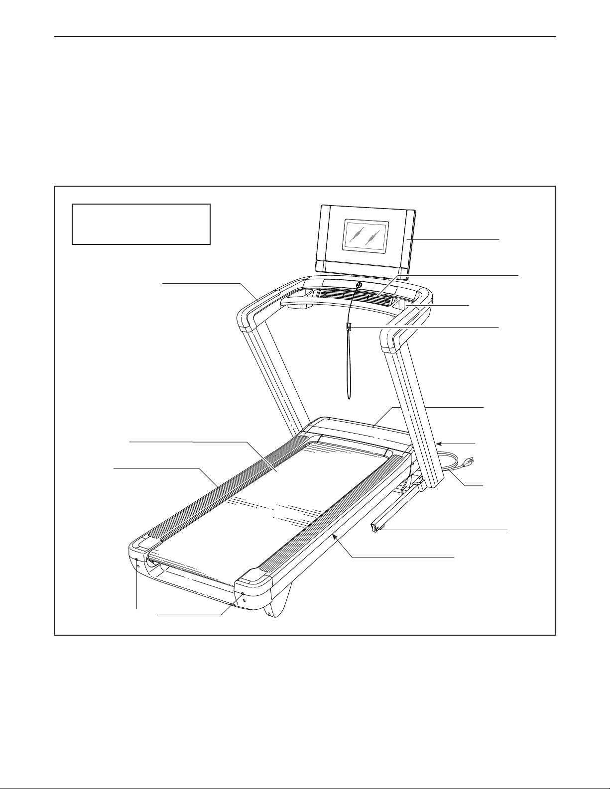
Before reading further, please familiarize yourself with
the parts that are labeled in the drawing below.
BEFORE YOU BEGIN
Handrail
Console
Key/Clip
Accessory Tray
Power Switch
Walking Belt
Motor Hood
Wheel
Foot Rail
Idler Roller Screws
Platform Cushions
Power Cord
Fan
Length: 6 ft. 7 in. (199 cm)
Width: 3 ft. 0 in. (90 cm)
7
PART IDENTIFICATION CHART
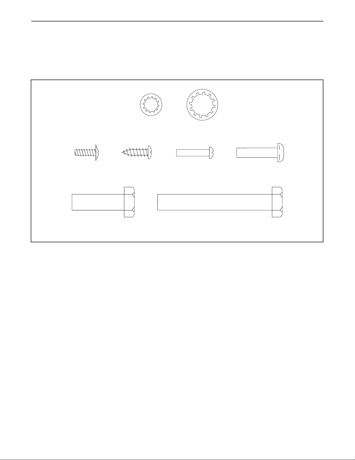
Use the drawings below to identify small parts used for assembly. The number in parentheses below each draw-
ing is the key number of the part, from the PART LIST near the end of this manual. The number following the key
number is the quantity used for assembly. Note: If a part is not in the hardware kit, check to see whether it is
preattached. Extra parts may be included.
3/8" Star
Washer (8)–12
5/16" Star
Washer (5)–2
3/8" x 2 3/4" Screw (40)–4
3/8" x 1 1/4"
Screw (1)–8
Ground
Screw (3)–1
M4 x 20mm
Screw (4)–2
M6 x 25mm
Screw (6)–4
#8 x 5/8"
Screw (132)–1
8
ASSEMBLY
1
1. Go to my.nordictrack.com and register your
product.
• documents your ownership
• activates your warranty
• ensures priority customer support if assistance
is ever needed
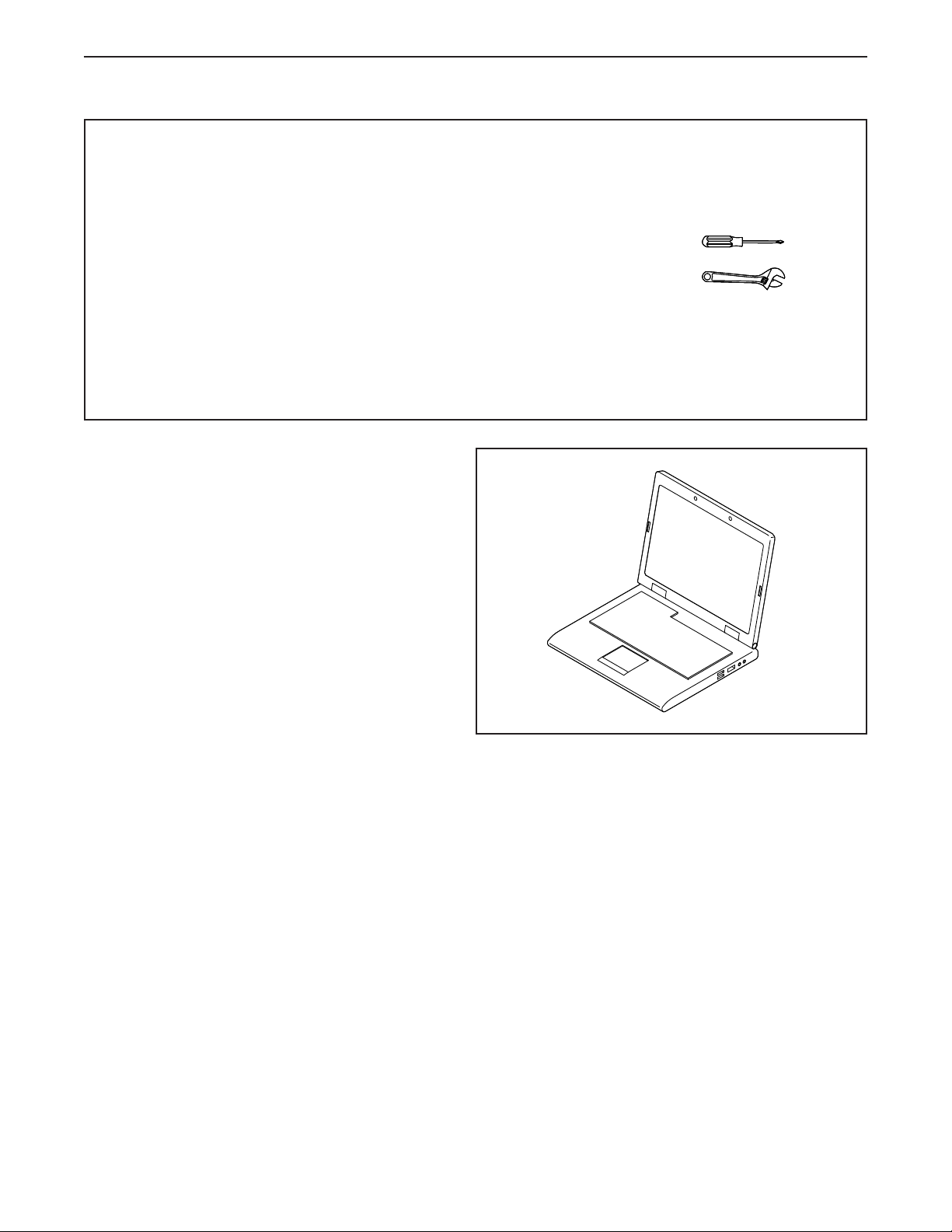
• Assembly requires two persons.
• Place all parts in a cleared area and remove the
packing materials. Do not dispose of the packing
materials until you nish all assembly steps.
• After shipping, there may be an oily substance
on the exterior of the treadmill. This is normal. If
there is an oily substance on the treadmill, wipe
it off with a soft cloth and a mild, non-abrasive
cleaner.
• Left parts are marked “L” or “Left” and right parts
are marked “R” or “Right.”
• To identify small parts, see page 7.
• Assembly requires the included tools and the
following tools:
one Phillips screwdriver
one adjustable wrench
Note: One or more of the included tools may be
needed to make adjustments in the future. To
avoid damaging parts, do not use power tools for
assembly or adjustment.
9
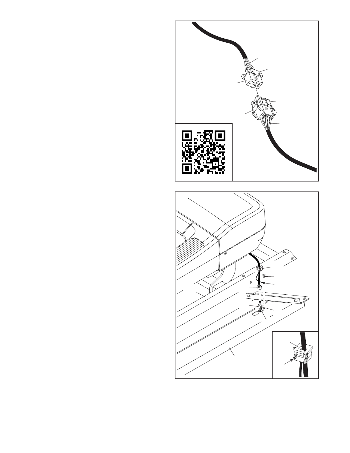
2. IMPORTANT: You will connect wires in one or
more of the following steps. For your tread-
mill to function properly, connect the wires as
described below. Note: The actual wires may
look different from the wires shown.
First, firmly push the wires (V) into each connec-
tor (W, X) to make sure that the wires are fully
seated.
Next, turn the wires so that the latch (Y) on one
connector (W) is on the same side as the catch
(Z) on the other connector (X). (Note: If there
are red dots on the connectors, turn the wires so
that the red dots are on the same side). Then,
slide the connectors together; the connectors
should slide together easily and snap into
place with an audible click.
Then, pull on the connectors (W, X) to make
sure that they are connected; do not pull on the
wires (V). To see a video about connecting
wires, scan the QR code or go to my.iFIT.com.
V
W
X
Y
Z
V
2
3. Make sure that the power cord is unplugged.
Identify the Right Upright (94), and lay it near the
Upright Base (101) as shown.
Next, connect the Belly Pan Wire (80) to the
Upright Wire (92) in the Right Upright (94). For
your treadmill to function properly, make sure
to connect the wires as described in step 2.
Next, insert the Wires (80, 92) into the square
hole (A) in the Right Upright (94), and then press
the Grommet (81) into the square hole. See the
inset drawing. To make insertion easier, insert
the ear (P) on the Grommet into the square hole
first.
Then, remove and discard the indicated screw
(B), and attach the ground wire (C) to the Right
Upright (94) with a Ground Screw (3).
3
C
80
81
94
92
B
A
101
P
81
3
10
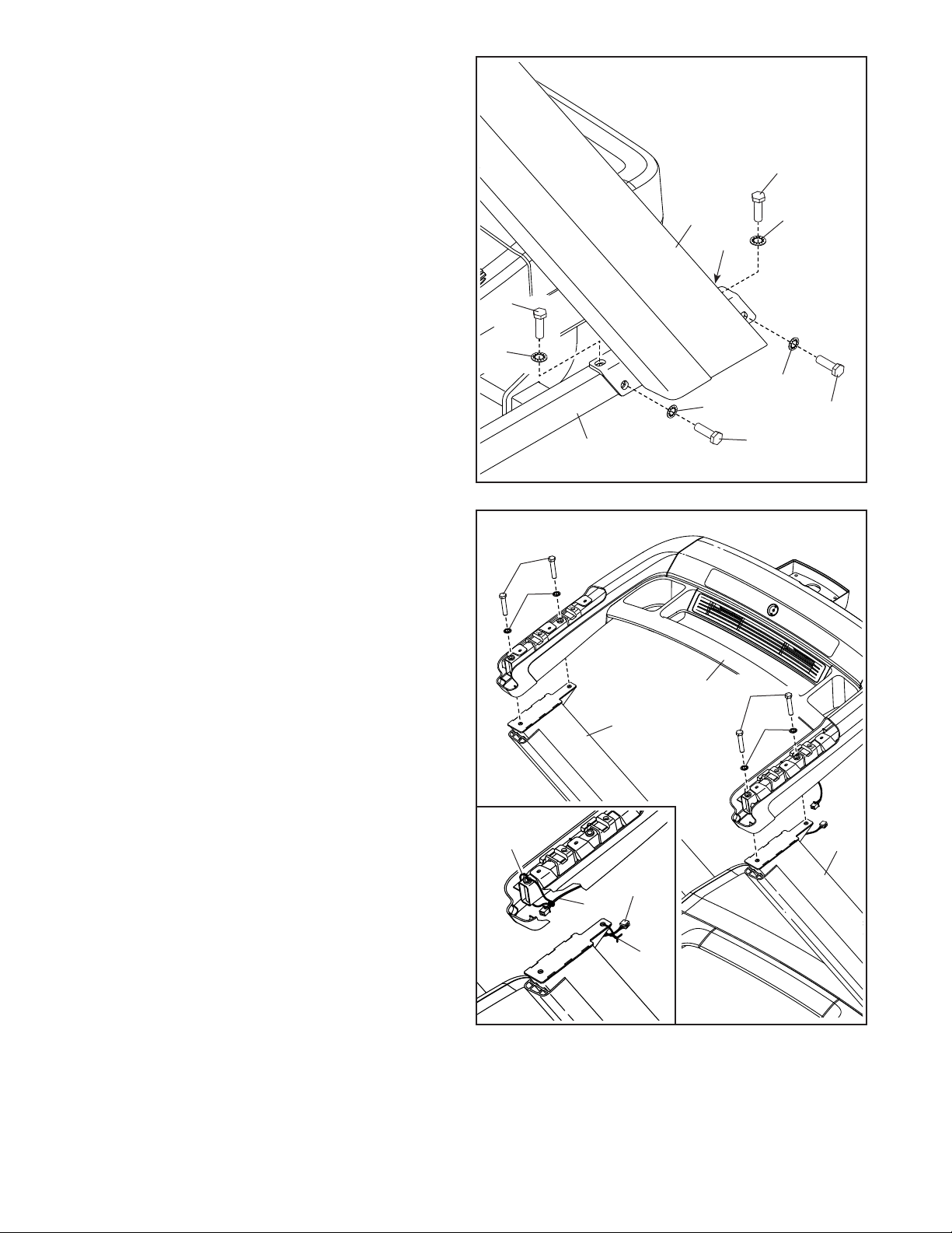
4. Do not to pinch the Belly Pan Wire (80)
during this step. Have a second person hold
the Right Upright (94) against the Upright Base
(101).
Insert two 3/8" x 1 1/4" Screws (1) with two 3/8"
Star Washers (8) into the top of the bracket on
the Right Upright (94), and partially tighten the
Screws into the Upright Base (101); do not fully
tighten the Screws yet.
Finish attaching the Right Upright (94) with
two additional 3/8" x 1 1/4" Screws (1) and two
additional 3/8" Star Washers (8); do not fully
tighten the Screws yet.
Attach the Left Upright (not shown) in the
same way. Note: There is not a wire on the left
side.
4
101
94
1
1
1
8
80
8
8
8
1
5. Do not pinch the Wires (91, 92) during this
step. Have a second person hold the handrail
assembly (E) near the Left and Right Uprights
(93, 94) as shown.
See the inset drawing. Remove the two ties (D)
securing the Handrail Wire (91) and the Upright
Wire (92).
Next, have the second person hold the handrail
assembly (E) on the Left and Right Uprights
(93, 94). Attach the handrail assembly with four
3/8" x 2 3/4" Screws (40) and four 3/8" Star
Washers (8); start all four Screws, and then
tighten them.
5
E
40
8
94
8
93
40
91
92
D
D
11
6
91
92
94
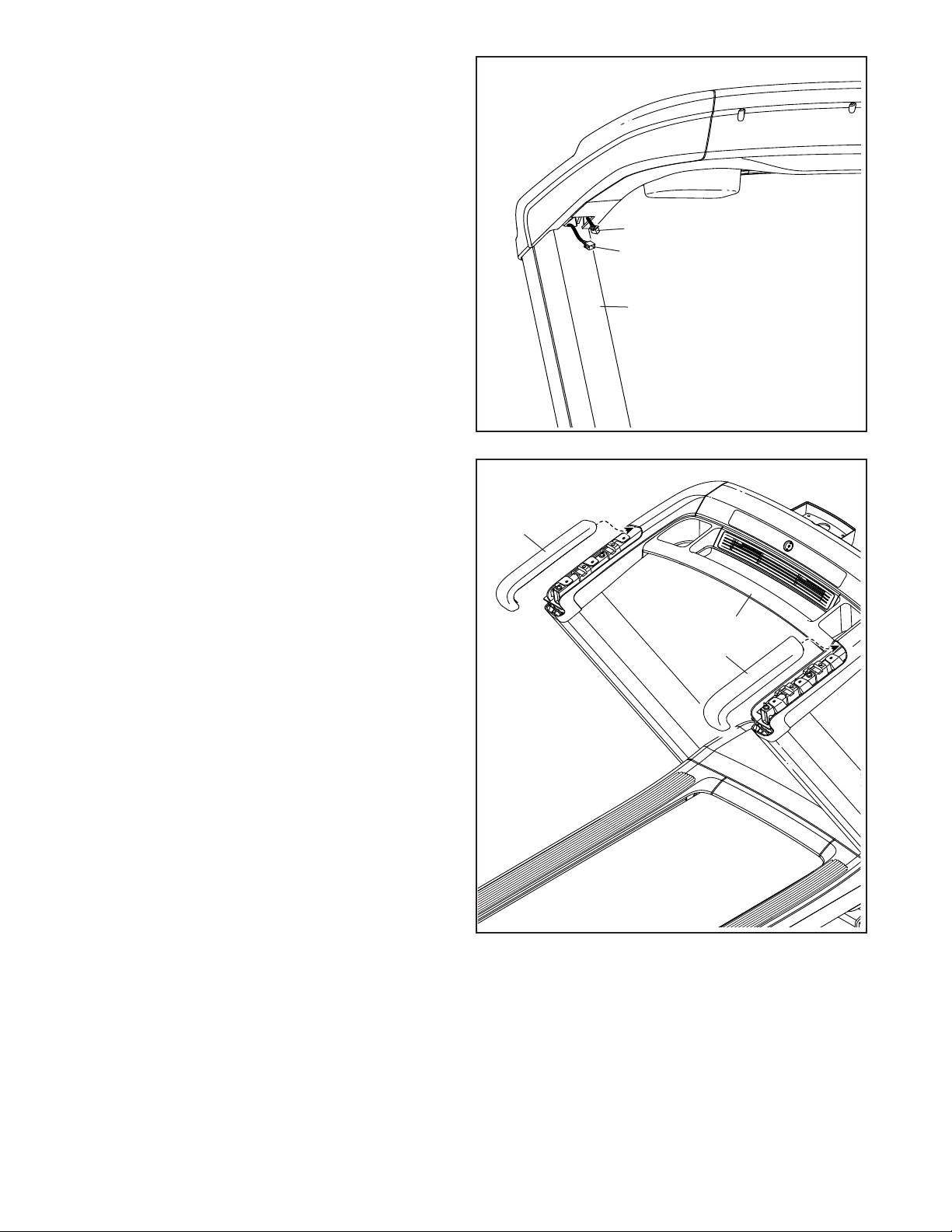
6. Connect the Handrail Wire (91) to the Upright
Wire (92). For your treadmill to function
properly, make sure to connect the wires as
described in step 2. Then, insert the wires into
the Right Upright (94).
7
7. Identify the Right Handrail Cover (84). Insert the
front edge of the Right Handrail Cover into the
top of the handrail assembly (E) on the right side
of the treadmill as shown. Then, press down on
the top of the Right Handrail Cover until it snaps
into place.
Attach the Left Handrail Cover (83) to the left
side of the handrail assembly (E) in the same
way. E
83
84
12
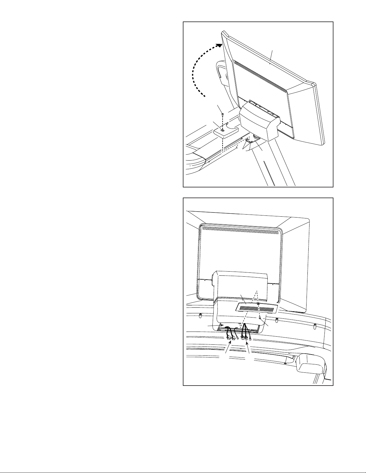
8F
E
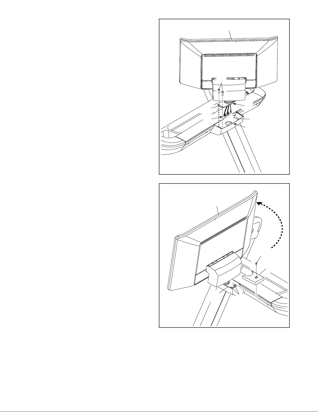
8. Do not pinch the wires (G) during this
step. Have a second person hold the console
assembly (F) near the handrail assembly (E).
IMPORTANT: Make sure that the console
assembly is properly oriented so that the
curved edge (H) of the Console Pivot Bracket
(117) faces the front (I) of the handrail
assembly.
Insert the wires (G) into the round hole in the
handrail assembly (E) as you set the console
assembly (F) on the handrail assembly.
Attach the console assembly (F) with two
M6 x 25mm Screws (6); do not fully tighten the
Screws yet.
I
6
9
9. Rotate the console assembly (F) so that it
faces the opposite direction. Tighten two
M6 x 25mm Screws (6) into the Console Pivot
Bracket (117); start both Screws, and then
firmly tighten them.
Next, identify the Left Pivot Cover (115). Attach
the Left Pivot Cover to the Console Pivot Bracket
(117) with an M4 x 20mm Screw (4); do not
overtighten the Screw.
4
117
115
F
6
117
G
H
13
10
10. Rotate the console assembly (F) back to
its original position. Firmly tighten the two
M6 x 25mm Screws (6) that you attached in
step 8.
Next, identify the Right Pivot Cover (116). Attach
the Right Pivot Cover to the Console Pivot
Bracket (117) with an M4 x 20mm Screw (4); do
not overtighten the Screw.
4
117
116
F
11
118
11. Do not pinch the wires (J, K) during this step.
Connect the indicated wires (J, K). For your
treadmill to function properly, make sure to
connect the wires as described in step 2.
Next, position the wires (J, K) inside of the open-
ing in the handrail assembly (E). Then, insert
the front edge of the Access Panel (118) into the
opening in the handrail assembly, and attach the
Access Panel with a #8 x 5/8" Screw (132): do
not overtighten the Screw.
JK
E132
6
14
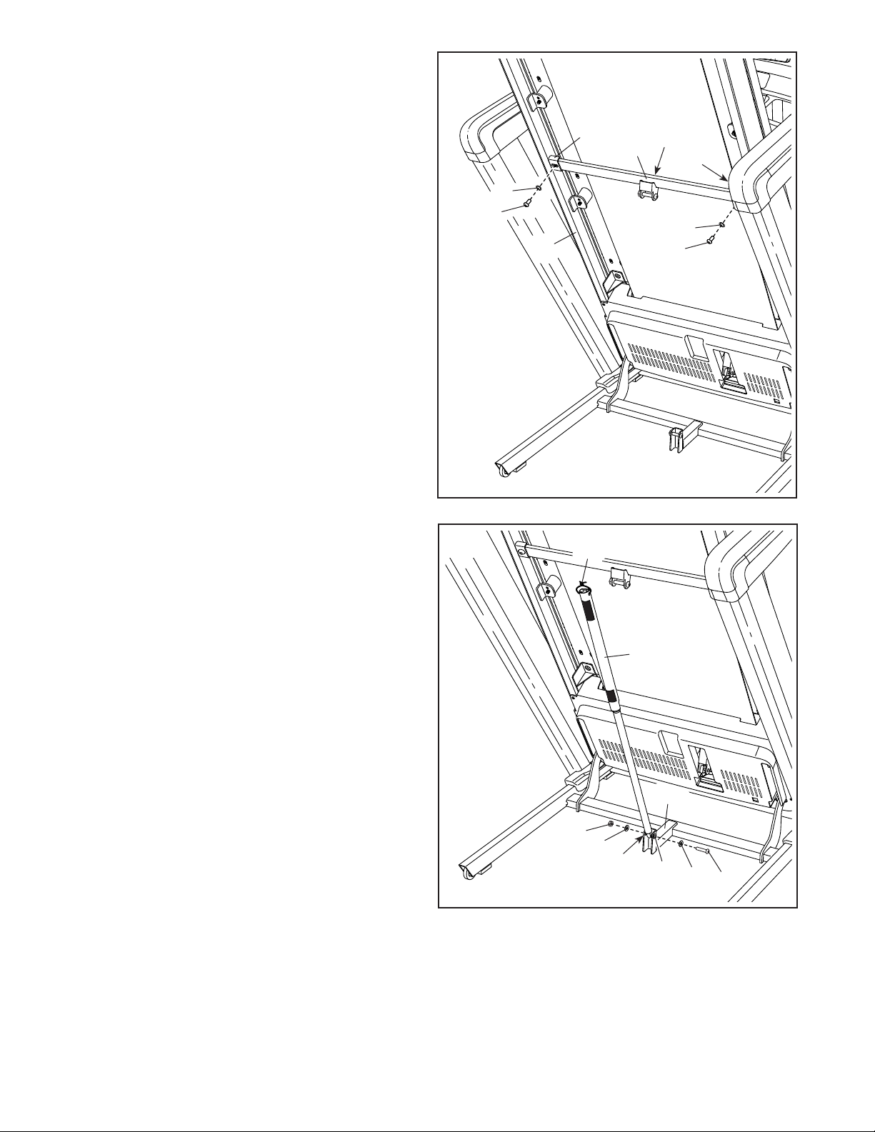
12. Raise the Frame (66) to the position shown.
IMPORTANT: Have a second person hold the
Frame until step 14 is completed.
Remove the two 5/16" x 3/4" Screws (9) from the
Latch Crossbar (62). Note: The Latch Crossbar
is not preattached to the treadmill.
Next, orient the Latch Crossbar (62) as shown.
Make sure that the “This side toward belt”
sticker (L) is facing the treadmill. Attach the
Latch Crossbar to the brackets (M) on the Frame
(66) with the two 5/16" x 3/4" Screws (9) that you
just removed and two 5/16" Star Washers (5).
62 L
12
M
M
5
9
65
13 N
5
9
13. Remove the 5/16" Nut (12), the two 3/8" Thrust
Washers (37), and the 5/16" x 1 3/4" Bolt (10)
from the bracket on the Upright Base (101).
Note: If one of the 5/16" Bushings (130)
comes out, reinsert it.
Next, orient the Storage Latch (65) as shown.
Attach the lower end of the Storage Latch (65)
to the bracket on the Upright Base (101) with
the 5/16" x 1 3/4" Bolt (10), the two 3/8" Thrust
Washers (37), and the 5/16" Nut (12).
Then, raise the Storage Latch (65) to a vertical
position, and remove the tie (N).
10
37
37
12
130
101
130
66

15
14. Remove the 5/16" Nut (12) and the 5/16" x
2 1/4" Bolt (11) from the bracket on the Latch
Crossbar (62).
Next, align the upper end of the Storage Latch
(65) with the bracket on the Latch Crossbar (62),
and insert the 5/16" x 2 1/4" Bolt (11) through the
bracket and the Storage Latch. This will push a
spacer (O) out of the Storage Latch; discard
the spacer. Note: If one of the 5/16" Bushings
(130) comes out, reinsert it.
Next, tighten the 5/16" Nut (12) onto the
5/16" x 2 1/4" Bolt (11). Do not overtighten the
Nut; the Storage Latch (65) must be able to
pivot.
Then, lower the Frame (66) (see HOW TO
LOWER THE TREADMILL FOR USE on
page 30).
62
11
12 O
65
14
15. Firmly tighten the four 3/8" x 1 1/4" Screws (1) in
the Right Upright (94).
Repeat this step on the left side of the
treadmill.
15
94
1
1
1
1
1
1
130
66
16
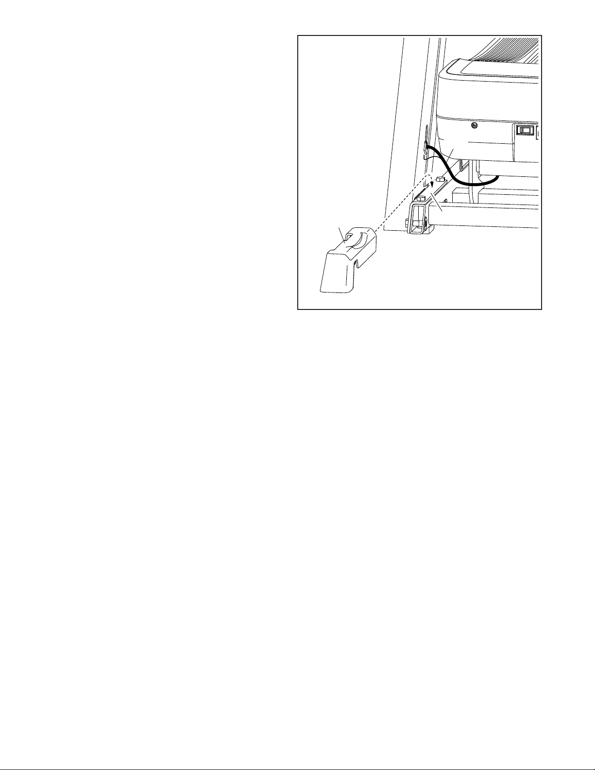
16. Identify the Right Base Cover (98). Slide the
Right Base Cover under the Belly Pan Wire (80)
and onto the Upright Base (101). Make sure
that the Right Base Cover is under the Belly
Pan Wire.
Repeat this step on the left side of the tread-
mill with the Left Base Cover (not shown).
Note: There is not a wire on the left side.
16
80
98
17. Make sure that all parts are properly tightened before you use the treadmill. If there are sheets of plastic
on the treadmill decals, remove the plastic. To protect the floor or carpet, place a mat under the treadmill. To
avoid damage to the console, keep the treadmill out of direct sunlight. Keep the included tools in a secure
place; one or more of the tools may be needed to make adjustments to the treadmill in the future. Note: Extra
hardware may be included.
101
17
HOW TO PLUG IN THE POWER CORD
USE A SURGE SUPPRESSOR
Your treadmill, like other electronic equipment, can be
damaged by sudden voltage changes in your home’s
power. Voltage surges, spikes, and noise interference
can result from weather conditions or from other appli-
ances being turned on or off. To decrease the risk of
damaging the treadmill, always use a surge sup-
pressor (A) with the treadmill. To purchase a surge
suppressor, see precaution 15 on page 3.
Use only a surge suppressor (A) that is UL 1449 listed
as a transient voltage surge suppressor (TVSS). The
surge suppressor must have a UL suppressed volt-
age rating of 400 volts or less and a minimum surge
dissipation of 450 joules. The surge suppressor must
also be electrically rated for 120 volts AC and 15
amps. There must be a monitoring light on the surge
suppressor to indicate whether it is functioning prop-
erly. Failure to use a properly functioning surge
suppressor could result in damage to the control
system of the treadmill and serious injury to users.
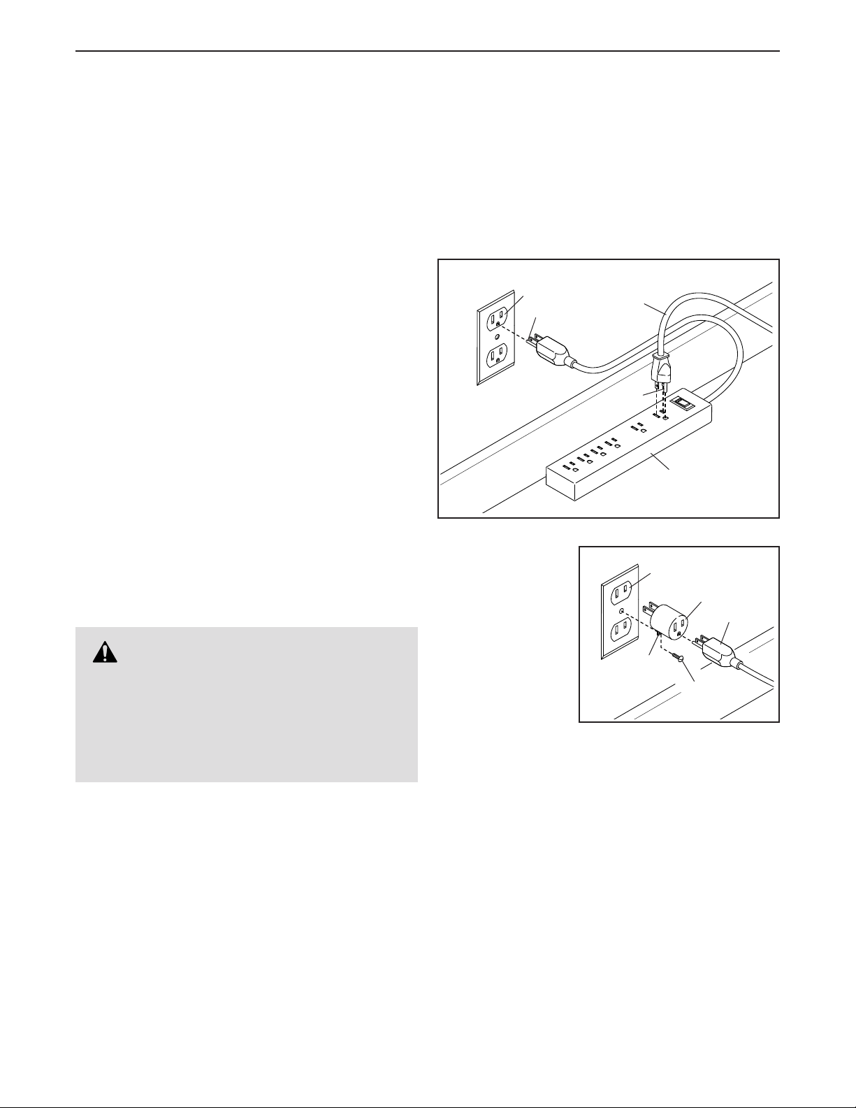
PLUG IN THE POWER CORD
The treadmill must be grounded. If it should malfunc-
tion or break down, grounding provides a path of least
resistance for electric current to reduce the risk of elec-
tric shock. The treadmill power cord (B) has a plug with
a grounding pin (C) (see drawing 1 on this page).
Plug the power cord (B) into a surge suppressor
(A), and plug the surge suppressor into an appropri-
ate outlet (D) that is properly installed and grounded
in accordance with all local codes and ordinances.
The outlet must be on a nominal 120-volt circuit
capable of carrying 15 or more amps. To avoid
overloading the circuit, do not plug other electrical
devices, except for low-power devices such as cell
phone chargers, into the surge suppressor or into
an outlet on the same circuit. IMPORTANT: If the
treadmill is connected to an AFCI-equipped outlet
and your circuit breaker trips repeatedly when the
treadmill is used, see the front cover of this manual
to purchase an arc filter.
A temporary
adapter (E) may
be used to con-
nect the surge
suppressor (A) to
a 2-pole recep-
tacle (F) if a
properly grounded
outlet is not
available.
The lug (G) or wire extending from the adapter must
be connected with a metal screw (H) to a permanent
ground such as a properly grounded outlet box cover.
Some 2-pole receptacle outlet box covers are not
grounded. Before using an adapter, contact a quali-
fied electrician to determine whether the outlet box
cover is grounded. The temporary adapter should
be used only until a properly grounded outlet can
be installed by a qualified electrician.
DANGER: Improper connection of
the power cord increases the risk of electric
shock. Do not modify the plug—if it will not fit
an outlet, have a proper outlet installed by a
qualified electrician. If you are unsure whether
the treadmill is properly grounded, contact a
qualified electrician.
1
A
C
D
C
B
2
E
F
G
A
H

18
ETNT14124
FEATURES OF THE CONSOLE
The advanced console offers a selection of features
designed to make your workouts more effective and
enjoyable.
When you use the manual mode of the console, you
can change the speed and incline of the treadmill with
a touch of a button. As you exercise, the console will
display instant exercise feedback.
You can even monitor your heart rate when you use
a compatible heart rate monitor. To purchase a
compatible heart rate monitor, see page 29.
The console also features wireless technology that
enables the console to connect to iFIT®. With iFIT, you
can choose from a rotating selection of featured work-
outs that automatically control the speed and incline of
the treadmill as iFIT trainers guide you through immer-
sive exercise sessions.
With an iFIT subscription, you can access a large and
varied library of thousands of on-demand destination
and studio workouts, create your own workouts, track
your workout results, and access many other features.
To turn on and turn off the console, see page 19. To
learn how to use the touch screen, see page 19. To
set up the console, see page 20.
HOW TO USE THE TREADMILL

19
HOW TO TURN ON THE CONSOLE
IMPORTANT: If the treadmill has been exposed to
cold temperatures, allow it to warm to room tem-
perature before you turn on the console. If you do
not do this, you may damage the console displays
or other electrical components.
Plug in the power cord (see
page 17). Next, locate the
power switch on the treadmill
frame near the power cord.
Press the power switch into
the reset position (A).
Next, stand on the
foot rails of the
treadmill. Locate
the clip (B) attached
to the key (C), and
slide the clip securely
onto the waistband
of your clothes.
Then, insert the key
into the console.
Note: It may take
up to a few minutes for the console to be ready for
use. IMPORTANT: In an emergency, the key can be
pulled from the console, causing the walking belt
to slow to a stop. Test the clip by carefully taking
a few steps backward; if the key is not pulled from
the console, adjust the position of the clip.
Note: The console can display speed and distance
in either miles or kilometers. To find which unit of
measurement is selected, see HOW TO CHANGE
CONSOLE SETTINGS on page 26.
HOW TO TURN OFF THE CONSOLE
When you are finished using the treadmill, first remove
the key from the console and put it in a secure place.
Then, press the power switch into the off position and
unplug the power cord. IMPORTANT: If you do not do
this, the electrical components of the treadmill may
wear prematurely.
IMPORTANT: Before you fold the treadmill, make
sure that the incline is adjusted to the appropri-
ate level (see HOW TO FOLD AND MOVE THE
TREADMILL on page 30).
HOW TO USE THE TOUCH SCREEN
The console features a tablet with a full-color touch
screen. The following information will help you become
familiar with the tablet’s advanced technology:
• The console functions similarly to other tablets. You
can slide or ick your nger against the screen to
move certain images on the screen, such as the
displays in a workout.
• The screen is not pressure sensitive. You do not
need to press hard on the screen.
• To type information into a text box, rst touch the text
box to view the keyboard. To use numbers or other
characters on the keyboard, touch ?123. To view
more characters, touch ~[<. Touch ?123 again to
return to the number keyboard. To return to the letter
keyboard, touch ABC. To use a capital character,
touch the shift button (upward-facing arrow symbol).
To use multiple capital characters, touch the shift
button again. To return to the lowercase keyboard,
touch the shift button a third time. To clear the last
character, touch the clear button (backward-facing
arrow with an X symbol).
A
B
C

20
HOW TO SET UP THE CONSOLE
Before you use the treadmill for the first time, set up
the console.
1. Connect to your wireless network.
To use iFIT workouts and to use several other
features of the console, the console must be con-
nected to a wireless network. Follow the prompts
on the screen to connect the console to your wire-
less network.
2. Customize settings.
Follow the prompts on the screen to set the desired
unit of measurement and your time zone.
Note: To change these settings later, see HOW TO
CHANGE CONSOLE SETTINGS on page 26.
3. Log into or create an iFIT account.
Follow the prompts on the screen to log into your
iFIT account or to create an iFIT account.
4. Check for firmware updates.
Touch the menu button (three horizontal lines sym-
bol), touch Settings, touch Maintenance, and then
touch Update. The console will check for firmware
updates. For more information, see step 6 on
page 27.
Firmware updates are always designed to
improve your exercise experience. As a result,
new settings and features may not be described
in this manual. Also, some settings and features
described in this manual may no longer be
enabled. Take time to explore the console to learn
how new settings and features work.
5. Calibrate the incline system.
Touch the menu button (three horizontal lines
symbol), touch Settings, touch Maintenance, and
then touch Calibrate Incline and follow the prompts
on the screen. The frame will rise and lower as it
calibrates. For more information, see step 7 on
page 27.
The console is now ready for you to begin working out.
The following pages explain the workouts and other
features that the console offers.
To use the manual mode, see page 21. To use a
featured workout, see page 22. To create a draw-
your-own-map workout, see page 24. To use an iFIT
workout, see page 25.
To change console settings, see page 26. To
connect to a wireless network, see page 28.
IMPORTANT: If there are sheets of plastic on the
console, remove the plastic. To prevent damage
to the walking platform, wear clean athletic shoes
while using the treadmill. The first time you use
the treadmill, observe the alignment of the walking
belt, and center the walking belt if necessary (see
page 32).
This manual suits for next models
1
Table of contents
Other iFIT Treadmill manuals


Popular Treadmill manuals by other brands


Smooth Fitness
Smooth Fitness EVO 3i user manual

NordicTrack
NordicTrack NETL81810.0 user manual

Schwinn
Schwinn 830/Journey 8.0 Assembly manual / owner's manual

Keys Fitness
Keys Fitness HealthTrainer HT-740T owner's manual

Spirit
Spirit XT8 Service manual

NordicTrack
NordicTrack T 14.0 Treadmill Manuel de l'utilisateur