Ethernet switch EC2095
4
2 Safety instructions
2.1 General
These instructions contain texts and figures concerning the correct handling of the
device and must be read before installation or use.
Observe the operating instructions. Non-observance of the instructions, operati-
on which is not in accordance with use as prescribed below, wrong installation or
incorrect handling can seriously affect the safety of operators and machinery.
2.2 Target group
These instructions are intended for authorised persons according to the EMC and
low-voltage directives. The device must only be installed, connected and put into
operation by a qualified electrician.
2.3 Electrical connection
Disconnect the unit externally before handling it. If necessary, also disconnect any
independently supplied output load circuits.
If the device is not supplied by the mobile on-board system (12/24 V battery
operation), it must be ensured that the external voltage is generated and supplied
according to the criteria for safety extra-low voltage (SELV) as this voltage is
supplied without further measures to the connected controller, the sensors and the
actuators.
The wiring of all signals in connection with the SELV circuit of the device must also
comply with the SELV criteria (safety extra-low voltage, safe electrical isolation
from other electric circuits).
If the supplied SELV voltage is externally grounded (SELV becomes PELV), the
responsibility lies with the user and the respective national installation regulations
must be complied with. All statements in this document refer to the device the
SELV voltage of which is not grounded.
The connection terminals may only be supplied with the signals indicated in the
technical data and/or on the device label and only the approved accessories of ifm
electronic may be connected.
2.4 Tampering with the device
In case of malfunction or uncertainties please contact the manufacturer. Tampering
with the device can seriously affect the safety of operators and machinery. It is not
permitted and leads to the exclusion of any liability and warranty claims.
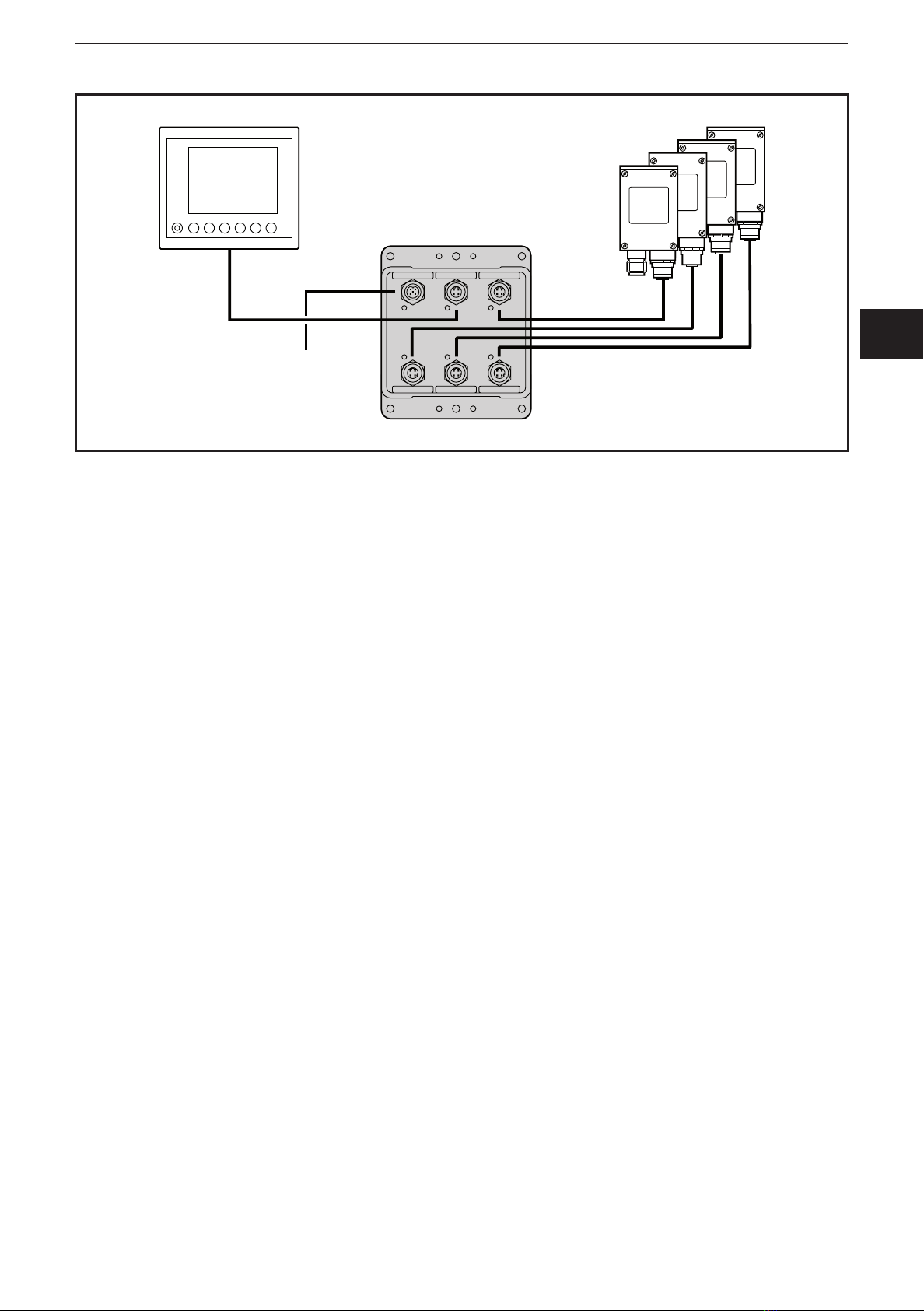
3 Functions and features
The device is used for networking up to 5 Ethernet devices.
It enables, for example, connection of a process and dialogue monitor PDM 360
with up to 4 Ethernet cameras.