IFM Electronic Ecomat100 EC2100 Manual

Short instructions
CAN BusTester
Mobile device for the analysis
of CAN networks
EC2100
7390922 / 00 05 / 2012
UK

CAN BusTester EC2100
2
Contents
1 Preliminary note � � � � � � � � � � � � � � � � � � � � � � � � � � � � � � � � � � � � � � � � � � � � � � � � � 4
1�1 Symbols used� � � � � � � � � � � � � � � � � � � � � � � � � � � � � � � � � � � � � � � � � � � � � � � 4
1�2 Warning signs used � � � � � � � � � � � � � � � � � � � � � � � � � � � � � � � � � � � � � � � � � � 4
2 Safety instructions � � � � � � � � � � � � � � � � � � � � � � � � � � � � � � � � � � � � � � � � � � � � � � � 4
3 Functions and features � � � � � � � � � � � � � � � � � � � � � � � � � � � � � � � � � � � � � � � � � � � � 5
3�1 Features at a glance� � � � � � � � � � � � � � � � � � � � � � � � � � � � � � � � � � � � � � � � � � 5
3�2 Help and additional information � � � � � � � � � � � � � � � � � � � � � � � � � � � � � � � � � 5
4 Installation� � � � � � � � � � � � � � � � � � � � � � � � � � � � � � � � � � � � � � � � � � � � � � � � � � � � � � 5
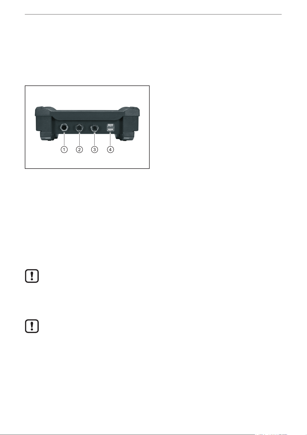
5 Electrical connection� � � � � � � � � � � � � � � � � � � � � � � � � � � � � � � � � � � � � � � � � � � � � � 6
5�1 General electrical connection � � � � � � � � � � � � � � � � � � � � � � � � � � � � � � � � � � � 6
5�2 Operating voltage � � � � � � � � � � � � � � � � � � � � � � � � � � � � � � � � � � � � � � � � � � � � 6
5�2�1 Battery charging� � � � � � � � � � � � � � � � � � � � � � � � � � � � � � � � � � � � � � � � � 6
5�2�2 Battery life � � � � � � � � � � � � � � � � � � � � � � � � � � � � � � � � � � � � � � � � � � � � � 6
5�3 CAN interface (terminating resistor) � � � � � � � � � � � � � � � � � � � � � � � � � � � � � � 6
5�4 Ethernet interface � � � � � � � � � � � � � � � � � � � � � � � � � � � � � � � � � � � � � � � � � � � 6
5�5 USB interfaces � � � � � � � � � � � � � � � � � � � � � � � � � � � � � � � � � � � � � � � � � � � � � � 7
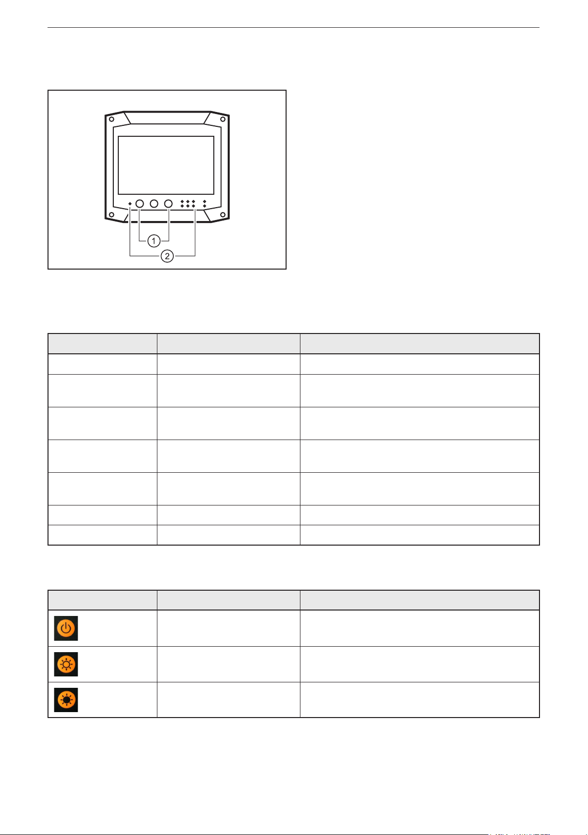
6 Operating and display elements � � � � � � � � � � � � � � � � � � � � � � � � � � � � � � � � � � � � � 8
6�1 Display � � � � � � � � � � � � � � � � � � � � � � � � � � � � � � � � � � � � � � � � � � � � � � � � � � � � 8
6�2 Operating elements � � � � � � � � � � � � � � � � � � � � � � � � � � � � � � � � � � � � � � � � � � 8
7 Setup � � � � � � � � � � � � � � � � � � � � � � � � � � � � � � � � � � � � � � � � � � � � � � � � � � � � � � � � � 9
7�1 General notes� � � � � � � � � � � � � � � � � � � � � � � � � � � � � � � � � � � � � � � � � � � � � � � 9
7�1�1 Notes on the touch screen � � � � � � � � � � � � � � � � � � � � � � � � � � � � � � � � � 9
7�2 Switch on the device � � � � � � � � � � � � � � � � � � � � � � � � � � � � � � � � � � � � � � � � 10
7�3 Switch off the device � � � � � � � � � � � � � � � � � � � � � � � � � � � � � � � � � � � � � � � � 10
7�3�1 Switch off via the ON/OFF key� � � � � � � � � � � � � � � � � � � � � � � � � � � � � 10
7�3�2 Switch off via softkey � � � � � � � � � � � � � � � � � � � � � � � � � � � � � � � � � � � � 10
7�4 Set the screen contrast � � � � � � � � � � � � � � � � � � � � � � � � � � � � � � � � � � � � � � �11
7�5 Switch the screen on/off � � � � � � � � � � � � � � � � � � � � � � � � � � � � � � � � � � � � � � �11
7�6 Language selection � � � � � � � � � � � � � � � � � � � � � � � � � � � � � � � � � � � � � � � � � �11
8 Operation � � � � � � � � � � � � � � � � � � � � � � � � � � � � � � � � � � � � � � � � � � � � � � � � � � � � � 12
8�1 User interface � � � � � � � � � � � � � � � � � � � � � � � � � � � � � � � � � � � � � � � � � � � � � � 12
8�1�1 Main menu � � � � � � � � � � � � � � � � � � � � � � � � � � � � � � � � � � � � � � � � � � � � 12
8�1�2 Configuration menu � � � � � � � � � � � � � � � � � � � � � � � � � � � � � � � � � � � � � 13
8�1�3 Status Line � � � � � � � � � � � � � � � � � � � � � � � � � � � � � � � � � � � � � � � � � � � � 13
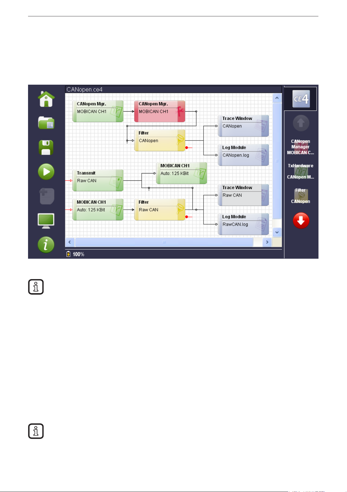
8�2 The most important function elements of the measuring setup � � � � � � � � 14
8�2�1 CANopen Manager (hardware) � � � � � � � � � � � � � � � � � � � � � � � � � � � � 14
8�2�2 CANopen Manager � � � � � � � � � � � � � � � � � � � � � � � � � � � � � � � � � � � � � 16
8�2�3 Trace panels (RawCAN and CANopen)� � � � � � � � � � � � � � � � � � � � � � 18
8�3 Further function elements of the measurement setup � � � � � � � � � � � � � � � 20
9 Technical data� � � � � � � � � � � � � � � � � � � � � � � � � � � � � � � � � � � � � � � � � � � � � � � � � � 22

UK
CAN BusTester EC2100
3
This document is the original instructions�
Licences and trademarks
Microsoft®, Windows®, Windows XP®, and Windows Vista®are registered trademarks of Microsoft Corporation�
All trademarks and company names are subject to the copyright of the respective companies�
10 Maintenance, repair and disposal� � � � � � � � � � � � � � � � � � � � � � � � � � � � � � � � � � 24
10�1 Device update � � � � � � � � � � � � � � � � � � � � � � � � � � � � � � � � � � � � � � � � � � � � 24
10�2 Cleaning the display surface � � � � � � � � � � � � � � � � � � � � � � � � � � � � � � � � � 24
10�3 Cleaning the housing surface� � � � � � � � � � � � � � � � � � � � � � � � � � � � � � � � � 25
10�4 Repair� � � � � � � � � � � � � � � � � � � � � � � � � � � � � � � � � � � � � � � � � � � � � � � � � � � 25
10�5 Change of battery� � � � � � � � � � � � � � � � � � � � � � � � � � � � � � � � � � � � � � � � � � 25
10�6 Disposal � � � � � � � � � � � � � � � � � � � � � � � � � � � � � � � � � � � � � � � � � � � � � � � � � 25

CAN BusTester EC2100
4
1 Preliminary note
1.1 Symbols used
►Instructions
> Reaction, result
[…] Designation of pushbuttons, buttons or indications
→Cross-reference
Important note
Non-compliance can result in malfunction or interference�
Information
Supplementary note
1.2 Warning signs used
WARNING
Warning of serious personal injury�Death or serious irreversible injuries may
result�
CAUTION
Warning of personal injury�Slight reversible injuries may result�
NOTE
Warning of damage to property�
2 Safety instructions
These instructions are part of the device� They contain information and illustrations
about the correct handling of the device and must be read before installation or
use�
Observe the operating instructions�
Non-observance of the instructions, operation which is not in accordance with use
as prescribed below, wrong installation or incorrect handling can affect the safety
of operators and machinery�
The installation and connection must comply with the applicable national and
international standards� Responsibility lies with the person installing the device�
Only the signals indicated in the technical data or on the device label may be
supplied to the connections or wires�

UK
CAN BusTester EC2100
5
3 Functions and features
The device is a mobile industrial PC specially developed for diagnostic purposes in
11-bit or 29-bit identifier CAN networks�
In conjunction with the "CANexplorer Touch" program, it ensures the CAN bus
observation and the analysis of CAN data by means of layer-7 protocols such as
CANopen or SAE J1939�
WARNING
The device is intended for use indoors or in closed vehicles� It must not be
operated in hazardous areas�
3.1 Features at a glance
●7" TFT touch screen
●Operating system Windows XP Embedded
●CANexplorer 4 with application CANexplorer Touch, preinstalled
●CAN interface with CANopen and SAE J 1939 protocol
●Ethernet and USB interfaces
●CAN data transfer cyclical, blockwise or manual
●Display of the bus load, voltage level, baud rate and error frames
●Filter and trigger functions
3.2 Help and additional information
These short instructions describe the main steps for the connection, setup and
operation of the device�For detailed information we refer you to the context-
sensitive help (→ 8.1.1 Main menu).
4 Installation
The device is designed for mobile applications� It is supplied and used without any
mounting accessories�

CAN BusTester EC2100
6
5 Electrical connection
5.1 General electrical connection
The interfaces to external systems are at the bottom of the device�
CAN bus, USB devices and the LAN network are automatically recognised when
they are connected�
1: Supply, CAN (M12 connector, 5 poles)
2: Supply, CAN (M12 socket, 5 poles)
3: Ethernet (M12 socket, 4 poles, D-coded)
4: USB (2 x type A)
Bottom of the device
Wiring of the connectors (→ 9 Technical data)
5.2 Operating voltage
The supply voltage rate is 10���32 V DC� Supply is effected via the 5-pole M12
connector (1)�
5.2.1 Battery charging
As soon as an external voltage supply is applied, the integrated rechargeable
batteries are charged�
With first setup please note that the device is operated until the integrated
rechargeable batteries are fully charged�
5.2.2 Battery life
When the supply voltage is switched off, battery operation starts at once�
The integrated rechargeable batteries are used as a buffer for short-time
voltage interruptions (≤ 10 min). During operation the voltage is supplied, for
example, via the on-board voltage of a vehicle�
5.3 CAN interface (terminating resistor)
To be able to loop into existing CAN networks the CAN interfaces do not have any
terminating resistor�
5.4 Ethernet interface
►Use a shielded CAT5 cable�
STP, shielded twisted pair, according to EIA/TIA-568� Max� length 100 m

UK
CAN BusTester EC2100
7
The max� cable length depends for example on the bus topology, the
selected operating mode (10/100 Mbits/s) or the quality of the connectors�
►Use screened connector housings and connect the screen of the Ethernet
cable to the connector housing�
►Do not lay the Ethernet cable in parallel to live cables�
Interference due to external influences
Faulty or insufficient radio interference suppressors in other electrical
equipment, such as inverters or generators, as well as voltage fluctuations
when switching on/off electric loads may lead to problems with the data
transmission�
5.5 USB interfaces
The USB interfaces are used for the temporary connection of a USB flash drive or
an external keyboard�

CAN BusTester EC2100
8
6 Operating and display elements
1: Pushbuttons
2: LEDs
Operating and display elements
6.1 Display
LED Status Description
PWR On External voltage supply applied
HDD Flashing Device is switched on
Data access to internal memory
BATTERY Flashing
On
Battery is charging
Battery is completely charged
LAN-LINK
LAN-ACT
ON
Flashing
Device is connected to Ethernet
Communication via Ethernet
CAN-Rx
CAN-Tx
Flashing Communication via CAN
WLAN - No function
BT - No function
6.2 Operating elements
Button Description Description
ON/OFF Switching the device on and off
Brighter Regulation of the display lighting
Darker Regulation of the display lighting

UK
CAN BusTester EC2100
9
7 Setup
7.1 General notes
The preinstalled measurement setup allows for example the visualisation of the
RawCAN messages, cyclical, blockwise or manual transfer of messages and
logging of messages� Further it is possible to define filters and trigger events, to
start or stop recordings�
A status line displays information about the CAN bus�
The device features a context-sensitive help�The help is selected in the
main menu via [Help]�
The following screenshots show the preset user interface in English�
7.1.1 Notes on the touch screen
►Do not operate the touch screen using pointed or sharp objects�
NOTE
Pointed or sharp objects may damage the device�
Only operate the touch screen using your finger or a touch-screen pen�

CAN BusTester EC2100
10
7.2 Switch on the device
►Press [ON/OFF] for approx� 2 seconds�
> The operating system and "CANexplorer Touch" are started�
> The preinstalled measurement setup "CANopen" opens�
Splash screen
The switch-on delay of approx� 2 seconds prevents that the device is
switched on unintentionally� The entire boot process until display of the
above-shown splash screen takes approx� 30 seconds�
7.3 Switch off the device
7.3.1 Switch off via the ON/OFF key
When it has been ensured that no data recording is interrupted, switch off the
device using the ON/OFF key�
►Press [ON/OFF] for approx� 2 seconds�
7.3.2 Switch off via softkey
► Select [Home] in the main menu on the left (→ 8.1.1 Main menu).
►Select the switch-off symbol in the area of "System functions"
This approach prevents a possible loss of data�
The running software and the operating system are shut down regularly�
The device is switched off�

UK
CAN BusTester EC2100
11
7.4 Set the screen contrast
►Press [Brighter] or [Darker]�
7.5 Switch the screen on/off
►Press [Brighter] and [Darker] simultaneously for approx� 5 seconds�
7.6 Language selection
The user interface can be changed from English to German� The factory setting is
English�
► Select [System] in the main menu on the left (→ 8.1.1 Main menu).
►Select [Language] in the area of "Settings"�
System menu (Update)
►Select and apply the language�

CAN BusTester EC2100
12
8 Operation
8.1 User interface
Main menu, measurement setup and configuration menu
8.1.1 Main menu
The menu on the left is the main menu and is used for the general control of the
device�
Softkey Name Description
Home Opens a window with the most important device functions�
●Exit (shut the device down and switch it off)
●Log file administration (save and load the log file on an external data
carrier)
●Measurement setups used last
Open Open a measurement setup�
On delivery the menu contains the preinstalled measurement setup
"CANopen"�
Save Save the open and possibly changed measurement setup�
Start/Stop Start/stop the open measurement setup�
Please note:
The device is preset to “Automatic baud rate detection"� Depending on
the network structure the baud rate detection may take up to several
seconds until the status line is displayed (→ 8.1.3 Status Line).

UK
CAN BusTester EC2100
13
Softkey Name Description
Keyboard Allows to add a note when the measurement setup has been started� To
do so, an on-screen keyboard is displayed for entry�
Alternatively entry is also possible via a connected, external USB
keyboard�
Then the note and the time stamp (time when the button has been
pressed) are written to the log file�
Only visible when notes can be made�
System The system window provides the possibility to make basic device
settings�
●Exit
●File editor
●Log file administration
●Update
●Date/time
●Change language
Help Help and information for the currently open window or menu�
8.1.2 Conguration menu
The menu on the right is the configuration menu and is used for navigation in the
measurement setup� It allows to call the configuration window for the individual
function elements�
Softkey Name Description
CANexplorer Change to the measurement setup�
Button Opens the configuration window of the respective function element�
Navigation Navigation of the buttons (scroll function)�
Tools Open/close element-specific tools and input possibilities�
8.1.3 Status Line
The status line is at the lower end of the user interface�
When the measurement setup has been started, the bus load, the voltage level,
the baud rate and the number of error frames are displayed after some seconds�
The battery charging status is displayed on the left�
Status line (measurement setup started)

CAN BusTester EC2100
14
8.2 The most important function elements of the measuring setup
The configurations of the function elements can be opened in two ways:
●Select the function element in the measurement setup�
●Select the button in the configuration menu on the left�
8.2.1 CANopen Manager (hardware)
A channel of a CAN device is represented by the hardware element�
There are hardware elements for transmitting and for receiving (depending on the
TxHardware and RxHardware buttons)�
Hardware element CANopen manager
Configuration CANopen manager (Baudrate tab)

UK
CAN BusTester EC2100
15
Tab Description
Baudrate Baudrate buttons
A predefined baud rate can be selected�
Auto (preset)
The baud rate to be used is determined by the device� The baud rate must be
determined in accordance with the pre-defined values�
With automatic detection a communication must be available on the channel to
be automaticaly configured�
Deactivate CAN
The channel is deactivated�
User-defined
A non standard baud rate can be configured�
Change
Opens a window in which a user-defined baud rate configuration can be set via
several parameters using a baud-rate calculator�
Options Master activated
When the "Master" checkbox was activated, each previous setting of the
channel is overwritten when the channel is opened� This has to be considered if
you access the same CAN channel with several applications�
Master deactivated
When the "Master" checkbox was deactivated, any settings made for this
channel by another application are assigned� If no settings were made by other
applications, the hardware configuration settings are assigned�
Listen only activated
No CAN acknowledge is used (only passive listening)�
Listen only deactivated
CAN acknowledge is used�
Echo activated
After sending, CAN messages are received again and displayed in the Trace
panel�
Echo deactivated:
Sent CAN messages are not received�
Error frame activated
Error frames occurring on the bus are displayed in the Trace panel�
Error frame deactivated
Error frames occurring on the bus are not displayed in the Trace panel�
Start via trigger
(only with RxHardware)
Opens a window in which the start of the function element can be released via
trigger� That means that this element does not start working before the number
of the configured trigger events has been reached�
[Accept] saves the current configuration volatilely�
Permanent storage is effected in the main menu (→ 8.1.1).
[Reset] resets the configuration to the data saved last�

CAN BusTester EC2100
16
8.2.2 CANopen Manager
Via this function element all available nodes of a CANopen bus system can be
controlled�
Function element CANopen manager
Configuration CANopen manager (tab NMT services)

UK
CAN BusTester EC2100
17
Configuration CANopen manager (node configuration)
Tab Description
NMT services Administers available CANopen-compatible devices within the CAN network�
SDO upload Provides the possibility to execute an SDO upload� To do so, the node number,
the index and the subindex must be indicated�
SDO download Provides the possibility to execute an SDO download� To do so, the node
number, the index, the subindex and the data to be transferred must be
indicated�
PDO upload Provides the possibility to execute a PDO upload� To do so, the node number
and the PDO number must be indicated�
PDO download Provides the possibility to execute a PDO download� To do so, the node
number, the PDO number, the length of the data (max� 4 bytes) and the data
must be indicated�
Node configuration Provides the possibility to administer the detected CANopen-compatible devices
within the CAN network�
Node Guarding (at "Configure)
Setting the HeartBeatTime, GuardTime and LifeTime

CAN BusTester EC2100
18
8.2.3 Trace panels (RawCAN and CANopen)
The function elements are used to display received CAN messages in Raw or
CANopen format� It is distinguished between the Continuous and the Static view�
Function element Trace panels (RawCAN)
Configuration Trace panels (Static tab)

UK
CAN BusTester EC2100
19
Tab Description
Trace In the Trace view all CAN messages received by the trace element are
continuously displayed in a list�
Static In the Static view the CAN messages received are grouped according to their
identifiers�
A line is reserved in the list of the Static view for each identifier� If a CAN
message is received and if its identifier is already available in the Static window,
the data of the previous CAN message are overwritten with the currently
received data�
Button Description
RawCAN The RawCan button is used to change the Trace panel into the RawCAN view�
This mode contains the additional columns Identifier and Data�
Protocol The Protocol button is used to change the Trace panel into the Protocol view�
In this mode the type and a description of the CAN message are displayed in
additional columns�
Signals The Signal button is used to change the Trace panel into the Signal view�
Clear Trace Deletes the contents of the Trace panel�
Time
Delay
Data/ASCII
DLC
Flag
Columns addable to the Trace panel

CAN BusTester EC2100
20
8.3 Further function elements of the measurement setup
Further function elements
Transmit configuration
Table of contents
Popular Test Equipment manuals by other brands

AGATE TECHNOLOGY
AGATE TECHNOLOGY AT-2040 Operator's manual

Oakton
Oakton EcoTestr EC1 operating manual

Tektronix
Tektronix 310A instruction manual

norbar
norbar T-Box 43236 Operator's manual

Kikkoman
Kikkoman Lumitester PD-30 instruction manual

yellow jacket
yellow jacket RecoverXL Operation and maintenance manual