gs yuasa GYT250 User manual

Specification & quick start guide

GYT250 specifications
Supplied accessories: Carry case, quick start guide, thermal printer paper,
4GB micro SD card with adaptor, USB SD card reader
Cable length : 1.6m
Power requirements: Uses the power of the battery under test
Dimensions
Tester: 245mm (H) x 108mm (W) x 45mm (D)
Box: 262mm (H) x 354mm (W) x 92mm (D)
Weight
Tester: 730g
Packaged: 1.6kg
Memory storage: External SD card
Display: Full colour graphical display with backlight
Housing material: ABS
Printer: Integrated 56mm roll thermal printer
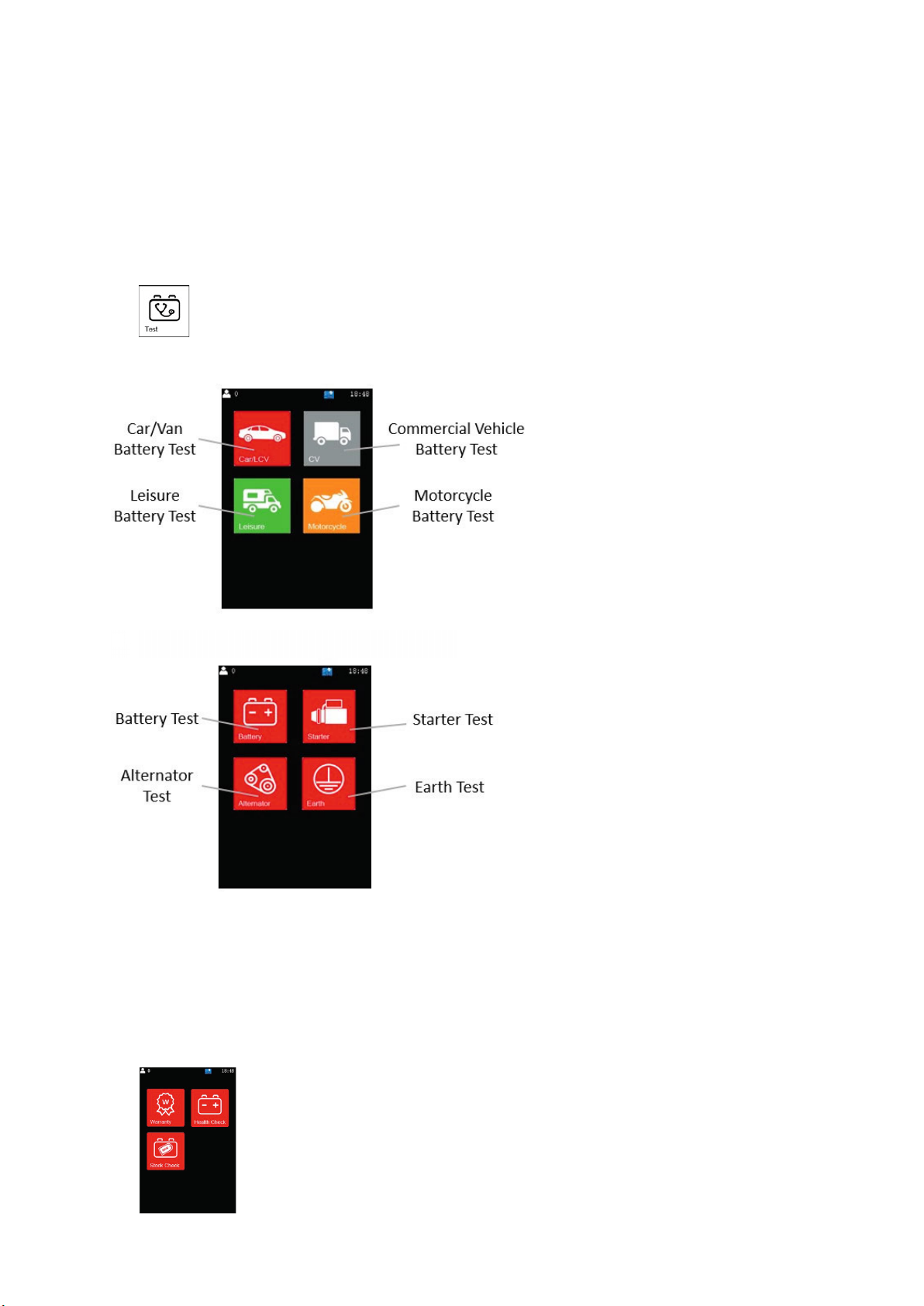
Battery testing
Testing method: Load free microprocessor-controlled conductance test
Applications: Automotive, commercial vehicle, motorcycle, powersport & leisure
Test types: Warranty, health check & stock check
Battery technologies : Conventional, EFB & AGM lead acid
Test range: Up to 2000A (EN) CCA
Input Voltage range : 9V to 36V
Starter, alternator & earth testing
Applications: Automotive & commercial vehicles with 12V or 24V electrical
system
Test types: Starter, alternator (diode ripple) & earth test
System technologies : Normal & smart alternators

1. Overview
The GYT250 can perform warranty, health and stock tests on conventional, EFB, AGM and
leisure batteries. It can also give a comprehensive overview of a vehicle’s starter and
charging system health through alternator, starter and earth checks. Results can be printed
using the built-in thermal printer or transferred to a computer via the SD card.
2. Connections & controls
8 – PRINT button
9 – Printing in progress indicator (RED)
10 – Printer paper out indicator (GREEN)
11 – Thermal printer
The red positive connection (2) should be attached to the battery’s positive terminal (+).
The black negative connection (3) should be connected to the battery’s negative (-)
terminal. The unit will then power up.
3. Printer paper installation
Open the printer cover and insert a roll of thermal printer paper
Close the cover making sure the thermal paper is held between the feed rollers
When the paper needs replacing the printer paper out indicator (10) will flash
3
)')/, %-*'1
3! *)-%.%0!)((!.%)(
3'&(!#.%0!)((!.%)(
3, -').
30%#.%)(/..)(-
3/..)(
3/..)(

4. Home screen
When the GYT250 is connected to a battery, the home screen will be displayed. From here
it is possible to start a test, manage previous results and configure the tester.
5. Settings menu
5.1 Set workshop name & contact details
Select Settings > Details
Use keys to select a character, then press ENTER
To move to another line, select navigation key then press ENTER
The character will appear, and the cursor can be moved to next line
Select the navigation key again to return to normal edit mode
Once all details have been entered select save icon then press ENTER
5.2 Set time & date
Select Settings > Time/Date
Use to move between entries, then use to set the time and date
Press ENTER to confirm and exit

5.3 Set sound
Select Settings > Sound
Press to turn sound OFF or to turn sound ON
Press ENTER to confirm and exit.
6. Starting a new test
To start a new test, first select Test from the Home Screen
Select the type of vehicle to be tested
7. Battery Test
The following tests help determine battery health during warranty, in-service or pre-service
checks
After selecting Battery Test, choose type of battery test required
!'!..$!.1*!)".!-.,!+/%,!

Warranty – For testing of batteries presented for warranty claims
Health Check – Determines the state of health, Voltage & CCA performance of batteries
that have been used on a vehicle
Stock Check – For battery stock management testing of new batteries that are in
storage prior to being installed in a vehicle
Note: Depending on the vehicle type selected, not all battery tests will be available
Follow the sequence below to enter battery details
Enter type > Enter test standard> Set battery rating > Testing starts
After testing, the results will be displayed
Note: Depending on the test type selected presentation of results will differ
Result / action Note
Battery is OK No
action required
Battery is OK
But a recharge is recommended
Battery is discharged Re-charge
before testing again
Battery is Weak
Replacement recommended
Service-related failure (rejected
claim under warranty test)
Bad Cell detected Replacement
recommended
Manufacturing defect (accepted
claim under warranty test)
N

7.1 Print results
Press PRINT button (8) then select required print option
If Quick Print is selected, results are printed without adding a customer reference
If Customer Details are selected then a reference (e.g. vehicle registration) can be
added by navigating the keyboard
When finished, select the save icon to exit and results will be printed
8. Starter Test
This test helps determine the condition of the starter motor and battery during engine
cranking. The drop of battery Voltage during the starting process is measured. This can
indicate if the battery has aged or the starter motor has a problem.

After selecting Starter Test the Voltage trace will be displayed
Start the engine and the results will be automatically recorded
After analysis results will be displayed
Result / action
Battery Volt drop is OK No
action required
Battery Volt drop too high Check
battery, starter & connections
Results can now be printed (see section 7.1)
9. Alternator Test
This test confirms if the alternator charging Voltage is within the correct limits to avoid under
or overcharging of the battery. There are three parts to the test:
2 Unloaded (Upper Voltage) check – High engine revs with accessories OFF
2 Loaded (Lower Voltage) check – Low engine revs with accessories ON
2 Diode Ripple check – Idle engine revs with headlights ON
1. After selecting Alternator Test choose the alternator type which matches the vehicle.
If in doubt choose Normal. Next generation vehicles with micro-hybrid technology
(including Start-Stop and regenerative breaking) would typically have a smart alternator.

9.1 Unloaded (Upper Voltage) Test
Ensure all vehicle accessories are switched OFF
Rev the engine to 3000rpm, press ENTER then hold revs for 10 seconds
Press ENTER > Hold for 10 secs
The analyser will automatically move to the next step
9.2 Loaded (Lower Voltage) Test
Ensure all vehicle accessories are switched ON e.g. lights, heater, demister
Rev the engine to 2000rpm, press ENTER then hold revs for 10 seconds
The analyser will automatically move to the next step
9.3 Diode ripple Test
Ensure that only the vehicle lights are switched ON
Set the engine at idle revs (700-1000rpm), press ENTER then wait for 10 seconds
,!--)' "),-!-

9.4 Alternator results summary
1. After analysis results will be displayed
Results can now be printed (see section 7.1)
The tables below show the acceptable Voltage ranges for each type of vehicle and
alternator. Any values outside of these ranges will be highlighted in the results.
Normal alternators
12V vehicles 24V vehicles
MIN
Voltage
MAX
Voltage
MIN
Voltage
MAX
Voltage
Unloaded (Upper Voltage)
Test > 13.3V < 15.0V > 26.6V < 30.0V
Loaded (Lower Voltage) Test > 12.6V > 13.8V > 25.2V > 27.6V
Smart alternators
12V vehicles 24V vehicles
MIN
Voltage
MAX
Voltage
MIN
Voltage
MAX
Voltage
Unloaded (Upper Voltage)
Test > 12.4V < 16.2V > 24.8V < 33.0V
Loaded (Lower Voltage) Test > 12.0V > 12.4V > 24.0V > 24.8V
10. Earth Test
This test checks that the earth connections between battery, engine and vehicle chassis are
in good condition. A high resistance caused by loose or corroded connections can lead to
poor starting.
10.1 Test procedure
First select Earth Test then press ENTER
Move the GYT250 black clamp from the battery negative terminal (-) to a suitable
position on the vehicle chassis and press ENTER for analysis to take place

Press ENTER > Analysis
Within 15 seconds, move the black clamp from the vehicle chassis back to the battery
negative terminal (-)
Press ENTER > Analysis
After analysis results will be displayed
Result / Action
Earth connection is OK No
action required
High resistance detected
Check for loose or corroded
connections
Earth not detected
Check contacts & repeat procedure
Note:- The test can be repeated to check the earth between battery and engine. This time
move the clamp from the battery negative terminal (-) to a suitable metal part on the engine.
Results can now be printed (see section 7.1)
GS YUASA Battery Germany GmbH
Europark Fichtenhain B17
47807 Krefeld
Germany
Phone: +49 2151 82095-00
www.yuasa.de
Other manuals for GYT250
1
Table of contents
Other gs yuasa Test Equipment manuals