IFM O3M ZZ1103 Manual

Instructions for set-up
O3M
Area surveillance
ZZ1103
80299235 / 00 04 / 2021
UK

O3M area surveillance
2
Contents
1 Preliminary note � � � � � � � � � � � � � � � � � � � � � � � � � � � � � � � � � � � � � � � � � � � � � � � � � � � � � � � � � � � � � � � � � � � �3
1�1 Symbols used � � � � � � � � � � � � � � � � � � � � � � � � � � � � � � � � � � � � � � � � � � � � � � � � � � � � � � � � � � � � � � � � � �3
1�2 Warnings used � � � � � � � � � � � � � � � � � � � � � � � � � � � � � � � � � � � � � � � � � � � � � � � � � � � � � � � � � � � � � � � � �3
1�3 Further documents � � � � � � � � � � � � � � � � � � � � � � � � � � � � � � � � � � � � � � � � � � � � � � � � � � � � � � � � � � � � � �3
2 Safety instructions � � � � � � � � � � � � � � � � � � � � � � � � � � � � � � � � � � � � � � � � � � � � � � � � � � � � � � � � � � � � � � � � � �4
2�1 Safety note illumination unit � � � � � � � � � � � � � � � � � � � � � � � � � � � � � � � � � � � � � � � � � � � � � � � � � � � � � � �4
2�2 Safety note E2M monitor � � � � � � � � � � � � � � � � � � � � � � � � � � � � � � � � � � � � � � � � � � � � � � � � � � � � � � � � �5
3 Intended use� � � � � � � � � � � � � � � � � � � � � � � � � � � � � � � � � � � � � � � � � � � � � � � � � � � � � � � � � � � � � � � � � � � � � � �5
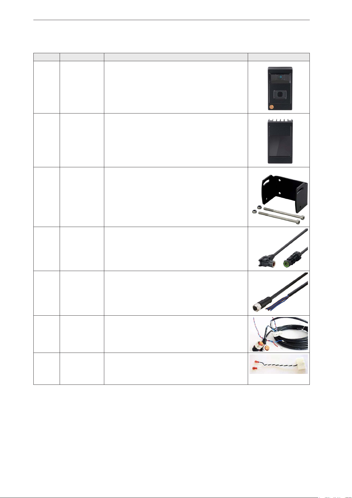
4 Items supplied� � � � � � � � � � � � � � � � � � � � � � � � � � � � � � � � � � � � � � � � � � � � � � � � � � � � � � � � � � � � � � � � � � � � � �6
5 Getting started � � � � � � � � � � � � � � � � � � � � � � � � � � � � � � � � � � � � � � � � � � � � � � � � � � � � � � � � � � � � � � � � � � � � �9
5�1 Connection overview � � � � � � � � � � � � � � � � � � � � � � � � � � � � � � � � � � � � � � � � � � � � � � � � � � � � � � � � � � �10
5�2 Mounting� � � � � � � � � � � � � � � � � � � � � � � � � � � � � � � � � � � � � � � � � � � � � � � � � � � � � � � � � � � � � � � � � � � � �12
5�3 Setting the area surveillance � � � � � � � � � � � � � � � � � � � � � � � � � � � � � � � � � � � � � � � � � � � � � � � � � � � � �14
6 Function � � � � � � � � � � � � � � � � � � � � � � � � � � � � � � � � � � � � � � � � � � � � � � � � � � � � � � � � � � � � � � � � � � � � � � � � �17
6�1 Mobile 3D smart sensor � � � � � � � � � � � � � � � � � � � � � � � � � � � � � � � � � � � � � � � � � � � � � � � � � � � � � � � � �17
6�2 CAN bus � � � � � � � � � � � � � � � � � � � � � � � � � � � � � � � � � � � � � � � � � � � � � � � � � � � � � � � � � � � � � � � � � � � �17
6�3 Application package � � � � � � � � � � � � � � � � � � � � � � � � � � � � � � � � � � � � � � � � � � � � � � � � � � � � � � � � � � � �17
7 Mounting� � � � � � � � � � � � � � � � � � � � � � � � � � � � � � � � � � � � � � � � � � � � � � � � � � � � � � � � � � � � � � � � � � � � � � � � �18
7�1 Mounting the BasicController � � � � � � � � � � � � � � � � � � � � � � � � � � � � � � � � � � � � � � � � � � � � � � � � � � � � �18
7�2 Mounting the 3D sensor and illumination unit� � � � � � � � � � � � � � � � � � � � � � � � � � � � � � � � � � � � � � � � �18
7�3 Measuring the inclination angle and height of the 3D sensor� � � � � � � � � � � � � � � � � � � � � � � � � � � � �20
7�4 Example of mounting the 3D sensor on the vehicle rear � � � � � � � � � � � � � � � � � � � � � � � � � � � � � � � �21
8 Electrical connection� � � � � � � � � � � � � � � � � � � � � � � � � � � � � � � � � � � � � � � � � � � � � � � � � � � � � � � � � � � � � � � �22
8�1 Wiring 3D sensor � � � � � � � � � � � � � � � � � � � � � � � � � � � � � � � � � � � � � � � � � � � � � � � � � � � � � � � � � � � � � �24
8�2 Wiring illumination unit � � � � � � � � � � � � � � � � � � � � � � � � � � � � � � � � � � � � � � � � � � � � � � � � � � � � � � � � � �24
8�3 Wiring BasicController � � � � � � � � � � � � � � � � � � � � � � � � � � � � � � � � � � � � � � � � � � � � � � � � � � � � � � � � � �25
8�4 Wiring E2M monitor � � � � � � � � � � � � � � � � � � � � � � � � � � � � � � � � � � � � � � � � � � � � � � � � � � � � � � � � � � � �26
8�5 Connecting the BasicController to the BasicDisplay � � � � � � � � � � � � � � � � � � � � � � � � � � � � � � � � � � �26
8�6 Connecting the 3D sensor and illumination unit � � � � � � � � � � � � � � � � � � � � � � � � � � � � � � � � � � � � � � �29
8�7 Connecting the E2M Monitor � � � � � � � � � � � � � � � � � � � � � � � � � � � � � � � � � � � � � � � � � � � � � � � � � � � � �29
9 Operating and display elements � � � � � � � � � � � � � � � � � � � � � � � � � � � � � � � � � � � � � � � � � � � � � � � � � � � � � � �30
9�1 BasicDisplay � � � � � � � � � � � � � � � � � � � � � � � � � � � � � � � � � � � � � � � � � � � � � � � � � � � � � � � � � � � � � � � � � �30
9�2 Buzzer � � � � � � � � � � � � � � � � � � � � � � � � � � � � � � � � � � � � � � � � � � � � � � � � � � � � � � � � � � � � � � � � � � � � � �30
10 Set-up � � � � � � � � � � � � � � � � � � � � � � � � � � � � � � � � � � � � � � � � � � � � � � � � � � � � � � � � � � � � � � � � � � � � � � � � � �31
10�1 Setting the area surveillance � � � � � � � � � � � � � � � � � � � � � � � � � � � � � � � � � � � � � � � � � � � � � � � � � � � �31
10�1�1 Start screen and operating status� � � � � � � � � � � � � � � � � � � � � � � � � � � � � � � � � � � � � � � � � � � � �32
10�1�2 Expert settings � � � � � � � � � � � � � � � � � � � � � � � � � � � � � � � � � � � � � � � � � � � � � � � � � � � � � � � � � � �33
10�1�3 Configuration wizard� � � � � � � � � � � � � � � � � � � � � � � � � � � � � � � � � � � � � � � � � � � � � � � � � � � � � � �37
10�1�4 Zone definition - default settings� � � � � � � � � � � � � � � � � � � � � � � � � � � � � � � � � � � � � � � � � � � � � �40
10�1�5 Zone definition - expert settings � � � � � � � � � � � � � � � � � � � � � � � � � � � � � � � � � � � � � � � � � � � � � �41
10�2 Monitoring mode� � � � � � � � � � � � � � � � � � � � � � � � � � � � � � � � � � � � � � � � � � � � � � � � � � � � � � � � � � � � � �43
11 Troubleshooting � � � � � � � � � � � � � � � � � � � � � � � � � � � � � � � � � � � � � � � � � � � � � � � � � � � � � � � � � � � � � � � � � �44
11�1 Status LED � � � � � � � � � � � � � � � � � � � � � � � � � � � � � � � � � � � � � � � � � � � � � � � � � � � � � � � � � � � � � � � � � �44
11�2 Operating states � � � � � � � � � � � � � � � � � � � � � � � � � � � � � � � � � � � � � � � � � � � � � � � � � � � � � � � � � � � � � �45
11�3 Status indications in monitoring mode � � � � � � � � � � � � � � � � � � � � � � � � � � � � � � � � � � � � � � � � � � � � �45
11�4 Error codes 3D sensor � � � � � � � � � � � � � � � � � � � � � � � � � � � � � � � � � � � � � � � � � � � � � � � � � � � � � � � � �47
11�5 Error codes BasicController � � � � � � � � � � � � � � � � � � � � � � � � � � � � � � � � � � � � � � � � � � � � � � � � � � � � �48
12 Terms and abbreviations� � � � � � � � � � � � � � � � � � � � � � � � � � � � � � � � � � � � � � � � � � � � � � � � � � � � � � � � � � � �49
13 Frequently asked questions � � � � � � � � � � � � � � � � � � � � � � � � � � � � � � � � � � � � � � � � � � � � � � � � � � � � � � � � �49
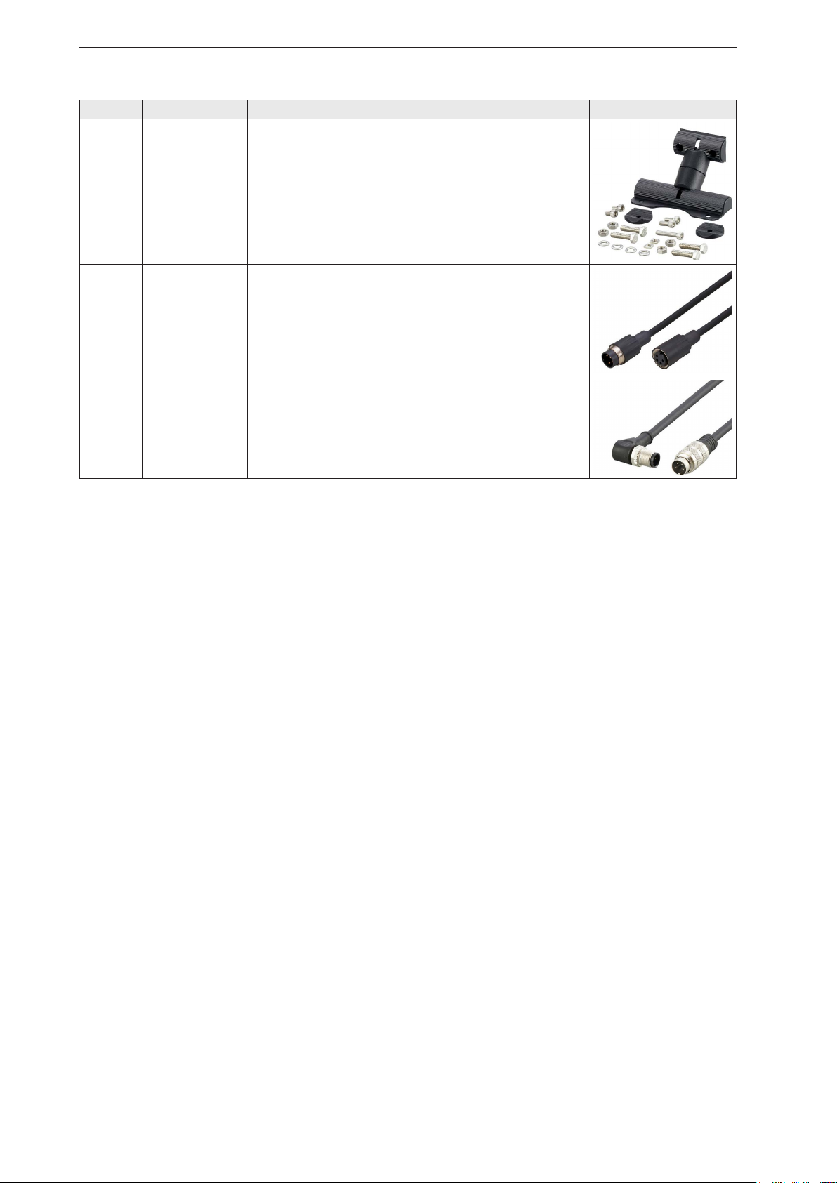
14 Accessories� � � � � � � � � � � � � � � � � � � � � � � � � � � � � � � � � � � � � � � � � � � � � � � � � � � � � � � � � � � � � � � � � � � � � �52

3
O3M area surveillance
UK
1 Preliminary note
Operating instructions of the individual devices, technical data, approvals, accessories and further
information → www.ifm.com.
The product page of the ZZ1103 contains the instructions for set-up in several
languages:
1.1 Symbols used
►
Instruction
>
Reaction, result
[…]
Designation of keys, buttons or indications
→
Cross-reference
Important note
Non-compliance may result in malfunction or interference�
Information
Supplementary note�
1.2 Warnings used
WARNING
Warning of serious personal injury�
Death or serious irreversible injuries may result�
CAUTION
Warning of personal injury�
Slight reversible injuries may result�
NOTE
Warning of damage to property
1.3 Further documents
●Quick reference guide
●Operating instructions
●Software manual
Download the documents at → www.ifm.com

O3M area surveillance
4
2 Safety instructions
●The devices described are integrated into a system as components�
– The operator is responsible for the safety of the system�
– The system architect undertakes to perform a risk assessment and to create documentation in
accordance with legal and normative requirements to be provided to the operator and user of the
system� This documentation must contain all necessary information and safety instructions for the
operator, the user and, if applicable, for any service personnel authorised by the architect of the system�
– The system architect is responsible for the functioning of the application programs�
●Read this document before setting up the devices and keep it during the entire service life�
●The devices must be suitable for the corresponding applications and environmental conditions without
any restrictions�
● Use the devices for their intended purpose (→ "3 Intended use").
●If the operating instructions or the technical data are not adhered to, personal injury and/or damage to
property may occur�
●The manufacturer assumes no liability or warranty for any consequences caused by tampering with
the devices or incorrect use by the operator�
●Installation, electrical connection, set-up, programming, configuration, operation and maintenance of
the devices must only be carried out by qualified and authorised personnel for the respective activity�
●Protect devices and cables against damage�
●Because of the requirements for electromagnetic interference emissions, the devices are intended for
use in industrial environments� The devices are not suitable for use in domestic areas�
WARNING
If the set is used for operator protection, death or serious irreversible injuries are possible�
The set is an assistance system and only supports the detection of objects� The operator of the
system bears full responsibility for persons within the monitored area�
►Only use the set as an assistance system�
2.1 Safety note illumination unit
CAUTION
Invisible infrared light
The illumination unit emits infrared light of risk group 1 (IEC 62471:2006) invisible to the
human eye�
The infrared light can damage the retina of the eye when staring at it for a very long time�
►Use the illumination unit with the described devices and settings�
►Avoid staring into the infrared beam�
NOTICE
IR light emitted from this product.
Classification acc. to IEC 62471:2006
Risk Group 1
Fig� 1: Safety note regarding the illumination unit

5
O3M area surveillance
UK
2.2 Safety note E2M monitor
NOTE
Touching the display may result in permanent pixel errors�
►Do not touch the screen�
3 Intended use
The ZZ1103 O3M area surveillance set is an assistance system for area surveillance and collision
warning� The set includes all devices and cables necessary for operation� The devices are pre-
programmed and can be put into operation directly after installation and electrical connection to 12 V or
24 V on-board systems�
The ZZ1103 set can be used outdoors and indoors� The main application is active or static area
surveillance of large vehicles and mobile machines� Objects detected in the hazardous area are signalled
to the driver visually and acoustically� The following areas of a vehicle can be monitored:
●Front
●Rear
●Sides
The ZZ1103 O3M area surveillance set does not relieve the driver of his responsibility to operate the
vehicle safely�
More information: www�ifm�com and mobilevision@ifm�com

O3M area surveillance
6
4 Items supplied
Number Article number Description Photo
1 O3M261 Mobile 3D sensor with integrated 2D/3D overlay (pre-
programmed)
Angle of aperture 3D: 95°x32°
1 O3M960 IR illumination unit for O3M261
2 E3M102 Mounting bracket for 3D sensor and illumination unit,
stainless steel, black
1 E3M120 MCI connection cable for 3D sensor and illumination
unit
1 E3M133 Connection cable for illumination unit, length 10 m
1 E3M171 CAN adapter cable with integrated CAN terminating
resistor (120 ohm) for connection and power supply
of 3D sensor, CR0403 and CR0451, 10 m
1 E3M172 Adapter cable for the connection of the buzzer and
use of the output channels�
The package contains additional connection cables
for further output channels�

7
O3M area surveillance
UK
Number Article number Description Photo
1 80281057 Buzzer 24 V for connection to CR0403
Depending on the operating voltage, use the
buzzer for 12 V or 24 V�
1 80303178 Buzzer 12 V for connection to CR0403
Depending on the operating voltage, use the
buzzer for 12 V or 24 V�
1 CR0403 BasicController, programmable controller with
multifunctional input and output channels (pre-
programmed)
1 EC0402 Cover for BasicController as protection against
moisture and dust (IP54)
1 CR0451 BasicDisplay, programmable graphic display with
CAN connection (pre-programmed)
1 E2M231 7" TFT LCD monitor 12...32 V DC with LED backlight,
1 video input for display of the camera image

O3M area surveillance
8
Number Article number Description Photo
1 E2M239 Bracket for monitor E2M231
1 E2M203 Connection cable for analogue video signal, M16
connector to M16 socket, 5 m, black, PVC
1 E3M161 Analogue video adapter cable, M12 connector to M16
connector, for the connection of O3M261 to E2M203,
1 m, black

9
O3M area surveillance
UK
5 Getting started
The chapter "Getting started" provides a brief description of the installation, the electrical connection and
the set-up�
Fig� 2: Connected devices of the ZZ1103 set
E2M231
7“ TFT LDC monitor
ok
CR0451
CR0403
O3M261
3D sensor
O3M960
E3M171
E3M120
E3M133
E3M161
E2M203
E2M231
12/24 V
DC
80281057 or
80303178
E3M172
E3M171
E3M171
Fig� 3: Overview of the connected devices
Depending on the operating voltage, use the buzzer for 12 V (80303178) or 24 V (80281057).

O3M area surveillance
10
5.1 Connection overview
The table contains the electrical connection of the devices. The column "Connection" contains the
connections of the devices. The column "Connection target" contains the target of the respective
connection�
The devices can be connected to 12 V or 24 V on-board systems�
Article Photo Wiring Connection Connection target
E3M171 Terminal block
M12 socket, long
cable
M12 socket, short
cable
Wire, brown
Wire, blue
→ ①CR0403
→ ①O3M261, M12
connector
→ ①CR0451
→ U+ (8...32 V DC)
→ GND
O3M261
4
① CAN / power
②Ethernet
③MCI
④Video output
→ E3M171, long cable, M12
Not used�
►Protect the socket from
moisture with a protective
cap�
→ E3M120, angled
→ E3M161
O3M960 ① MCI
②Power
→ E3M120, not angled
→ E3M133
①

11
O3M area surveillance
UK
Article Photo Wiring Connection Connection target
E3M120 Angled
Not angled
→ O3M261
→ O3M960
E3M133 M12 socket
Wires, brown
Wires, blue
→ O3M960
→ U+ (9...32 V DC)
→ GND
E3M172 Terminal block
Wire, white
Wire, black
→ ②CR0403
→ 80281057, terminal 30
→ 80281057, terminal 31b
80281057
/
80303178
30
31b
Terminal 30
Terminal 31b
→ E3M172, white
→ E3M172, black
CR0403
A B C D E F
N2
P/N1
① Inputs
② Outputs
③Power / CAN
→ optional (IN011: standby)
→ E3M172
→ E3M171
CR0451 ① CAN → E3M171 , short, M12
E2M231
1 2
① Power
② Video input
→ red
:
U+ (12...32 V DC)
→ white: GND
→ E2M203
Older versions of the device have a voltage range of 18...30 V DC (revision no. AA).
Current devices have a voltage range of 12...32 V DC (revision no. AB).
►Observe the voltage range on the type label�
> The type label indicates the voltage range of the device�
②

O3M area surveillance
12
Article Photo Wiring Connection Connection target
E2M203 M16 connector
M16 socket
→ E2M231, video input
→ E3M161, M16 connector
E3M161 M16 connector
M12 connector
→ E2M203, M16 socket
→ ④O3M261, M12 socket
5.2 Mounting
►Connect the devices as shown in Fig� 3�
► Mount the 3D sensor as centrally as possible at the front of the vehicle roof (see Fig. 11).
> If central mounting of the 3D sensor is not possible: Use the zone definition to compensate for the
deviation (→ "10.1.5 Zone definition - expert settings").
► Viewed from the front, mount the illumination unit directly to the right of the 3D sensor (see Fig. 8).
> Otherwise, the recognition rate of objects is reduced�
> The mounting position of the 3D sensor and the illumination unit is selected so that the field of view
and the measuring range of the 3D sensor cover the area to be monitored�
The following values apply to the 3D sensor and the illumination unit:
3D image 2D image
Field of view 95° x 32° 120° x 90°
Measuring
range
approx� 8 m > 8 m
The 2D image covers a larger measuring range than the 3D image�
The table contains exemplary values for various mounting positions (depending on the mounting location,
taking into account a minimum distance A in front of the 3D sensor).
Mounting height
h[m]
Recommended
inclination angle
α [°]
Min�
distance A
[m]
Max�
distance B
[m]
Width at the
vehicle C[m]
Width at the end of
the field of view D
[m]
2D 3D 2D 3D
1�6 20 0�5 8 2�2 1�5 30 19�5
2 29 0�6 5�6 3 2 20 13
2�2 34 0�6 4�6 3�6 2�4 17 11
2�4 38 0�7 4�2 4�3 2�8 16 10
2�6 42 0�7 3�9 4�9 3�2 15 9�8
2�8 46 0�7 3�6 5�5 3�6 14�5 9�5
3 48 0�7 3�5 6 4 14�5 9�5
Fig. 4 shows the 3D sensor with illumination unit mounted on a vehicle. The letters "A-D" are assigned to
values from the previous table�
4

13
O3M area surveillance
UK
Fig� 4: Schematic representation of the 3D field of view of a mounted 3D sensor
Fig. 5 shows the 3D sensor with illumination unit mounted on an excavator. The letters "h" and"α" are
assigned to values from the previous table�
Fig� 5: 3D sensor with illumination unit mounted on the rear of an excavator

O3M area surveillance
14
5.3 Setting the area surveillance
The area surveillance is divided into 3 zones� The zones represent risk levels, with the [ ] zone
representing the lowest risk level and the [ ] zone representing the highest risk level� The size of
the zones can be adjusted for different vehicles and scenarios� The distance to the detected object
determines the active zone�
If an object is detected in a zone, this causes a change to:
●the output of the BasicController,
●the background and text colour of the BasicDisplay,
● the acoustic signal emitted (if a buzzer is connected).
In the following, the area surveillance is set via the BasicDisplay� Once the setting has been carried out,
the monitoring mode is activated and the system is ready for operation (→ "10.2 Monitoring mode").
Use the following key combination to switch back to the operating status from any menu:
► Press the 4 function keys simultaneously (→ "9 Operating and display elements").
Start screen Operating status Device information
The start screen is displayed
when the system is started�
The system status shows the
operating status of the devices (→
"11.2 Operating states").
After power-on, it takes up to
30 sec until all devices are
ready for operation�
The device information shows
information about the individual
devices of the set:
●Serial number
●Firmware and library versions
●Operating status
Assignment of the function keys
[] Select language [Info] Display the device information
[Monitor] Start monitoring mode [Assist] Start configuration wizard
[Back] Show previous screen [Expert] Start expert settings
Assignment of the navigation keys
[◄] Show previous screen [►] Show next screen

15
O3M area surveillance
UK
Calibration Automatic calibration
The measured height and
inclination angle of the 3D sensor
are entered manually�
The values must be measured
beforehand (→ "7.3 Measuring
the inclination angle and height
of the 3D sensor").
The automatic calibration is trying to determine the inclination angle
and height of the 3D sensor�
For automatic calibration, the 3D sensor must have a clear view
of the ground (approx. 3 m wide and 3 m long).
The automatic calibration may take up to 80 s�
If the exact inclination angle and height are known, the
automatic calibration can be skipped�
The following statuses are displayed:
● "searching": The 3D sensor is automatically calibrated.
●“successful”: The automatic calibration has been completed
successfully�
● "not successful": The automatic calibration has not been
completed successfully� The automatic calibration is not
mandatory� It is also possible to use only the manually entered
values�
At the end of the calibration, the detected values are displayed for
checking�
►Accept the displayed values with [Next]�
Object detection type Zone definition
The object detection type determines
how objects are treated:
●[Standard]: Objects and reflectors
are detected in all zones� No
distinction is made between objects
and reflectors�
●[Reflector]: In the [ ] zone, only
objects with reflectors are detected
(e.g. safety vests).
In the [ ] and [ ] zone, objects
and reflectors are detected�
The [Reflector] setting is
recommended for steep ramps�
The zone definition determines how the zone widths are set:
●[Quick setup]: The same value is set for the left and right
areas of the zone (→ "10.1.4 Zone definition - default
settings").
The setting is recommended if the 3D sensor is
mounted centrally on the vehicle�
●[Expert setup]: The left and right areas of the zone are set
separately (→ "10.1.5 Zone definition - expert settings").
The setting is recommended
●if the 3D sensor is not mounted centrally on the
vehicle or
●in case of an asymmetrical vehicle geometry�

O3M area surveillance
16
Zone definition Zone definition - zones
Via the zone definition, the width
and length of the zones can
be set� The zones represent
risk levels, with the [ ] zone
representing the lowest risk level
and the [ ] zone representing
the highest risk level�
Objects within the [ ] zone
are ignored� This is particularly
suitable for obstructions in the
detection range of the 3D sensor�
The width and length of the zones can be set� The same value is
set for the left and right areas of the zone� Adding the left and right
areas gives the total width�
The minimum detection height is set under "min. height". Objects
below the minimum detection height are ignored� This reduces false
triggering by
●ramps,
●uneven ground,
●objects close to the ground�
Zone definition - zones
Save the set zone values�
Assignment of the function keys
[Back] Show previous screen [Next] Save input and display next screen
[] Set the length and width of the [ ] zone [ ] Set the length and width of the [ ] zone
[ ] Set the length and width of the [ ] zone [ ] Set the length and width of the [ ] zone
[-] Decrease selected value [+] Increase selected value
[ok] Confirm input [Yes] Save input
[No] Don’t save input
Assignment of the navigation keys
[▲] Select the previous menu item [▼] Select next menu item
[◄] Show previous screen [►] Show next screen
Once the area surveillance has been set, the system is ready for operation and runs in monitoring
mode� The BasicDisplay shows on the screen in which zone an object has been detected� If the E2M
monitor is connected, the risk level is additionally displayed there�

17
O3M area surveillance
UK
6 Function
The devices included in the ZZ1103 set make up an assistance system that supports the surveillance of
hazardous areas� A hazardous area can be, for example, the blind spot of mobile machines�
6.1 Mobile 3D smart sensor
The mobile 3D smart sensor is approved for operation on mobile machines� The mobile 3D smart sensor
consists of an active 3D sensor with 1024 pixels, which provides 1024 distance values simultaneously�
For this, the "time-of-flight" measurement principle is used.
6.2 CAN bus
All necessary signals are available via the CAN bus� The O3M261 3D sensor sends data via the CAN bus
to the CR0403 BasicController and the CR0451 BasicDisplay�
6.3 Application package
The area surveillance application package included in the ZZ1103 set allows easy use of the above-
mentioned technologies on mobile machines� No programming is required� The application package is
configured via the setting help on the BasicDisplay� 3 rectangular warning zones are configured� Each
warning zone can react independently to different objects and signals� If something is detected in a
warning zone, the system provides warnings:
●acoustic signal via the buzzer,
●visual signal via the BasicDisplay,
●graphical representation in the live image of the E2M monitor�
Detailed information on the operating principle can be found in the operating instructions of the
devices�

O3M area surveillance
18
7 Mounting
7.1 Mounting the BasicController
NOTE
The BasicController and the BasicDisplay can be damaged when installed in engines�
►Install the BasicController and the BasicDisplay in vehicle bodies�
①
①①
①
►Mount the BasicController to a suitable surface using
the screw-on points ①�
Fig� 6: Mounting the BasicController
7.2 Mounting the 3D sensor and illumination unit
From the mounting location of the 3D sensor, the desired area is monitored� The decisive factors are the
field of view and the measuring range of the 3D sensor� The following values apply to the O3M261 3D
sensor and the O3M960 illumination unit included in the set:
3D image 2D image
Field of view 95° x 32° 120° x 90°
Measuring
range
approx� 8 m > 8 m
The 2D image of the 3D sensor covers a larger measuring range than the 3D image�
Fig� 7: 3D field of view of the O3M261 at a height of 1�7 m with an inclination angle of 45°
►Select the mounting position for the 3D sensor and the illumination unit�
> The supplied 3D sensor is suitable for monitoring very close areas�

19
O3M area surveillance
UK
The table contains exemplary values for various mounting positions (depending on the mounting location,
taking into account a minimum distance A in front of the 3D sensor).
Mounting height
h[m]
Recommended
inclination angle
α [°]
Min�
distance A
[m]
Max�
distance B
[m]
Width at the
vehicle C[m]
Width at the end of
the field of view D
[m]
2D 3D 2D 3D
1�6 20 0�5 8 2�2 1�5 30 19�5
2 29 0�6 5�6 3 2 20 13
2�2 34 0�6 4�6 3�6 2�4 17 11
2�4 38 0�7 4�2 4�3 2�8 16 10
2�6 42 0�7 3�9 4�9 3�2 15 9�8
2�8 46 0�7 3�6 5�5 3�6 14�5 9�5
3 48 0�7 3�5 6 4 14�5 9�5
►Mount the 3D sensor as centrally as possible at the front of the vehicle roof using the E3M102 bracket
(see Fig. 11).
> If central mounting of the 3D sensor is not possible: Use the zone definition to compensate for the
deviation (→ "10.1.5 Zone definition - expert settings").
Fig� 8: 3D sensor and illumination unit mounted side by side
►Viewed from the front, mount the illumination unit directly to the right of the 3D sensor using the
E3M102 bracket (see Fig. 8).
> The devices are calibrated for mounting directly next to each other� Otherwise, the recognition rate of
objects is reduced�
►Connect the 3D sensor to the illumination unit via the MCI connection cable�
Keep the area illuminated by the illumination unit free from any obstructions in a close range (up to
50 cm).
►Use cables with strain relief�

O3M area surveillance
20
7.3 Measuring the inclination angle and height of the 3D sensor
The 3D sensor must be calibrated before it can be used� The inclination angle and the height of the 3D
sensor are required for calibration�
The inclination angle and the height refer to the world coordinate system� Both values are required for
set-up (→ "10 Set-up").
Fig� 9: Measuring the inclination angle αwith a smartphone
The simplest way to measure the inclination angle α is to use a smartphone:
►Align the smartphone parallel to the straight line marked in red using an app for measuring angles�
> The straight line separates the two housing parts of the 3D sensor�
Fig� 10: Measuring the height via the reference socket of the 3D sensor
There is a reference socket (see Fig. 1) on the side of the 3D sensor. The height of the 3D sensor is
measured via this reference socket:
►Measure the distance from the ground to the reference socket of the 3D sensor marked in red�
Table of contents
Other IFM Security System manuals
Popular Security System manuals by other brands

Ei Electronics
Ei Electronics RadioLINK Base Smoke & Heat Alarms Ei168 Technical specifications

Novar ED&S
Novar ED&S Response PL4 installation manual

Thorne & Derrick
Thorne & Derrick rotronic CF3-W-US-Disp-FLI installation manual

NuTech
NuTech SX-3100LCD user manual

Eldes Alarms
Eldes Alarms FUMEREX user manual

ADT
ADT FOCUS CADET user guide