iGAZE TCOO900 User manual

iGAZE® REP KIT
BI-DIRECTIONAL
COMMUNICATION
Movable Device
TCOO900
Fixed Device
RCOO900P
INSTRUCTION MANUAL
v.05.24.18
Transceiver System for 10kΩ, or 8.2kΩ
Resistive Safety Edges
Pulsed output

2
TRANSCEIVER SYSTEM FOR SAFETY EDGES
TECHNICAL SPECIFICATIONS
QUICK START GUIDE
BELOW IS THE MOST COMMON INSTALLATION
Movable device name TCOO900
Fixed device name RCOO900P
Frequency 902-928 Mhz
Range of the system in free space 20 m / 60 feet
TCOO900 power supply 2 x 1.5V batteries (AA)
RCOO900P power supply 12/24 Vac-dc
Battery duration 2 years (normal functioning mode).
5 years (Low power mode).
Minimum battery level (TCOO900) 1.9V
Compatible safety edges (TCOO900) Resistive (8.2 kΩ / 10kΩ)
Number of outputs (RCOO900P) 2
Maximum number of Transmitters for each
RCOO900P
8 for each device.
Maximum number of safety edges for each output 8 for each relay.
Power draw on RCOO900P (24Vdc) 15mA (3-wire or 4-wire pulsed)
50mA (2-wire pulsed)
Resistive Safety Edge (max value) 5kOhm < R < 20KOhm (safety edge OK)
R<5KOhm (safety edge in short circuit)
R>20KOhm (OPEN safety edge)
Frequency for alternate current (RCOO900P) 50-60Hz
Operating Temperature -10°C to +55°C / 14°F to 131°F
TCOO900 - Both safety edges are 8.2kΩ or
10kΩ resistive.
RCOO900P - Pulsed 2 Frequency on both
channels
12 3 OFF
ON
Resistive
edge 2
Resistive
edge 1
Resistive edge 2
8.2kΩ / 10kΩ (N.C.)
Dip switch
Led and
programming /
test key 2
Led and
programming /
test key 1
Resistive edge 1
8.2kΩ / 10kΩ (N.C.)
Safety2
Safety1
DIP
12/24
Vac/Vdc
+-
operator 1
pulsed input
operator 2
pulsed input
2Freq/3Freq
Buzzer OFF
Frequency
Out1 - 10k
Out2 - 10k
OFF ON
Programming/
Reset key
Buzzer
RCO900P

3
STEP 2
STEP 1
DESCRIPTION
CONFIGURATION AND ELECTRICAL CONNECTIONS
The iGAZE®REP transceiver system is intended as a safety device for automated gates and rolling doors. The system is
comprised of 1 fixed device (RC00900P) with 2 pulsed outputs, which is connected to the operator, and up to 8 movable
devices (TC00900) for each relay. The system TCOO900 will accept only resistive safety edge 10kΩor 8.2kΩ. The
transmission signal is bi-directional and utilizes the frequencies 902-928MHz. Maximum range between the movable and
fixed devices is 60 feet.
TCOO900 is suitable for outdoor use. RCOO900P is suitable for indoor use only (“indoor” means inside the
operator box). The installation of the system must be carried out by a qualified installer.
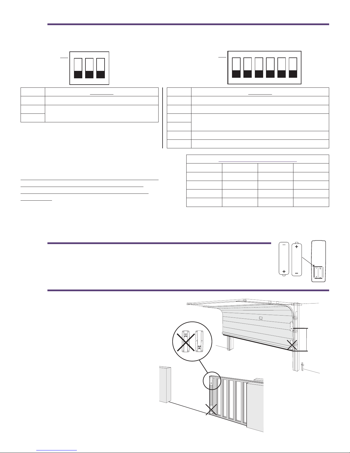
CONNECT THE SAFETY EDGE TO THE SAFETY EDGE MOVABLE DEVICE (TCOO900)
DIP SWITCHES CONFIGURATION OF TCOO900
EXAMPLE 1 - Both safety edges are 8.2kΩ or 10kΩ resistive
12 3 OFF
ON
Resistive
edge 2
Resistive
edge 1
Resistive edge 2
8.2kΩ / 10kΩ (N.C.)
Dip switch
Led and
programming /
test key 2
Led and
programming /
test key 1
Resistive edge 1
8.2kΩ / 10kΩ (N.C.)
Safety2
Safety1
DIP
123
TCOO900
DIP
ON
OFF
(All switches in example above are set to OFF)
A
B
N°DIP Function
1Low Power (see section E on
page 9)
2Frequency channel selection
(see page 4)
3
ATTENTION! If external operators or devices are installed, wiring type CL2, CL2P, CL2R or CL2X complying with UL 13 or
other cable with equivalent or better electrical, mechanical, and flammability ratings shall be used.
4
STEP 3
STEP 4
It is possible to associate a maximum of 8 TCOO900
to each RCOO900P.
WARNING: for a correct functioning of the system,
every TCOO900 must have the frequency dip
switch set the same way as the corresponding
RCOO900P.
On a safety system with more than one Receiver, to avoid interference, we recommend the use of dierent frequency
settings on each set of a RCOO900P and the associated TCOO900.
POWER THE TCOO900 BY INSTALLING THE TWO AA BATTERIES (1.5V) INTO THE
BATTERY HOLDER. PLEASE NOTE THE CORRECT POLARITY.
1.5V
1.5V
N° DIP Function
1 Low power. (see Section E on page 9)
2Frequency channel selection
3
N° DIP Function
1 2 Freq / 3 Freq
2 Buzzer ON / OFF
3Frequency channel selection
4
5 Out1 type: N.O. contact (OFF) or 10k signal (ON) 1
6 Out2 type: N.O. contact (OFF) or 10k signal (ON) 2
Frequency channel selection
Channel Dip 3 (2) Dip 4 (3) Frequency
1 OFF OFF 912.900
2 OFF ON 914.900
3 ON OFF 916.900
4 ON ON 918.900
SET DIP SWITCHES 2 AND 3 ON THE TCOO900 AND 3 AND 4 ON THE RCOO900P TO THE SAME SETTINGS.
123
TCOO900
DIP
ON
OFF
123
RCOO900P
DIP
ON
OFF
4 5 6
STEP 5
Height min: 8”
Height
min: 8”
MOUNT THE TCOO900 AS HIGH AS POSSIBLE
AND IN SUCH A WAY AS THERE ARE NO
OBSTACLES IN THE DIRECTION OF THE
RCOO900P AND IN SUCH A WAY AS THE
MAXIMUM DISTANCE BETWEEN THE TWO
DEVICES IS LESS THAN 60 FEET (MAX 20
METERS / 60 FEET).
WARNING: install the TCOO900 at a minimum
height of 8” from the ground.
Keep the installation area clean of debris which
can eect the normal operation of the system.
NOTE: Transmitter Solutions is not responsible for
any damage caused by an improper, incorrect, or
unintended use of the product.
5
STEP 6
STEP 7
MOUNT THE RCOO900P AS CLOSE AS POSSIBLE TO THE TCOO900. IF MOUNTED TO A WALL, USE SUITABLE
SCREWS AND ANCHORS TO SECURE THE RCOO900P.
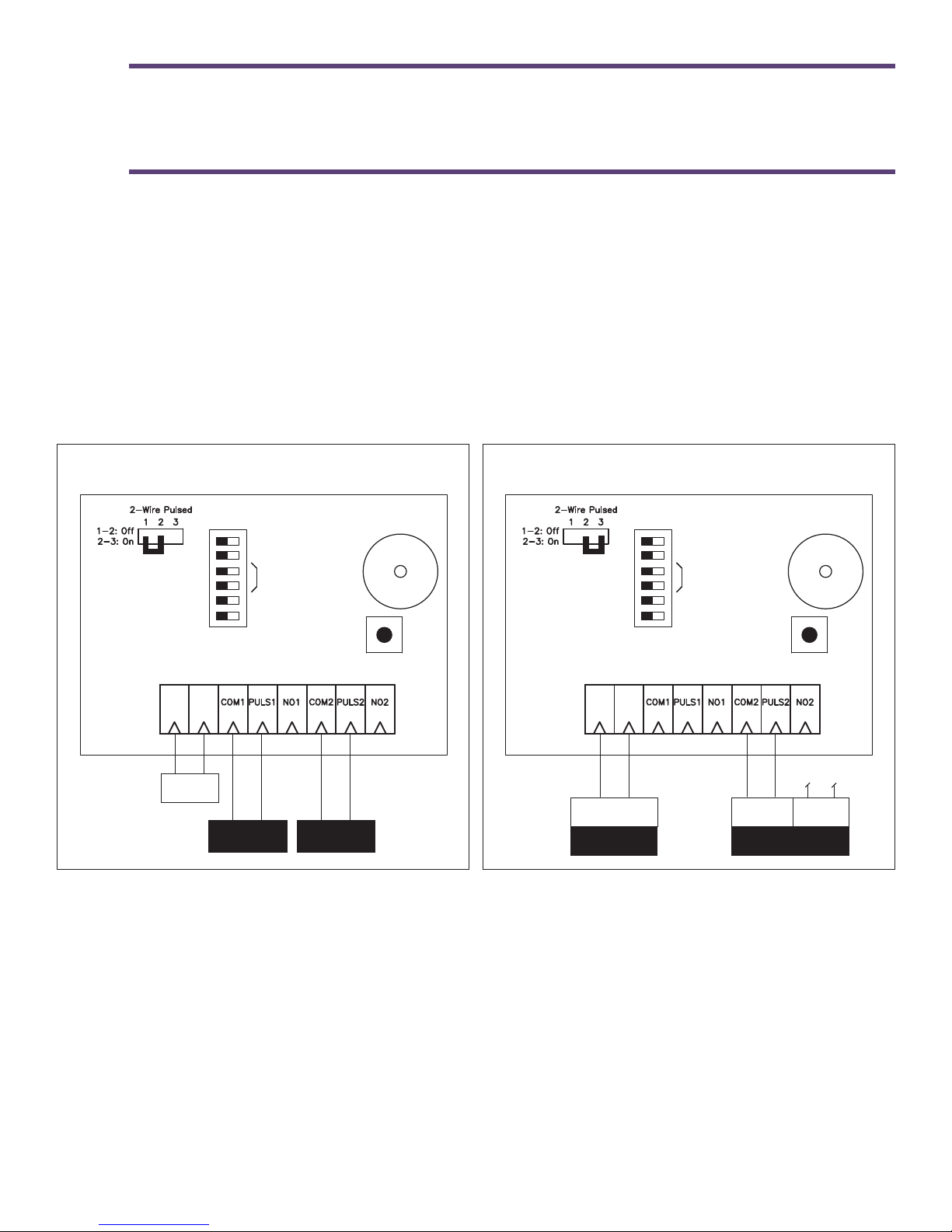
DEPENDING ON THE TYPE OF SIGNAL REQUIRED, CONNECT THE OUTPUTS AS EXPLAINED IN THE
FOLLOWING EXAMPLES.
NOTE: The signals given on the outputs 1 and 2 are a N.O. contact, resistive output (10kΩ) or pulsed output, depending on
the setting of dip switches 5 and 6, and the wiring connection.
NOTE: The level of acoustic noise generated by the device is less than 70 dBA.
EXAMPLE 1 - Pulsed 2 Frequency on both channels EXAMPLE 2 - Pulsed 2-wire on channel 1 and pulsed
4-wire on channel 2
12/24
Vac/Vdc
+-
operator 1
pulsed input
operator 2
pulsed input
2Freq/3Freq
Buzzer OFF
Frequency
Out1 - 10k
Out2 - 10k
OFF ON
Programming/
Reset key
Buzzer
RCO900P
12/24Vdc
Power / Signal
+-
Operator 1
2-wire pulsed
Signal
2Freq/3Freq
Buzzer OFF
Frequency
Out1 - 10k
Out2 - 10k
OFF ON
Programming/
Reset key
Buzzer
RCO900P
Power
Operator 2
4-wire pulsed
not connected
WARNING: The power supply for the receiver must be an insulated transformer to protect against short circuits
Other manuals for TCOO900
1
This manual suits for next models
1
Table of contents
Other iGAZE Transceiver manuals

Popular Transceiver manuals by other brands

Kenwood
Kenwood ProTalk TK-3201 instruction manual

City Theatrical
City Theatrical SHoW DMX SHoW Baby user manual

Standart Horizont
Standart Horizont HX407 owner's manual

B&G
B&G V90S quick start guide

VictelGlobal
VictelGlobal ALK300 series Operation manual

Cactus
Cactus Wireless Flash Transceiver V6 user manual


