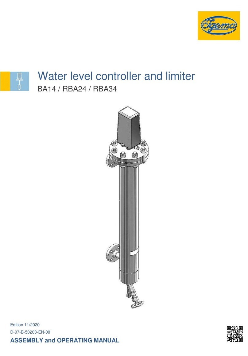
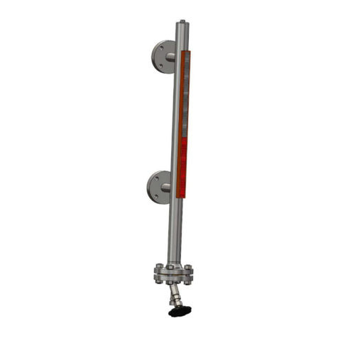
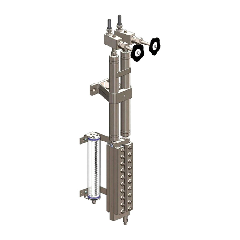
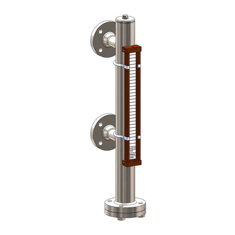
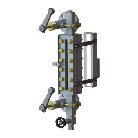
Igema TG200 Owner's manual

Edition 04/2021
D-03-B-51284-EN-02
INSTALLATION AND OPERATION INSTRUCTION
TG200 with LEDSecure Slim
Transparent level gauge

2
Product philosophy
Thank you for placing your trust in IGEMA and deciding in favour of one of our
high-quality products.
For more than 100 years, measuring and control systems have been developed,
produced and sold worldwide under the IGEMA brand name.
“Steam is our passion” and we offer you the entire programme for the safe and
economic operation of your plants, especially in the steam and condensate sector.
Please read the installation and operating instructions carefully to ensure a safe and
reliable operation.
In addition to the information on installation and operation, you will also find important
information on maintenance, care, safety and value retention of your measuring and
control system.

3
Table of contents
1. Important safety instructions.............................................................................6
1.1 Symbols used in these instructions...................................................................6
1.2 Intended use of the device................................................................................7
1.3 Safety at work...................................................................................................8
1.4 Safety instructions for this device......................................................................9
1.5 Exclusion of liability...........................................................................................9
2. Contents of packing............................................................................................9
3. Important information.......................................................................................10
3.1 Intended use...................................................................................................10
4. Explanations......................................................................................................10
4.1 System description..........................................................................................10
4.2 Function..........................................................................................................10
4.3 Versions..........................................................................................................10
5. Technical data ...................................................................................................12
5.1 Dimensions.....................................................................................................12
5.2 Type of connection..........................................................................................14
5.3 Materials .........................................................................................................14
5.4 Application limits .............................................................................................14
5.5 Corrosion resistance.......................................................................................14
5.6 Rating plate / Marking.....................................................................................14
6. Construction......................................................................................................15

4
Table of contents
7. Assembly...........................................................................................................16
7.1 Version with flange..........................................................................................16
7.2 Version with welding end ................................................................................16
7.3 Heat treatment of weldseams .........................................................................16
7.4 Drain piping.....................................................................................................16
7.5 Illumination device ..........................................................................................16
8. Commissioning .................................................................................................17
8.1 Before commissioning.....................................................................................17
8.2 Commissioning of unit together with the boiler................................................18
8.2 Commissioning of the unit when the boiler is under pressure and at
temperature.....................................................................................................18
9. Maintenance ......................................................................................................19
9.1 Leakage..........................................................................................................20
9.2 Cleaning of mica shields.................................................................................20
9.3 Cleaning and purging of level gauge...............................................................21
9.4 Exchange of mica shields ...............................................................................21
9.5 Assembly ........................................................................................................22
9.6 Tightening torques ..........................................................................................22
10. Shutoff valve......................................................................................................22
10.1 Allgemeine Hinweise und Arbeitshinweise..................................................22
10.2 Functional principle.....................................................................................22
10.3 Self-closing ball safety function...................................................................23

5
Table of contents
10.4 Construction................................................................................................24
10.5 Commissioning...........................................................................................27
10.6 Maintenance...............................................................................................28
10.7 Assembly....................................................................................................29
11. Drain valve.........................................................................................................29
11.1 Information..................................................................................................29
11.2 Functional principle.....................................................................................29
11.3 Assembly....................................................................................................30
11.4 Commissioning...........................................................................................30
11.5 Maintenance...............................................................................................31
12. Case of damage.................................................................................................32
13. Spare parts ........................................................................................................32
13.1 Transparent level gauge.............................................................................32
13.2 Shutoff valve...............................................................................................35
13.3 Drain valve..................................................................................................35
14. Decommissioning .............................................................................................36
14.1 Disposal......................................................................................................36
15. Manufacturer´s declaration..............................................................................37

6
1. Important safety instructions
KEEP THESE INSTALLATION AND OPERATING INSTRUCTIONS IN A SAFE PLACE!
Commissioning as well as maintenance and repair work may only be carried out by qualified
persons in compliance with the installation instructions given in this operating manual. The
correct installation, commissioning, maintenance and operation of the device presupposes that
the person in charge is familiar with measurement and control systems and complies with the
general installation and safety instructions. In addition, the correct and intended use of tools
and the handling of safety devices must be ensured. Unqualified personsmust not be assigned
the above tasks!
IGEMA GmbH accepts no liability for damage to property or personal injury caused by
unqualified persons or by failure to observe these installation and operating instructions. If no
sufficiently qualified person can be found, IGEMA GmbH can be commissioned with the
installation/maintenance.
1.1 Symbols used in these instructions
In the following installation and operating instructions, safety instructions are marked with the
following symbols:
Danger
This symbol and signal word refer to a potentially
hazardous situation which could result in death or
injuries if ignored.
Caution electrical voltage
This symbol and signal word indicate live parts
with an immediate danger of death from electric
shock.
Caution hot
This symbol with a signal word indicates a
potentially hazardous situation that can result in
severe burns and scalds all over the body.

7
Caution
This symbol and signal word refer to a potentially
hazardous situation which could result in
personal injury, property and environmental
damage if ignored.
Caution
This symbol and signal word refer to a potentially
hazardous situation which couldresult in damage
to the equipment if ignored.
Info
This symbol indicates useful information and
recommendations as well as measures that will
prolong the value of your measuring and control
system.
1.2 Intended use of the device
Use these installation and operating instructions, the identification on the rating
plate (see 5.6) and the technical data sheet to check whether the device is
suitable for the intended use/application. The device complies with the
requirements of the European Pressure Equipment Directive 2014/68/EU.
The device may only be used to indicate fill levels on containers.
The maximum values of the pressure and temperature range of the device must be checked
before installation. If the maximum allowable operating values of the device are lower than
those of the system on which it is to be installed, protective instruments for the device, such
as pressure reducers or similar, must be provided to avoid limit situations. The device may
only be used in accordance with the information in these installation and operating instructions
or for the parameters and applications agreed in the supply contract. (see rating plate, 5.6)
The operator of the direct water level indicator is obliged to familiarise himself on the
compatibility of the medium and the device. In case of doubt, contact the relevant installation
manager or site manager.
The correct installation position, alignment and flow direction of the device must be observed!
Before installing the IGEMA product on boilers or containers, it is essential to remove all
protective covers and, if necessary, the protective film from rating plates and sight glasses.
Caution

8
1.3 Safety at work
Before installation or carrying out maintenance work on the device, safe access
must be ensured and a secure working area with sufficient lighting must be
defined and marked out. Always use lifting equipment for heavy loads!
Before starting any work, carefully check which liquids or gases are or have been in the
pipeline. (flammable substances, irritating substances,substances hazardous tohealth) When
opening or dismantling the device, residues of the medium can escape. Subsequent fumes
are also possible in unpressurized and cold systems. Use designated PPE such as safety
goggles and respiratory protection!
Special attention must be paid to the condition of the environment around the installation or
maintenance site. Be aware of e.g.: potentially explosive atmospheres, lack of oxygen in tanks
and pits, dangerous gases/liquids, extremetemperatures, hot surfaces,fire hazard (e.g. during
welding) and moving machine and system components. Protect yourself from excessive noise
by taking the required protective measures.
For all maintenance work or new installations, on new or existing boilers or vessels, it is
imperative to check that the boiler or vessel has been depressurised andthat the pressure has
been safely reduced to atmospheric pressure. In principle, no system should be regarded as
unpressurized even if indicated by pressure measuring devices such as pressure gauges or
sensors. When releasing the pressure, make sure that no persons are in the release area.
Carefully check whether you and/or other persons in the vicinity need PPE to protect yourself
from external influences such as high and low temperatures, radiation, noise, danger to eyes,
loose objects that can fall down or chemicals.
There is always a risk of injury when handling large and/or heavy equipment. Observe the load
handling regulation as a minimum requirement for working with loads. Avoid handling the
device with your own physical force, e.g. by lifting, pulling, carrying, pushing or supporting it,
especially to prevent back injuries. Use lifting equipment to move heavy and bulky equipment
in accordance with Article 1, Section 2 of the German Load Handling Regulation
(LasthandhabV).
Under normal operating conditions the surface of the device can become very
hot! Under the maximum operating conditions, the surface temperature can
exceed 350°C. After shutting off or, if necessary, shutting down the boiler, wait
until the temperature has normalized to room level. To avoid the risk of burns
and scalds, always use PPE including safety goggles!
Danger
Caution
hot!

9
1.4 Safety instructions for this device
These installation and operating instructions are an integral part of the device
and must be forwarded to the responsible departments "Goods inward,
Transport, Installation, Commissioning and Maintenance". They must be kept in
such a way that the technical staff have access to these documents at all times.
If the device is passed on to a third party, these installation and operating
instructions must also be included in the national language of the third party.
Avoid shocks and hard contact during transport, as this can lead to damage. During
intermediate storage, the device must be kept dry and secured against damage.
When servicing the unit, make sure to use sharp-edged internal parts and avoid shards of
broken glass. There is a risk of cutting hands and arms! Always wear work gloves when
changing packing, valve seat and valve plug.
For units with a dead weight of 30 kg or more, the customer must provide adequate support
(e.g. via a spring suspension device, etc.). This can be attached to the holding strap/eyelet on
the device.
When returning goods to IGEMA GmbH, the applicable safety and environmental laws
according to GGVSEB [German ordinance on the national and international carriage of
dangerous goods by road, rail, and inland waterways] must always be observed. If there are
any risks to health or the environment due to residues or the device has a mechanical defect
this must be indicated when returning the device and the necessary precautionary measures
must be taken. If the returned goods are devices that have come into contact with or contain
hazardous substances, a safety data sheet must be enclosed, and the goods must be clearly
marked. In addition, the hazardous substance must be reported to the logistics service
provider.
1.5 Exclusion of liability
IGEMA GmbH Mess- und Regelsysteme will assume no liability if the above regulations,
instructions and safety precautions are not observed and followed. If they are not expressly
listed in the installation and operating instructions, changes to an IGEMA device are carried
out at the risk of the user.
2. Contents of packing
1. The level gauge is delivered in 2 units (A and B) (see page 11)
Unit A consists of: •upper shutoff valve (2)
•mica holder (1)
•lower shutoff valve (3)
•drain valve (4)
Unit B consists of: •illumination device (6)
2. Mounting and operating instructions
Caution

10
3. Important information
The direct water level gauge is for measurement and control purposes and
must only be used to display fill levels on a tank. Here care must be taken
that pressure and temperature do not exceed the maximum limitations of
use. These can be found on the identification plate.
The operator of the direct water level gauge is responsible for the intended
use of the indicator.
With the “offset” version adequate support (e.g. by spring suspension
elements etc.) must be provided to the device at the customer’s premises.
This can be fastened to the “transport unit”.
3.1 Intended use
Transparent level gauge:
The transparent level gauge type mica is a direct water level gauge with illumination which
can be used for steam boilers and containers.
This product is in accordance to EU-directive 2014/68/EU. Applied policy acc. to DIN EN 13445
and ASME Boiler and Pressure Vessel Code. Considered regulations AD2000. Furthermore,
this product meets the requirements of the standards DIN EN 12952-7 and DIN EN 12953-6
as a plant component for large water room boilers and water tube boilers.
4. Explanations
4.1 System description
The transparent level gauge in different versions is used to detect the water level of steam
generators or containers.
4.2 Function
The level gauge works according to the physical law of the communicating tubes. The water
level is visible due to the illumination of the water-steam space from the back. In the sight
opening, the water level is visible at the interface between water and steam.
Caution
Caution
Caution

11
4.3 Versions
The transparent level gauges TG200 are available in two versions, one with a single display
length and one with offset display lengths. With the offset version, there is always at least a
26mm overlap to the opposite display length. The two variants are shown below.
Fixed connection
Swivel connection

12
5. Technical data
5.1 Dimensions
*1 Right-hand version shown
One sight opening*1
Sight openings staggered*1
Ü = overlapping

13
Schauöffnungen versetzt zweifach*1
Ü = Überdeckung
*1 Right-hand version shown
Sight openings:
Size
7
8
9
10
11
Single sight length En
260
290
320
340
380
other sizes on request n= number of sight openings
One sight opening E= En
Sight openings staggered E= nxEn - (n-1)xÜ
Size marking for several sight openings:
E
n
v
Size of sight opening
Number of sight openings
Version: v = staggered
Valves:
Valve
Type
Shutoff valve
A220, A240 / swivelable version A210, A230
Drain valve
AV250

14
5.2 Type of connection
Standard : flanges according to DIN
On request : flanges according to ASME
Welding end or Socket Welding according to DIN or ASME
5.3 Materials
Parts in contact with the medium: C steel or stainless steel according to DIN or ASME.
Pressure holding components: C steel or stainless steel according to DIN or ASME.
5.4 Application limits
5.5 Corrosion resistance
The safety of the unit is not influenced by corrosion if it is used as intended.
5.6 Rating plate / Marking
The following data are indicated on the identification plate:
* marking depending on the realization
A Date of manufacture
B Type of unit
C Max. all. pressure
D Max. all. temperature
E Nominal pressure (not listed)
F Nominal diameter
G TAG-no. (Optional)
Max. all. pressure PS
[bar]
100
200
Max. all. temperature TS
[°C]
312
367
*
IGEMA GmbH
Mess- und Regelsysteme
Antwerpener Straße 1
Germany –48163 Münster
G

15
6. Construction
Lateral connection
PS=32-200 bar
Cross section level gauge
PS=80-200 bar
At PS=32-50 bar the cover screws and holding
screws are in one row. The holding screws are
always the second from top and from bottom.
Cross section level gauge
PS=32-50 bar
(1) Mica holder (9) Mica shield
(2) Upper shutoff valve (10) Pressure plate
(3) Lower shutoff valve (11) Cover rail
(4) Drain valve (12) Hexagon nut
(5) Plug G½" (13) Stud (holding screw)
(6) Illumination (14) Hexagon nut
(7) Cover screw (15) Plug G¼" (staggered version)
(8) Sealing

16
7. Assembly
7.1 Version with flange
•Respect installation position!
•Remove protection caps from connection flanges. Caps only serve as transport
protection.
•Ensure that sealing surfaces are clean and undamaged.
•Mount transparent level gauge.
7.2 Version with welding end
•Respect installation position!
•Remove protection caps from connection flanges. Caps only serve as transport
protection.
•Assembly only by using welding process 111 and 141.
7.3 Heat treatment of weldseams
Supplementary temper tests of weldseams are not required.
7.4 Drain piping
•Close valves (D1, D2, W1, W2) after mounting.
•Mount drain piping on drain valve (4) (to be provided by the customer).
Ensure that drain piping has free outlet to atmosphere and is protected
from pressure peaks!
7.5 Illumination device
Only use the lamp in explosion-proofed rooms!
Only skilled and qualified electricians may carry out assembly and
connection of the lamps!
Never insulate illumination devices!
Mount the illumination device with the fixing elements on the level gauge.
Caution
Danger

17
8. Commissioning
Commissioning and maintenance must be carried out by qualified
personnel! If no sufficiently qualified person can be employed, IGEMA
GmbH can be commissioned to carry out the commissioning. In principle
IGEMA GmbH recommends commissioning the indicator at the same time
as the boiler (item 8.2). If it is not possible to commission the indicator
according to item 8.2, the indicator can be commissioned with the boiler under pressure
and temperature (item 8.3)
All liquid level gauges are subjected to 100% pressure testing before delivery. In individual
cases, material settling may occur during transport, longer storage or during assembly. All
screw connections must therefore be checked for tight fit and appropriate torque (see following
text).
8.1 Before commissioning
Before commissioning, the indicator must be checked for damage and all screw connections
must be checked for tightening torque Md max according to the table (see item 9.6)!
Tightening sequence to be observed for the cover rails is presented
below!
Non-compliance may result in leakage, glass and mica break.
The following tightening sequence must be ensured at the cover rails (drawing below). Non-
compliance can lead to leaks, which are not covered by the warranty. Tighten the screw
connection to the tightening torque Md max. according to the table (see item 9.6).
uneven number even number screw rows
At the latest 24 h after commissioning, the screw connections must be checked and tightened
max. again with the torques specified above in the listed tightening sequence Mdmax (see item
9.6)! This should be repeated until the bolts permanently hold the specified torques.
Danger
Caution

18
The union nuts of the valves must be tightened so that no leakage occurs at the spindle and
the handwheel / hand lever can still be turned.
Note!
After commissioning, slight leaks can occur in the valves, but these will reappear
after a short time due to temperature and pressure.
8.2 Commissioning of unit together with the boiler
First make sure that the drain valve (18) is closed. Then open the shut-off
valves (D1, D2, W1, W2) to the stop. The boiler can now be commissioned
with the indicator. After commissioning the indicator must be checked for
function and leakage. The specified torques and the described tightening
sequence (item 9.6) apply.
Check specifications of material, pressure and temperature!
8.3 Commissioning of the unit when the boiler is under pressure and at
temperature
During such procedure the level indicator shall be isolated completely from the
connected tank. Initially, both (upper-D2 and lower-W2) shut off valves should
be close. Next, the drain valve (D4) shall open. The individual carrying out the
commissioning should wait until temperature and pressure in the level indicator
is attained. After, the temperature and pressure in the level indicator is stabilized
commissioning can takeplace. After finishing thecommissioning procedure,the D2 valve shall
be open slightly (approximately 5-minute position) to allow a restricted amount of steam to
pass through the level gauge and heat up the entire assembly at about the connected tank
temperature. That is to avoid thermal shok from rapide changes in material temperature. When
the gauge temperature is attained to the tank´s operating temperature the drain valve (4) shall
be completely closed. The D2 valve shall then open completely. As the shut-off valves are
quick closing type, it shall be opoen slowly in order to not allow an excessive amount of steam
entering the level indicator suddenly and create shoks that might lead to fatigue. Afre the level
indicator is fill with steam the responsible individual shall wait until pressure is stabilized and
condensation will start to form. Then W2 valve shall be slowly opened to allow water to pass.
The presure in the level indicator shall be stabilized before opening the W2 valve, otherwise
ther is a risk of flushing during opening of the W2 valve that can cause damages to the valve
as well as the level indicator. When the water level falls to the expencted NWL, both valves
shall be ensured that open and to be checked for leaking.
Info
Caution
Caution
hot!

19
9. Maintenance
It is assumed that the person charged with the maintenance tasks is fully conversant with
measurement and control systems. Untrained persons must not carry out maintenance work!
If there is no adequately qualified person available, IGEMAGmbH can be brought in to service
your measurement and control system.
When replacing components, it must be ensured that only original IGEMA GmbH parts
are used.
Any warranty is void if components from other manufacturers are used.
Preventive Maintenance
The following points should be observed to maximize gauge life:
Proper cleaning and maintenance of level gauges in steam service is vital for enhanced
performance and service life. The gaskets and mica shields shall always be replaced during
maintenance, even if they appear to be in perfect condition. Gaskets relax and can harden
over time while defects in mica (i.e., chips or scratches) become points of high stress
concentration. Even with no visible defects, a used glass has surface stresses induced from
the original assembly and pressurization of the gauge. If reassembled, the gaskets and
sealing surfaces will apply new stresses, which are likely to break the mica either during
assembly or when the gauge is pressurized.
Therefore, new mica is always required. The gauge glass must be kept clean to ensure the
visible water level in the chamber accurately represents the water level in the boiler.
The user must determine upon evaluation of his or her own operating experience an
appropriate maintenance schedule necessary for the specific application. Note that the
frequency and method of blow-down/purging may affect service life and performance of glass
level gauges. Realistic maintenance schedules can only be determined with full knowledge of
the services and application situation involved.

20
9.1 Leakage
Re-tighten corresponding screws in case of leakages.
Replace sealing if necessary and check sealing surface.
Severe burns and scalding’s on the whole body are possible!
Before replacing the sealings, level gauge must be pressureless and
empty!
Leakage
•In case of leakage, close upper and lower shutoff valve (2, 3) and slowly open drain valve
(4) a little.
•Fully open drain valve if noise of escaping pressure is no longer audible.
•Tighten the combination cover/holding screws up to PS=50 bar (7, 13) as well as the
cover screws starting from PS=80 bar (13) in several steps using successively opposite
diagonal (see table chapter 8.1) tightening from top to bottom (see table item 9.6) until
tightening torque Mdmax is reached.
9.2 Cleaning of mica shields
During first commissioning or re-commissioning of a boiler, oil and grease residues can
deposit on the inside of the mica shields.
In such cases:
•Close shutoff valves (2, 3).
•Open drain valve (4). Wait until temperature and pressure are back to ambient.
•Remove plug (5, 15) and clean mica shields as well as channel inside of the
indicator body with a circular brush.
Danger
Table of contents
Other Igema Measuring Instrument manuals
Popular Measuring Instrument manuals by other brands

Trotec
Trotec BP17 quick start guide

Endress+Hauser
Endress+Hauser FQG60 Technical information & operating instructions

2B Technologies
2B Technologies 211 quick start guide

DOLD
DOLD RN 5897/240 Translation of the original instructions

Futech
Futech DISTY 120RC instruction manual

Aquaread
Aquaread Aquaprobe AP-7000 instruction manual