Igema DLT2 User manual

Edition 11/2020
D-08-B-51053-EN-00
INSTALLATION- AND OPERATING INSTRUCTION
DLT2 / DLT3 with overfill protection
for use with the level probe: EC 8
Continuous Water Level Transmitter

2
Product philosophy
Thank you for placing your trust in IGEMA and deciding in favour of one of our
high-quality products.
For more than 100 years, measuring and control systems have been developed,
produced and sold worldwide under the IGEMA brand name.
“Steam is our passion” and we offer you the entire programme for the safe and
economic operation of your plants, especially in the steam and condensate sector.
Please read the installation and operating instructions carefully to ensure a safe and
reliable operation.
In addition to the information on installation and operation, you will also find important
information on maintenance, care, safety and value retention of your measuring and
control system.

3
Table of contents
1. Important safety instructions.............................................................................5
1.1 Symbols used in these instructions...................................................................5
1.2 Intended use of the device................................................................................6
1.3 Safety at work ...................................................................................................7
1.4 Safety instructions for this device......................................................................8
1.5 Exclusion of liability...........................................................................................8
2. Contents of the packaging.................................................................................9
3. Proper use ...........................................................................................................9
4. System Description.............................................................................................9
4.1 Function............................................................................................................9
4.2 Control unit......................................................................................................10
4.3 Error messages...............................................................................................11
5. Assembly and Installation................................................................................11
5.1 Installation dimensions and descriptions.........................................................11
5.2 Installation.......................................................................................................12
5.3 Electrical connection.......................................................................................12
5.3.1 Schematic diagram.......................................................................................13
5.3.2 Assignment plan evaluator...........................................................................13
5.3.3 Cable evaluator - probe................................................................................14
5.3.4 Connecting the probe...................................................................................14
5.3.5 Power interface 4 mA .. 20 mA.....................................................................14

4
Table of contents (cont.)
6. Configuration via menu....................................................................................15
6.1 Basics .............................................................................................................15
6.2 Diagram ..........................................................................................................15
6.3 Numerical entry...............................................................................................16
6.4 Password input - example...............................................................................16
6.5 Programming of min. and max. level...............................................................16
6.6 Programming of the overfill protection (DLT3) ................................................17
7. Technical Data...................................................................................................18
7.1 Device data.....................................................................................................18
7.2 Maximum ratings of outputs............................................................................18
7.3 Data plate........................................................................................................19
8. Fault analysis and rectification........................................................................19
9. Declaration of Conformity ................................................................................21

5
1. Important safety instructions
KEEP THESE INSTALLATION AND OPERATING INSTRUCTIONS IN A SAFE PLACE!
Commissioning as well as maintenance and repair work may only be carried out by qualified
persons in compliance with the installation instructions given in this operating manual. The
correct installation, commissioning, maintenance and operation of the device presupposes that
the person in charge is familiar with measurement and control systems and complies with the
general installation and safety instructions. In addition, the correct and intended use of tools
and the handling of safety devices must be ensured. Unqualified personsmust not be assigned
the above tasks!
IGEMA GmbH accepts no liability for damage to property or personal injury caused by
unqualified persons or by failure to observe these installation and operating instructions. If no
sufficiently qualified person can be found, IGEMA GmbH can be commissioned with the
installation/maintenance.
1.1 Symbols used in these instructions
In the following installation and operating instructions, safety instructions are marked with the
following symbols:
Danger
This symbol and signal word refer to a potentially
hazardous situation which could result in death or
injuries if ignored.
Caution electrical voltage
This symbol and signal word indicate live parts
with an immediate danger of death from electric
shock.
Caution hot
This symbol with a signal word indicates a
potentially hazardous situation that can result in
severe burns and scalds all over the body.

6
Caution
This symbol and signal word refer to a potentially
hazardous situation which could result in
personal injury, property and environmental
damage if ignored.
Caution
This symbol and signal word refer to a potentially
hazardous situation which couldresult in damage
to the equipment if ignored.
Info
This symbol indicates useful information and
recommendations as well as measures that will
prolong the value of your measuring and control
system.
1.2 Intended use of the device
Use these installation and operating instructions, the identification on the data
plate (see 7.3) and the technical data sheet to check whether the device is
suitable for the intended use/application. The device complies with the
requirements of the European Pressure Equipment Directive 2014/68/EU.
The device may only be used to indicate fill levels on containers.
The maximum values of the pressure and temperature range of the device must be checked
before installation. If the maximum allowable operating values of the device are lower than
those of the system on which it is to be installed, protective instruments for the device, such
as pressure reducers or similar, must be provided to avoid limit situations. The device may
only be used in accordance with the information in these installation and operating instructions
or for the parameters and applications agreed in the supply contract. (see data plate, 7.3) The
operator of the facility is obliged to familiarise himself on the compatibility of the medium and
the device. In case of doubt, contact the relevant installation manager or site manager.
The correct installation position, alignment and flow direction of the device must be observed!
Before installing the IGEMA product on boilers or containers, it is essential to remove all
protective covers and, if necessary, the protective film from data plates.
Caution
7
1.3 Safety at work
Before installation or carrying out maintenance work on the device, safe access
must be ensured and a secure working area with sufficient lighting must be
defined and marked out. Always use lifting equipment for heavy loads!
Before starting any work, carefully check which liquids or gases are or have been in the
pipeline. (flammable substances, irritating substances,substances hazardous to health) When
opening or dismantling the device, residues of the medium can escape. Subsequent fumes
are also possible in unpressurized and cold systems. Use designated PPE such as safety
goggles and respiratory protection!
Special attention must be paid to the condition of the environment around the installation or
maintenance site. Be aware of e.g.: potentially explosive atmospheres, lack of oxygen in tanks
and pits, dangerous gases/liquids, extremetemperatures, hot surfaces,fire hazard (e.g. during
welding) and moving machine and system components. Protect yourself from excessive noise
by taking the required protective measures.
For all maintenance work or new installations, on new or existing boilers or vessels, it is
imperative to check thatthe boiler or vessel has been depressurised and that the pressure has
been safely reduced to atmospheric pressure. In principle, no system should be regarded as
unpressurized even if indicated by pressure measuring devices such as pressure gauges or
sensors. When releasing the pressure, make sure that no persons are in the release area.
Carefully check whether you and/or other persons in the vicinity need PPE to protect yourself
from external influences such as high and low temperatures, radiation, noise, danger to eyes,
loose objects that can fall down or chemicals.
There is always a risk of injury when handling large and/or heavy equipment. Observe the load
handling regulation as a minimum requirement for working with loads. Avoid handling the
device with your own physical force, e.g. by lifting, pulling, carrying, pushing or supporting it,
especially to prevent back injuries. Use lifting equipment to move heavy and bulky equipment
in accordance with Article 1, Section 2 of the German Load Handling Regulation
(LasthandhabV).
Under normal operating conditions the surface of the device can become very
hot! Under the maximum operating conditions, the surface temperature can
reach 240°C. After shutting off or, if necessary, shutting down the boiler, wait
until the temperature has normalized to room level. To avoid the risk of burns
and scalds, always use PPE including safety goggles!
Danger
Caution
hot!

8
1.4 Safety instructions for this device
These installation and operating instructions are an integral part of the device
and must be forwarded to the responsible departments "Goods inward,
Transport, Installation, Commissioning and Maintenance". They must be kept in
such a way that the technical staff have access to these documents at all times.
If the device is passed on to a third party, these installation and operating
instructions must also be included in the national language of the third party.
Avoid shocks and hard contact during transport, as this can lead to damage. During
intermediate storage, the device must be kept dry and secured against damage.
When servicing the unit, make sure to check for damage. There is a risk of cutting hands and
arms!
When returning goods to IGEMA GmbH, the applicable safety and environmental laws
according to GGVSEB [German ordinance on the national and international carriage of
dangerous goods by road, rail, and inland waterways] must always be observed. If there are
any risks to health or the environment due to residues or the device has a mechanical defect
this must be indicated when returning the device and the necessary precautionary measures
must be taken. If the returned goods are devices that have come into contact with or contain
hazardous substances, a safety data sheet must be enclosed, and the goods must be clearly
marked. In addition, the hazardous substance must be reported to the logistics service
provider.
1.5 Exclusion of liability
IGEMA GmbH Mess- und Regelsysteme will assume no liability if the above regulations,
instructions and safety precautions are not observed and followed. If they are not expressly
listed in the installation and operating instructions, changes to an IGEMA device are carried
out at the risk of the user.
Caution

9
2. Contents of the packaging
1 controller DLT2 or DLT3
1 set of installation and operating instructions
3. Proper use
The DLT2/DLT3 continuous level transmitter is intended for use in combination with the EC 8
level probe as level transmitter for the output of an output current proportional to the fill level
in the boiler (4 mA .. 20 mA).
At the DLT3 an overfill protection according to EN 12953-6 can be activated.
The requirements of EU Directive 2014/68/EU, of the standards EN 61326-1, EN 61010-1,
EN13445-1, EN 12952-11 and EN 12953-9 have been taken into account.
The DLT2/DLT3 has been specially developed for use in steam boilers or condensate tanks.
Measuring the water level is carried out via the EC 8 probe (see corresponding assembly and
operating instructions) which is fitted in the boiler or mounting flange.
The device does not have a safety function and must not be used for safety-related functions
(limiter).
The DLT2/DLT3, as also the EC 8 probe, carries out periodic self-testing.
4. System Description
4.1 Function
The DLT2/DLT3 continuous level transmitter works in conjunction with the IGEMA EC 8 level
probe on the basis of the capacitive fill level method of measurement.
The capacity of the condenser from measuring electrode, measuring electrode protective
tube and the stacked dielectric formed of fluid and steam changes with each change of the
fluid level in the tank. The IGEMA EC 8 measuring probe carries out the measurement of this
capacity continuously by means of a high-frequency measurement signal and transfers the
result to the DLT2/DLT3.
The DLT2/DLT3 evaluates the measurement signal and outputs the analogue current signal
4 mA .. 20 mA corresponding to the level.
10
DLT3:
An overfill protection can be activated. Then a fill-level-limit (e.g. 70%) and a value for the
return to normal operation (e.g. 65%) must be programmed.
The controller supplies the level probe, which can be fitted in the boiler, and evaluates its
signal.
It is expected that because of the non-linear boiler geometry the fill level
(water quantity / volume) does not behave in a linear way to the fill depth
/ fill level!
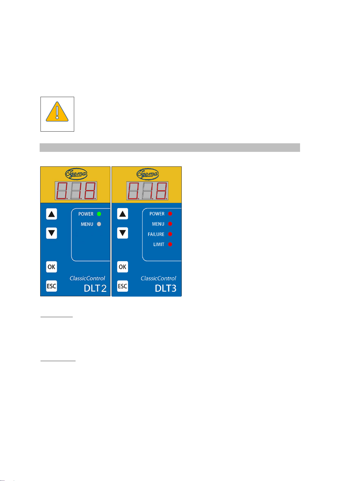
4.2 Control unit
•Seven segment display;
•4 control LEDs, arranged on the right
vertically;
•4 control buttons, arranged on the left
vertically;
At DLT2 + 3:
LED 1 (green) POWER flashes if power supply of controller or -
probe is faulty
LED 2 (yellow) MENU flashes in menu mode
Only at DLT3:
LED 3 (rot) FAILURE lights up if the device detects an electronics failure
LED 4 (grün) LIMIT lights up if overfill level is exceeded
When the controller and the probe are working correctly, the fill level in % of the range set appears in
the display: e.g. 018 (18%).
Fill levels above the two calibration points (0% and 100%) are still displayed in certain limits. The
4 mA .. 20 mA output follows the fill level / display, however only up to a value of 2.4 mA or 21.5 mA.
Further out of range values are no longer represented.
Caution

11
4.3 Error messages
In the 7-segment display, errors of the evaluator and probe are shown flashing, number-coded
and 3-digit.
In the event of any error, the relay (contacts 3, 4, 5) goes into the safe, currentless state
(contacts 3 - 4 closed) (see 5.3.2). The current output can be routed via this or an error
signal can be connected.
In the event of an error, the 4 mA .. 20 mA output jumps to 0 mA within less than 3 s
For analysis and troubleshooting see Chap. 8.
5. Assembly and Installation
The device is supplied in a plastic plug-in housing for fitting into switch cabinets. The housing
is designed for quick fitting with a spring catch for the DIN EN 50022 standard 35 mm carrier
rail and for screw fixing on a mounting plate.
5.1 Installation dimensions and descriptions
Base Front view Side view
with connecting terminals
1 Screws for quick fastening with spring catch
2 Holes, ø 4.3 mm
3 Fixing screws
4 Quick fastening with spring catch
5 Base
6 Cable feedthrough
7 Hood

12
5.2 Installation
Ensure protection class in accordance with current regulations
- With quick fastening with spring catch for standard DIN EN 50022 35 mm carrier rail
Fix device on standard carrier rail by means of the quick fastening with spring catch (4).
Release fixing screws (3) and pull hood (7) from base (5).
- Without quick fastening with spring catch
Release fixing screws (3) and pull hood (7) from base (5).
Release screws (1) and remove snap fastening (4). Drill through the marked point (2) in
the base (5) with ø 4.3 mm drill bit.
Fit holder (5) on base plate with two M4 screws.
5.3 Electrical connection
The terminal strip of the device is live during operation!!
Before working on the device, disconnect it from the power supply!!
The device must be protected mains-side by the operator with a max. T M
2A fuse!
If inductive consumers are connected, voltage peaks occur when
switching off. For this reason, connected inductive consumers (e.g.
contactor) must be provided additionally with an RC circuit: e.g. 0.1µF /
100Ω.
Danger
Danger
Danger
13
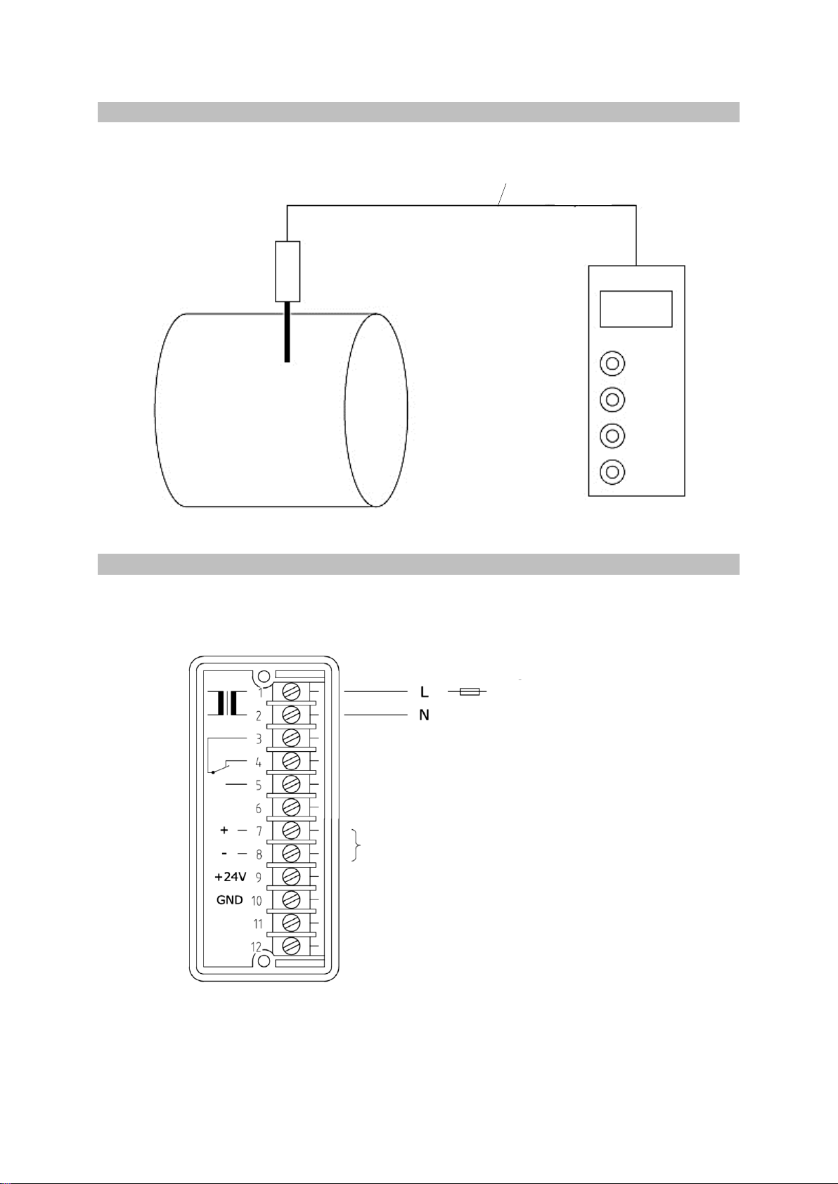
5.3.1 Schematic diagram
Steam boiler with probe with probe electronics Evaluation device
4-core lead (supply and data)
5.3.2 Assignment plan evaluator
In normal operating condition relay contacts 3 and 5 (error signalling OFF / no overfill) are
closed.
Extra relay (signalling of failure and overfill
protection [DLT3])
4mA .. 20mA not galvanically insulated
Probe connection
max. T M 2A
to be attached by the operator
CANH
CANL
}
}
DLT2/DLT3

14
GDME 3011 4-polig
5.3.3 Cable evaluator - probe
For the cable, a 4-core, twisted, shielded cable (4 x 0.5mm2 or 4 x 0.75mm2) must be used.
The side for connection to the evaluator must be assembled with end sleeves and the side for
connection to the probe with a socket (GDME 3011 4-pole).
The shield is to be fitted over a large area in the distribution cabinet on the earthing point.
Connection layout:
Evaluator Socket
9 +24V 3
10 GND ⚫
11 CANH 1
12 CANL 2
The total length of the lead must be a maximum of 250m.
When installing care must be taken that, depending on the cable used, the
UV protection is ensured on the installation side if necessary.
The cable must not come into contact with heat-conducting parts.
5.3.4 Connecting the probe
The probe is equipped with a plug connector (GSP 4-pole). It is connected to the evaluator via
the cable.
5.3.5 Power interface 4 mA .. 20 mA
For the 4 mA .. 20 mA power interface a shielded data line (e.g. LIYCY 0.5mm2) is to be
used.
The load may be max. 500Ω.
1 CANH
2 CANL
3 +24V
⚫GND
Caution

15
6. Configuration via menu
6.1 Basics
The menu of the DLT2/DLT3 is divided into two main levels:
Main level 1 | Main level 2
The menu is brought up by pressing the “OK” key. While the operator is in the configuration
menu, the associated yellow LED flashes or lights up.
With the “▲” or “▼” keys you can choose between the menu items of the respective level.
By pressing the “OK” key you will get to the next level down or confirm the input.
By pressing the “ESC” key you can get to the next level up or out of the menu without the
current entry being saved (with OK confirmed entries are already saved and remain so).
Automatic menus exit after 2 minutes if no key operation is carried out (cf. “ESC“).
6.2 Diagram
| --- 1. ---
| - 1.1. |- Temperature of the probe
| --- 2.---
| - 2.1. |- Password input
| --- |----- After valid password input ------------------
| - 2.2. |- Programming of the min. level
| - 2.3. |- Programming of the max. level
| - 2.4. |- Programming of the damping*
| - 2.5. |- Tendency display**
Nur DLT3:
| - 2.6. |- Activation Overfill protection: 0 0 1 Overfill protection activ
| - 2.7. |- Return level (%)
| - 2.8. |- Overfill limit level (%) / LIMIT
* The damping is a sliding mean value from the most recent measurements. The
number can be selected from the range of 3 –30 values. The factory setting is
5 values. The measurement frequency is approx. 1 measurement/s.
On putting into operation please check setting.
** The tendency display shows a numerical value (e.g. 2 5. 1) ) which becomes
smaller with rising fill level. It can be used for example to check whether the
probe is immersed in the water.
The password is: 123 (The password is only for protecting the device
from unwanted changes. It offers no protection from malicious changes.)
Caution

16
6.3 Numerical entry
The digit in the segment where the dot is flashing can be changed by the keys “▲” und “▼”.
The desired number is confirmed by “OK”. Then the next place (segment with flashing dot) can
be entered.
For multi-digit numbers the numbers move to the left and, if need be, out of the display.
6.4 Password input - example
Under the menu item 2.1. after confirmation with “OK” a “0 0. 0” appears.
Now in this example we enter the password 123 . It starts in the middle. The middle digit can
be changed and this is signalled by the flashing dot. With the “▲” key the 1. is selected. This
is confirmed with “OK”.
Display: 1 0. 0
The decimal point of the middle digit continues to flash. Here again with “▲” you enter the next
digit of the password (2) and confirm. Now on the display you will see a 1 2 0. and the right
decimal point flashes. The grey field is the visible area of the display
Display: 120.
The 3rd digit is a 3. It is set with “▲” and confirmed with “OK”.
This completes the input. You are again in the corresponding submenu. The other submenu
items are now enabled.
6.5 Programming of min. and max. level
For programming the minimum or maximum levels it is necessary to move
to the fill level in the boiler (note thermal linear expansion!).
Go to the first fill level. It is unimportant whether you start with the min. or max. level.
Bring up the menu on the evaluator by pressing “OK”. Select main menu 2. with the “▲” or “▼”
keys and press the “OK” button twice. You are now in menu item 2.1.. Here enter the password
“123” as in the description in Chap. 6.4.
Select the corresponding menu item (2.2. or 2.3.) for the fill level reached using the “▲” or “▼”
keys and press “OK”.
Wait the duration of the damping (see menu 2.4.) and then press the “OK” button.
Go to the other fill level and repeat the programming.
The measuring range can be individually set almost (Y-100) over the whole measuring
probe length whereby the smallest permissible measuring range is 50 mm (see Installation
and Operating Instructions EC 8).
The smallest permissible distance between the two limit levels is 50mm!
On changes to one limit level it is sufficient to move to it and to program
the corresponding fill level (0% or 100%).
Caution
Caution

17
6.6 Programming of the overfill protection (DLT3)
The overfill level cannot be below the level of the return value!
The return value cannot be above the overfill level!
Activate the programming menu by pressing „OK“. Switch to main menu 2. via the buttons „▲“
or „▼“ and press button „OK“ 2 times. You have reached menu item 2.1.. Enter password (123)
as per chap. 6.4.
Switch to menu item “Activation Overfill protection” (2.6.) via the buttons „▲“ or „▼“ and press
„OK“.
Change the value „0 0 0.” to „0 0 1.” (buttons „▲“ or „▼“) and press „OK“.
Choose menu item “Overfill limit level (%) / LIMIT” (2.8.) via the buttons „▲“ or „▼“ and press
„OK“.
Display: → 0X.XX(The grey area is the viewable area of the display / X means a value of
0-9)
The buttons „▲“ (value of return level) or „▼“ (100%) are a quick way to set the starting point
for the LIMIT. After pressing „OK“ the display is 0XX.X .
Enter the desired LIMIT value e.g. „075” for 75% and press „OK“. You reach the last digit via
„OK“.
Choose menu item „return level (%)“ (2.7.) via the buttons „▲“ or „▼“ and press „OK“.
Display: → 0X.XX (The grey area is the viewable area of the display / X means a value of
0-9)
The buttons „▲“ (0%) or „▼“ (value of overfill limit) are a quick way to set the starting point for
the return level. After pressing „OK“ the display is 0XX.X .
Enter the desired return level e.g. „070” for 70% and press „OK“. You reach the last digit via
„OK“.
The return level is the value at which the DLT3 return to normal operation
and thus the output relay returns into the normal operation mode (relay
contacts 3 and 5 closed).
Caution
Caution
18
7. Technical Data
7.1 Device data
Manufacture in accordance with: EU-Directive 2014/68/EU
applied standards: EN 13445-1, EN 61326-1, EN 61010-1
EN 12952-11, EN 12953- 9
Other Technical Regulations: Water level 100 - dated February 2010
Supply voltage: 230V AC (-15% +10%), 50/60Hz
Power consumption: 3VA
Data exchange: digital measurement value output
Electrical connection: 12-pole Screw terminal strip
Protection class: IP40 in accordance with DIN EN 60529
(protection class IP54 is to be ensured in the boiler area)
Device fuse: 63 mA/T
Allowable ambient temperature: 0°C bis 55°C
Supply voltage probe: short-circuit-proof, 24V / 2W
Self-test alle 3sec
Service life probe: The service life of the probe depends on the operating
conditions and state of the boiler water.
The total length of lead: max. 250m
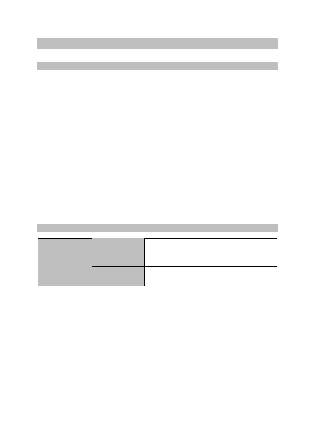
7.2 Maximum ratings of outputs
Power interface
Output current
4 mA .. 20 mA
(not galv. insulated)
Load
max. 500 Ω
Limit and Failure
relay
Switching voltage
(max.)
250 VAC
24 VDC
Switching current
(max.)
4 A ohmic
4 A
inductive / higher loads: use contactor

19
7.3 Data plate
8. Fault analysis and rectification
The device terminal strip is live during operation!!
Before working on the device disconnect it from the mains!!
In operation various error states are indicated in the display. These error codes can be
assigned to possible causes of error with the following tables.
Evaluation device malfunctions:
Error code
Cause
Remedial Action
000
Fault in the ADC converter
Replace device
001
Malfunction of the 24-volt supply voltage of
the evaluation device
Replace device
002
Malfunction in the probe supply voltage
Check data cable for fault ;
Replace device
005
Extra relay faulty
Replace device
8.8.8.
(flashing)
Segments in display faulty
Replace device
Danger

20
Probe malfunctions:
If the probe electronics report a malfunction, this will also be displayed.
Error
code
Description
Cause
Remedial Action
102
Fault in the probe
hardware
e.g. broken cable, hardware
fault
Replace probe
103
Calibration error
0% or 100% not calibrated or
wrong way round; calibrated
measuring range too small
Repeat calibration
105
Probe temperature too
high, occurs with
Tprobe≥105°C
Ambient temperature of probe
probably too high
Heat insulation measures on
the flange must not be
carried out on the electronic
part
106
Connection problem
Fault
e.g. broken cable, connections
wrong way round
Check wiring
Every error code (except “8.8.8”) causes the extra relay to be switched off.
The 4 mA .. 20 mA output then jumps to 0 mA within under 3 s
The flashing code „120“ is active if the level limit is passed. This is not
considered an error code. The 4 mA .. 20 mA output stays at its level
equivalent value.
120
fill level exceeded
fill level above limit
reduce liquid level
This high-quality IGEMA product was designed, manufactured and tested with the
application of the QM System guidelines in accordance with DIN EN ISO 9001:2000.
If the device supplied indicates transport damage or gives cause for complaint in
spite of our final quality control please contact our SERVICE department on
telephone +49 2501 92424-0 by return.
Caution
This manual suits for next models
1
Table of contents
Popular Transmitter manuals by other brands


Definitive Technology
Definitive Technology SCW-100 owner's manual

GF Signet
GF Signet 8450-3 manual

tau
tau S-4RP Series Operation and Adjustments

NIVELCO
NIVELCO NIVOPRESS NT Series user manual

Pyle view
Pyle view PLVWGM3 supplementary guide

Sentera Controls
Sentera Controls DPD-F-1K0 Mounting and operating instructions