page 1 of 8‡ SIGNET 8450-3 Pressure Transmitter
CAUTION!
• Remove power to unit before wiring
input and output connections.
• ollow instructions carefully to avoid
personal injury.
‡ SIGNET 8450-3 Pressure Transmitter ENGLISH
Contents
1. Installation
2. Specifications
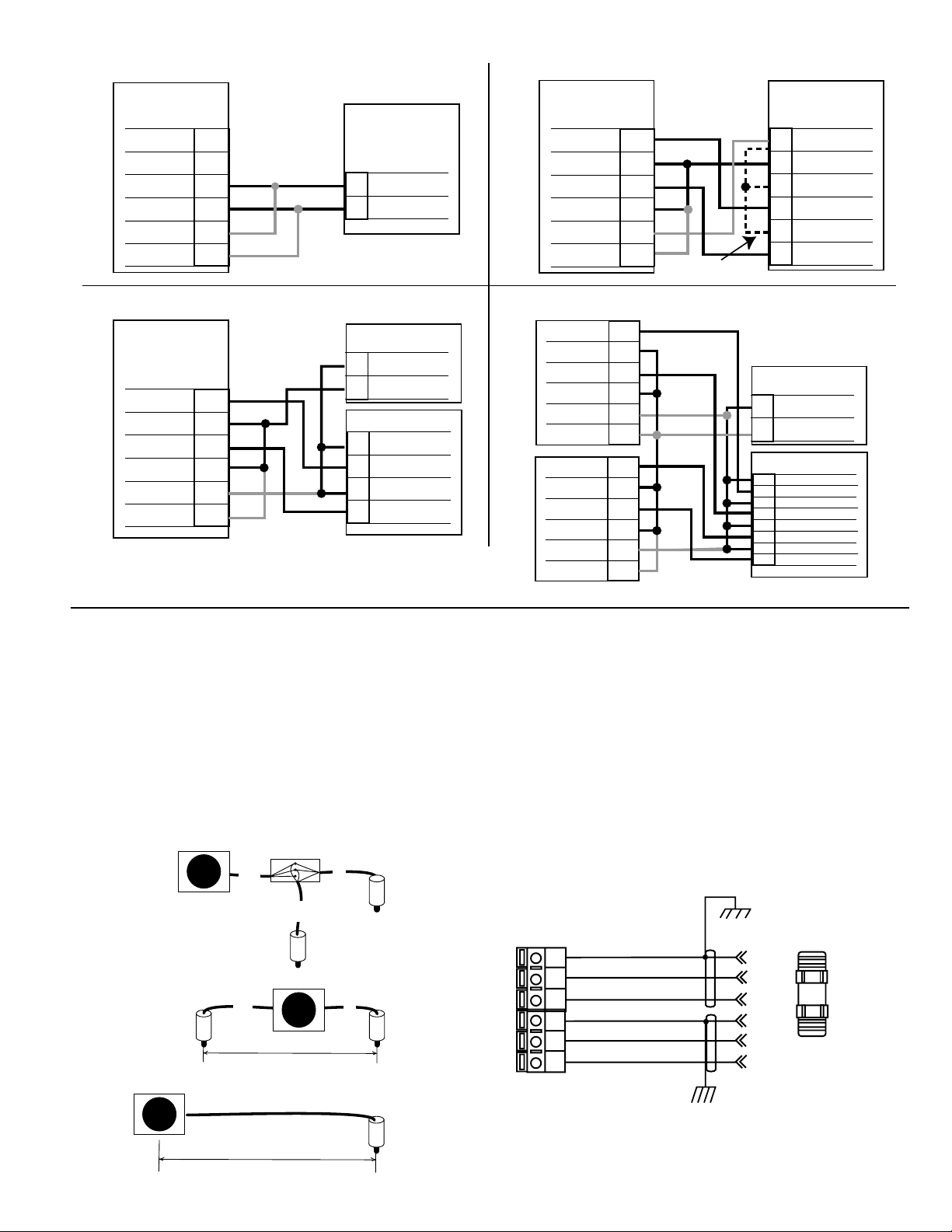
3. Electrical Connections
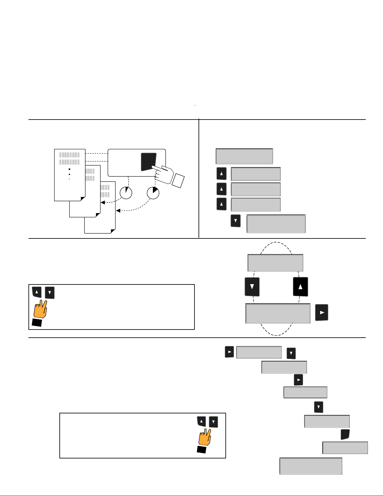
4. Menu unctions
3-8450.090-3
Pressure
Pres1: 4.5 psi
Pres2: 2.3 psi
ENTE
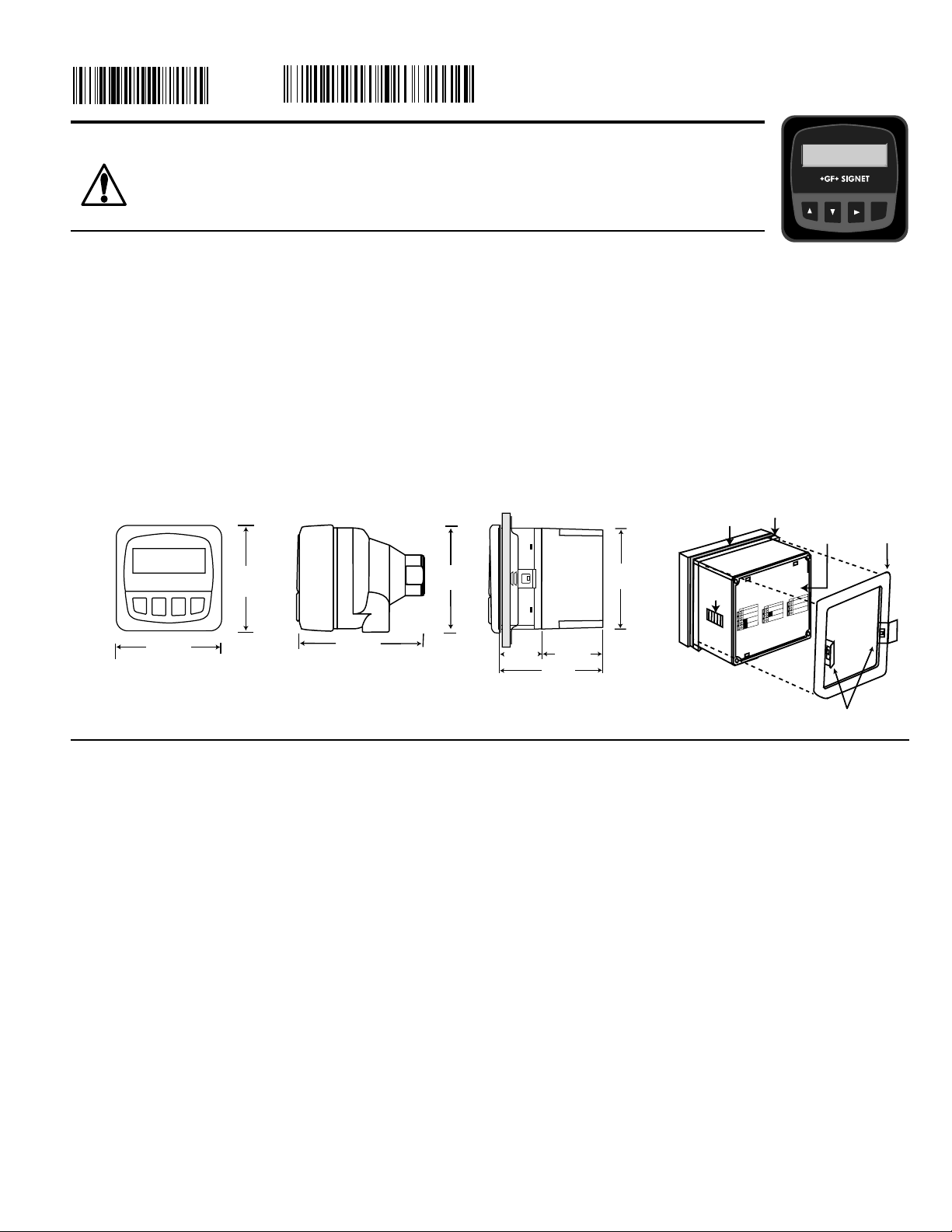
SIDE VIEW
92 mm
(3.6 in.)
97 mm
(3.8 in.)
56 mm
(2.2 in.)
41 mm
(1.6 in.
)
Optional
Rear
Cover
ield Mount Panel Mount
RONT VIEW
96 mm
(3.8 in.)
96 mm
(3.8 in.)
107 mm
(4.2 in.)
96 mm
(3.8 in.)
quick-clips
gasket panel
terminals mounting
bracket
latch
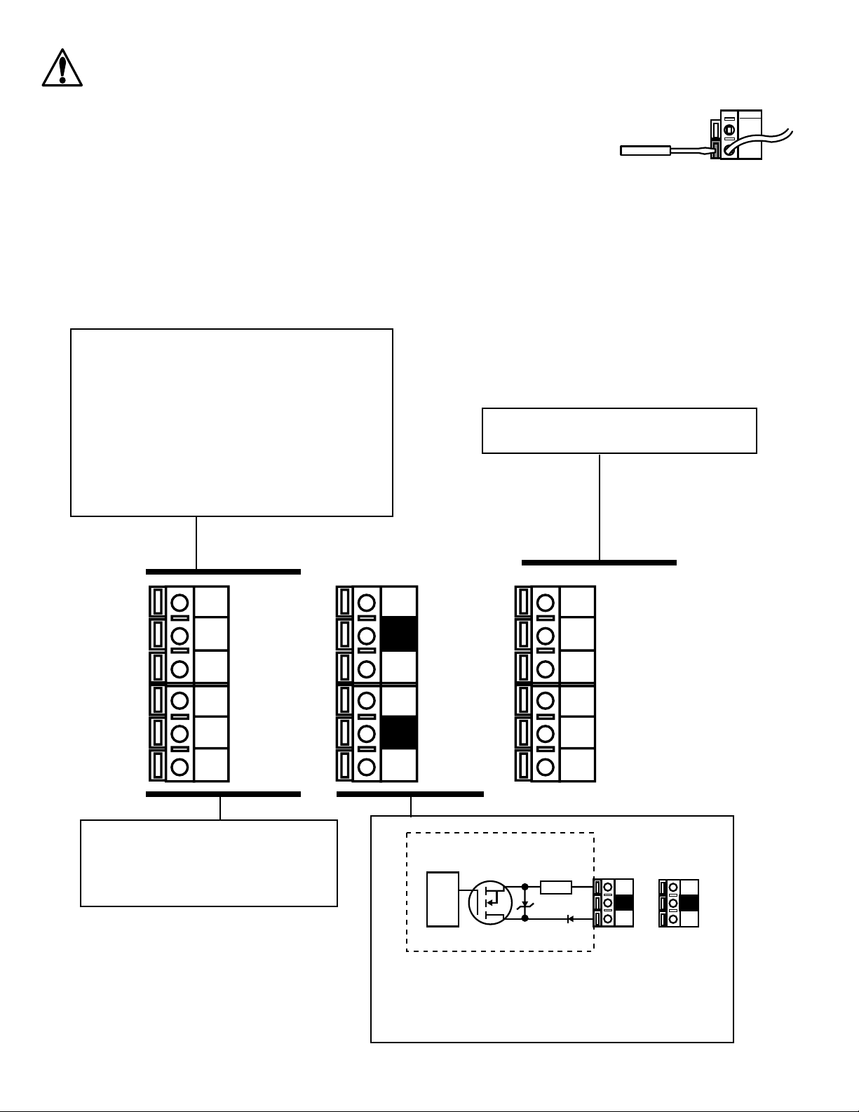
Output -
Output +
System Pwr
Loop -
System Pwr
Loop +
2
14
3
Sensr Gnd
(SHIELD)
Sensr IN
(ED)
Sensr V+
(BLACK)
7
6
5
SIDE VIEW
ield Mount &
Panel Mount Panel Mount
Installation Detail
1. Installation
ProcessPro transmitters are available in two styles: panel mount and field mount. The panel mount is supplied with the necessary
hardware to install the transmitter. This manual includes complete panel mounting instructions.
ield mounting requires one of two separate mounting kits. The 3-8052 integral kit joins the sensor and instrument together into a
single package. The 3-8050 Universal kit enables the transmitter to be installed virtually anywhere.
Detailed instructions for integral mounting or other field installation options are included with the 3-8052 Integral kit or the 3-8050
Universal kit.
1.1 Panel Installation
1. The panel mount transmitter is designed for installation using a 1/4 DIN Punch. or manual panel cutout, an adhesive
template is provided as an installation guide. Recommended clearance on all sides between instruments is 1 inch.
2. Place gasket on instrument, and install in panel.
3. Slide mounting bracket over back of instrument until quick-clips snap into latches on side of instrument.
4. To remove, secure instrument temporarily with tape from front or grip from rear of instrument. DO NOT RELEASE.
Press quick-clips outward and remove.
2. Specifications
General
• Compatibility: +G + SIGNET 2450 Pressure sensors
• System accuracy: ±1% of full scale with 2450 sensors
Enclosure:
• Rating: NEMA 4X/IP65 front
• Case: PBT
• Panel case gasket: Neoprene
• Window: Polyurethane-coated polycarbonate
• Keypad: Sealed 4-key silicone rubber
• Weight: Approx. 325g (12 oz.)
Display:
• Alphanumeric 2 x 16 LCD
• Display update rate: 1 second
• Contrast: User selected, 5 levels
Electrical
• Power: 12 to 24 VDC ±10% regulated, 60 mA max current
• Current output:
4 to 20 mA, isolated, fully adjustable and reversible
• Max loop impedance:
50Ω max. @ 12 V, 325Ω max. @ 18 V, 600Ω max. @ 24 V
• Update rate: 100 ms
• Output accuracy: ±0.03 mA
Open-collector outputs:
• Programmable for High or Low operation
• Optically isolated, 50 mA max. sink
• 30 VDC maximum pull-up voltage.
• Hysteresis: User adjustable
Environmental
• Operating temperature: -10 to 70°C (14 to 158°)
• Storage temperature: -15 to 80°C (5 to 176°)
• Relative humidity: 0 to 95%, non-condensing
• Maximum altitude: 2000 m (6562 ft)
• Insulation category: II
• Pollution degree: 2
Standards and Approvals:
• CSA, CE, UL listed
• Immunity: EN50082-2
• Emissions: EN55011
• Safety: EN61010
• Manufactured under ISO 9001 and ISO 14001
C-1/01 English