AOMWAY Nexus V2 User manual

AOMWAY 1 RC Vision System
Nexus V2
Full HD Digital Link
User Manual V 1.0
Please read through this manual before use, thank you!
www.aomway.com

AOMWAY 2 RC Vision System
1. Product Introduction
Nexus V2 is equipped with high performance decoding chip and can do
the most advanced low latency algorithm for HD video transmission. The
whole system latency is estimated to be 70ms and reach up to 7km
transmission distance, also adapt to multiple antennas for different
application purposes. This digital link device enables real time aerial
photography in full HD resolution.
5.8GHz high frequency comes with better anti-interference feature and
guarantees high image quality. Dual signal output can do auto switch, one
for 1080p micro HD camera and the other for HDin. It also has wide working
voltage range 7-26V for different power supplies. The kit perfectly supports
MAVLink protocol, can do overlapping display and set up for the OSD data
at receiver, support both HD video recording in transmitter and receiver.
2. Main Features
> Resolution:Full HD input:1080p 60fps(downward compatibility)
Camera: 1080 25fps(downward compatibility)
> Auto switch frequency or manual frequency setup
> Minimum transmission latency down to 30ms
> HD camera with HD type C port, and HD type A port
> Transmitter antenna connector is MMCX,
Receiver antenna connector is SMA-jack
> Fully support all MavLink protocol flight controller, and real time display
OSD data on screen, such as flight controller parameters, frequency, bit
stream, transmission RSSI and recording indicator etc.
> HD recording on both of transmitter and receiver side (MP4 format and
every 3min to save a recording file)
> Advance algorithm for H.264 compressed format, 20Mbps bit stream
and auto adjustment
> High frequency transmission at 5.8GHz for perfect image quality
> Use TF card for firmware upgrade (by manufacturer)
> Weight: Transmitter 60g; Receiver 108g (not include the antennas)
> Working environment: 0°C- 50°C

AOMWAY 3 RC Vision System
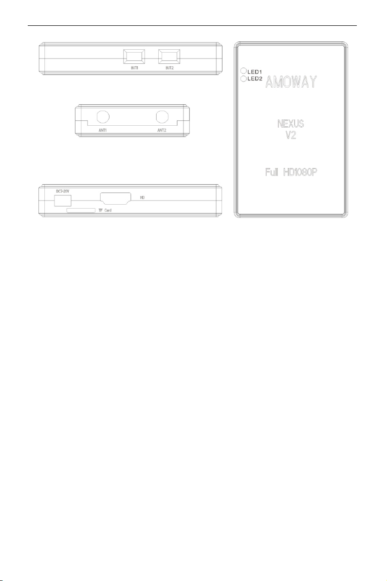
> Dimensions:Transmitter 32x62x24mm; Receiver 93x58x17mm
> Working voltage range:DC7-26V(2S-6S battery)
3. Attentions!
> Please learn how to use the product before starting operation on this
device, it is high precision electronic equipment, read this manual
thoroughly to avoid any unwanted problems or damages.
> This high frequency transmission system will generate high heat when
start to work, do NOT touch the product surface directly, especially when
there is no good condition for cooling down the device.
> Please do NOT use it under harsh environments such as extremely cold,
hot, dusty or humid environment, this can affect device performance or
causing problems.
> As a wireless transmission system, the performance and stability to be
affected by various factors, strong electromagnetic interference,
basement, high altitude, or underwater environment may result in
uncontrollable compromised performance.
> Here we reserve the right for improving the device performance, the
contents of this manual can be updated later, please follow our newly
published information on our website or online forum.
> Transmitter’s antenna connector type is MMCX, and SMA connector for
receiver side. Make sure all interfaces are connected firmly and verify all
settings to be good prior to use the equipments.
> For long term storage, please keep the device under cool or dry, sealing
preservation, and occasionally power on and check the device condition
after a certain time period.
> This device is recommended to be used by people above 14 year old.
> Before purchase and use this device please observe the local regulation
and laws, since all the related legal risks and consequences shall be borne
by the user.
4. Accessories
1x Nexus 2 HD link 1x HD data cable 2x power cord
1x camera link cable 1x flight controller cable 1x user manual

AOMWAY 4 RC Vision System
4x antennas
5. Interface diagram and button functions
> Transmitter unit:
1. UART port: for connection with controller, use RX pin on transmitter to
adopt flight controller’s TX.
2. TF Card : for HD recording and firmware upgrade on transmitter,
maximum support to 128GB.
3. LED1: Red light for indicating power/system working status.
4. LED2: Blue light for indicating data communication.
5. DC7-26V: power supply for transmitter, working voltage is recommended
to be 12v and use 3.5mm DC barrel connector(inner plus outer minus
type).
6. CAM: for camera connection, up to 1080P 25fps.
7. HD: HD type C connector,max support to 1080P 60fps or below.
8. BUT: press button (inactive, to be determined).
9. ANT1,ANT2: transmitter antenna port type as MMCX.
> Receiver unit(for ground base station):

AOMWAY 5 RC Vision System
1. BUT1: Long press 3s to display menu options (long press 3s to save
settings and quit menu).
2. BUT2: downward selection only (cycle operation).
3. ANT1 ,ANT2 :receiver’s antenna port as SMA-JACK type.
4. DC7-26V: power supply for receiver(3.5mm DC barrel connector, inner
plus outer minus type).
5. TF Card:for HD recording and firmware upgrade on receiver, maximum
support to 128GB.
6. HD: HD type A connector for output video signal.
7. LED1: yellow light for indicating power/system working status.
8. LED2: blue light for data communication.
6. Digital HD Recording Function
> Must turn off the power on device when insert or withdraw the TF card to
avoid damage to the device.
> This device can only record HD video signal, the overlapping OSD data info
cannot be recorded.
> The recording file is in MP4 format, cannot do playback function on this
device. When the TF card is inserted, the device will auto save one file in
every 3mins. (File name recorded as: AOM01,02, 03…)
> Recommended to use high speed TF card (SDC10), when device starts to
record, a REC icon will display on the screen.

AOMWAY 6 RC Vision System
> When the TF card is full or there is a card error, the recording process will
be stopped
7. Digital HD Link Operation
> Transmitter and Receiver unit already bind together (factory setting).
Manual re-binding process:
Firstly, power on the receiver and then press BUT2 key for 10s, waiting
LED1 and LED2 slow flash (one flash per second), and then release the
key, it will enter into binding status. Secondly, power on the transmitter
and press BUT key for 10s, waiting both LED indicator to do slow flash,
and then release the key, it will enter into binding status. When both LED
lights on transmitter and receiver start to quick flash, it means binding
process is completed, now you will need to restart the transmitter and
receiver for normal use.
> The blue LED light on Transmitter and Receiver is made for data
communication status. Quick flash indicates normal status; slow flash
(one flash in 3s) indicates no signal input; LED light off for malfunction
and data communication is ended.
> Once the binding process is finished, restart the device will still keep the
link.
8. Menu Selection
Long press BUT1 key for 3s to enter or quit menu, short press will change
settings. Short press BUT2 will do downward selection of menu option (cycle
operation).

AOMWAY 7 RC Vision System
> RF CH: Channel/Frequency selection (AUTO for automatic selection).
> Output Power Levels: 1mw/25mm/200mw/500mw.
> Color:change OSD info color option(red/white/yellow/black/green
/blue).
> Roll:cooperating with Radio controller(when direction is reversed).
> Pitch:cooperating with Radio controller(when direction is reversed)
> OSD: flight controller OSD data info on/off switch。
> Plane:select your aircraft type: fixed wing or FPV racing drone.
9. Flight Controller Interface
1. Current working frequency 2.Real time video signal strength
3.Bit stream(image quality)4. Receiver recording indicator
5. Flight course angle 6. Current GPS satellite numbers
7. Radio controller signal strength 8.Flight mode (flight controller)
9. Numbers indicating IAS;10. TX and RX signal connection
11. Flight attitude 12. Flight altitude
13.Transmitter current 14. Transmitter voltage status
15. Distance from start point 16. Longitude
17. Latitude

AOMWAY 8 RC Vision System
10. Firmware Upgrade
Manufacturer will upgrade the firmware version later. The upgrade zip file
can be provided to users when it is available. Firmware upgrade steps: firstly
download the zip file to the TF card, and then insert the card to the device card
slot. Power on the device, the upgrading process will start automatically.
During the process, the blue LED indicator will do quick flash. When the
upgrade process is finished, the LED indicator will stay solid on. After the
upgrading, will need to restart the device for normal use.
11. Trouble Shooting
> No image:
1. Verify if the power supply is connected well and check the LED power
indicator is solid on.
2. Verify if the HD data cable is in good condition.
3. When the OSD data info is display on screen but no image, please verify
if the video signal input to transmitter is normal.
4. Check the LED indicator for connection status. Quick flash indicates data
communication is normal, slow flash indicates no signal input; light
went off means there is malfunction and causing disconnection.
> Poor signal/close transmission distance:
1. Please check if there is other radio transmitting equipment nearby
before use this device, FPV user needs to manually select other
frequency or to avoid to use the same frequency at the same location.
2. Please avoid to use this device at railway, airport, military area, radar
station, power plant or other high magnetic field.
3. Make sure both of the antenna and receiver’s SMA connector is in
good condition and antenna is installed correctly on the device.
4. This device should be used in open area, shall avoid any signal block
caused by mountain, house, trees or other obstructions between
transmitter and receiver.
5. Make sure all antennas set in LHCP or RHCP type, no mixed use.
6. Suggest the antennas on transmitter side to be mounted as ‘V’ shape.
7. Check if the output power level has been set to maximum, or you can

AOMWAY 9 RC Vision System
try to do manual selection on other frequency.
> Signal Source:
1. This device recognizes the signal source automatically, when HD input
is available then give the priority for HD signal.
2. Most HD connection issue is caused by the data cable. Recommended
to try alternative HD signal source or change to a good quality HD cable.
3.Please choose a HD display device with lowest latency, HD cable shall
be in good condition.
4. Make sure all cable connection is done well before power on the device.
> OSD data is sent from flight controller, so if want to display the OSD info on
screen, the connection shall be done well between the transmitter and
flight controller.
www.aomway.com
Table of contents
Other AOMWAY Transmitter manuals
Popular Transmitter manuals by other brands

Linear
Linear Multi-Code 4120 installation instructions

INVISIBLE FENCE
INVISIBLE FENCE ICT 801 installation manual

Burkert
Burkert 8225 manual

Endress+Hauser
Endress+Hauser iTEMP TMT82 operating instructions

Endress+Hauser
Endress+Hauser Mycom S CLM 153 operating instructions

Campbell
Campbell SAT HDR GOES instruction manual

Dwyer Instruments
Dwyer Instruments CDX Series Installation and operating instruction manual

Omnitronic
Omnitronic TM-200A user manual

Magnavox
Magnavox MMA3336 user manual

TC FLUID CONTROL
TC FLUID CONTROL KMS-2 Installation and operating manual

Ebode
Ebode XDOM PMML user guide

Security Brands
Security Brands 14-R300 instructions