iGenix IG9909 User manual
3-in-1 Portable Air Conditioner White
Please read these instructions carefully before use and retain for future reference
Before switching on your appliance,
always check for any damage which may have been caused in transit
IG9909
USER MANUAL

2
CONTENTS
Safety Instructions...................................................................3-4
Specication .................................................................................5
Appliance Overview...................................................................6
Installation.................................................................................7-9
Operating Instructions...................................................... 10-14
Water Drainage.................................................................. 15-16
Cleaning and Maintenance ..................................................... 17
Trouble Shooting Guide.......................................................... 18
Error Codes .............................................................................. 19
Fuse Replacement.................................................................... 20
Disposal Information............................................................... 20
Igenix Warranty Information ........................................... 22-23

3
Carefully read the instructions before operating the unit. Please
retain this manual for future reference.
Important: This product is intended for domestic and light ofce
use ONLY and not for commercial, industrial or outdoor use.
When using electrical appliances, basic safety precautions should
always be followed:
1. All electrical repairs must be carried out by a qualied
electrician. Inadequate repairs may result in a major source of
danger for the user and invalidate the warranty.
2. Do not operate the unit if the plug or cord is damaged, after it
malfunctions or has been dropped or damaged in any way, it
must be repaired by a qualied electrician.
3. Make sure the unit is connected to an earthed power supply of
the correct rating. Please refer to the rating label located at the
side of the unit.
4. Leave the unit to stand for 12 hours before connecting to the
mains electricity supply after transport or when it has been
tilted (e.g. cleaning), to allow the coolant gases time to settle.
5. Use of an extension cord is not recommended with this product.
6. This unit should only be used by adults.
7. Keep the unit and its cord out of reach of children.
8. Children shall not play with the appliance.
9. Cleaning and user maintenance shall not be made by children.
10. The unit should not be used by persons with reduced physical,
sensory or mental capabilities.
11. It is not recommended to place this appliance in cupboards,
closets, boats, caravans or similar locations.
12. Do not use the unit in a wet room, such as a bathroom or
laundry room or in areas where the unit is likely to get splashed.
13. An opening in a window or wall is required to accommodate the
exhaust hose to expel the hot air.
14. Always place unit on a dry and stable surface.
SAFETY INSTRUCTIONS

4
15. Do not cover or obstruct the unit’s inlet and outlet grilles.
16. Do not insert ngers, pencils or any other objects into the
opens of the unit.
17. Avoid restarting the appliance unless 3 minutes have passed
since being turned off.This prevents damage to the compressor.
18. Do not let chemical substances come into contact with the
appliance.
19. It is not recommended to use ammable substances or vapours
such as alcohol, insecticides, petrol, etc. whist the unit is in use.
20. Do not clean the unit by spraying it or immersing in water.
21. Do not unplug the unit while it is working, this could damage the
electronic circuits.Always use the control panel to start and stop
the unit.
22. Always turn the unit off when not in use by removing the plug
from the wall socket; ensuring to pull the plug top and not
the cord.Always turn off the unit before cleaning, carrying out
maintenance or moving location.
23. Do not pull or place the electrical cable near a source of heat:
always unroll it completely to avoid dangerous overheating.
24. The lter must be used with the product at all times, when
removing it for clearing always turn the unit off and unplug from
the mains wall socket.

5
SPECIFICATION
Model IG9909
Cooling Capacity (Btu) / (W) 9000Btu / 2600W
Heating Capacity (Btu) / (W) n/a
Dehumidication at 30°C/80%RH (L/day) 31.2
Cooling Input Power (W) 1000
Heating Input Power (W) n/a
Air FlowVolume (m³/h) 300
Power Supply (Hz) 50
Compressor Rotary
Refrigerant R290
Fan Speeds High / Low
Timer Ye s
Operating Temperature (°C) 18 - 35
Energy Rated Class A
Room Size (m²) Up to 20m2
Net Weight (kg) 26
Product Dimensions (H x W x D) (mm) 695 x 340 x 340
Unit must be vented outside when in Air Cooling and Heating Modes.
For the purpose of EU regulation EN12102, this is a local air conditioner and produces less than
65dB(A) sound energy
6
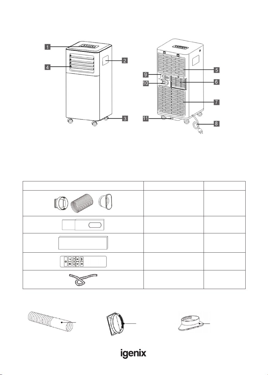
APPLIANCE OVERVIEW
Front Back
Accessories
Parts Parts Name Quantity
Exhaust hose connector
Exhaust hose
Exhaust hose adapter
1 set
Window slider kit 1 set
Window slider without
hole 1 set
Remote control 1 set
Drainage hose 1 set
1. Control panel
2. Handle (both sides)
3. Castors
4. Louvres
5. Intake grille
6. Air outlet grille
7. Intake grille
8. Power cable
9. Plug xer
10. Drainage point
11. Drainage point
Exhaust Assembly
Exhaust
hose
Exhaust hose
connector
Exhaust hose
adapter
7
INSTALLATION
Warning: Leave the unit to stand for 12 hours before connecting to the mains electricity supply
after transport or when it has been tilted (e.g. cleaning), to allow the coolant gases time to settle.
Unpacking
• Open the box and remove all of the packaging and the exhaust assembly
• Grip the unit by the carry handles located on either side and carefully lift until it slides out of
the foam base
• Install the exhaust hose assembly onto the unit before switching on
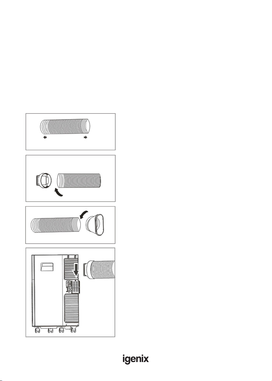
Installing Exhaust Hose
Extend the exhaust hose by pulling out the two ends of
the hose.
Screw the exhaust hose into the exhaust hose
connector, turning anti-clockwise.
Screw the other end of the exhaust hose onto the
exhaust hose adaptor.
Slide the exhaust hose assembly into the exhaust duct
located on the back of the unit, ensuring the connector
has clicked into place.
Fig.1
Fig.2
Fig.3
Fig.4
Extend the side of hose
Insert

8
Positioning the Appliance
This unit can easily be moved from one room to another on the rolling castor wheels, please note
that whilst moving the unit, it should be kept in an upright position.
• The exhaust heat must be expelled through a window, door
or vented through a wall; whilst in air cooling or heating
mode. For best results it is recommended to vent through
a wall duct.
• Ensure the unit is positioned on a at and even surface,
at least 45cm away from wall, curtains, draperies, or heat
sources to ensure adequate air circulation.
• The exhaust hose can be extended from 30cm to 150cm,
but it is recommended to use as short as possible as this
will minimise the escape of any expelled air and offer better
results.
• The exhaust air must ow freely. Avoid kinks and bends in
the hose more than 30 degrees as any blockages can lead to
the unit overheating.
Warning: Do not use the unit in a wet room, such as a bathroom or laundry room or in areas
where the unit is likely to get splashed.
Important: The length of the exhaust hose has been designed according to the specication of
the appliance. Do not extend the exhaust hose with any other product as this could lead to the
unit malfunctioning
Using the Window Slider
Fig.5 Fig.6
VerticalVertical
WindowWindow
HorizontalHorizontal
WindowWindow
Window sliderWindow slider Window sliderWindow slider
The window slider kit has been designed to t most standard vertical and horizontal window
applications, however, it may be necessary for you to modify some aspects of the installation
procedures for certain types of windows.The window slider kit can be fastened with screws.
Cut on opposite
side of hole
Note: If the window opening is less than the minimum length
of the window slider kit, cut the end without the hold in it short
enough to t in the window opening. Never cut out the hole in
window slider kit.

9
Window Slider Kit Installation
A. Panel
B. Panel with one hole
C . Screw to lock window kit in place
Assembly:
• Slide panel B into Panel A and size to window width. Ensure that the window kit assembly is free
from gaps from gaps and/or air pockets when taking measurements.
• Lock the screw into the holes that correspond
• With the width that your window requires to ensure that there are no gaps or air pockets in
the window kit assembly after installation.
10
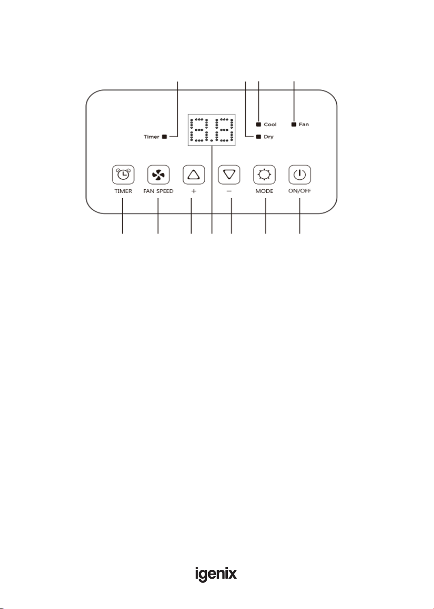
OPERATING INSTRUCTIONS
When box is lit up, this shows:
A. Timer enabled
B. Low speed fan selected
C . High speed fan selected
D. Dehumidify mode selected
E. Cooling mode selected
F. Fan mode selected
1. Timer button
2. Fan button
3. Increase temperature button
4. Display screen
5. Decrease temperature button
6. Mode button
7. ON/OFF button
EEBBAACC
11332244556677
Control Panel
11
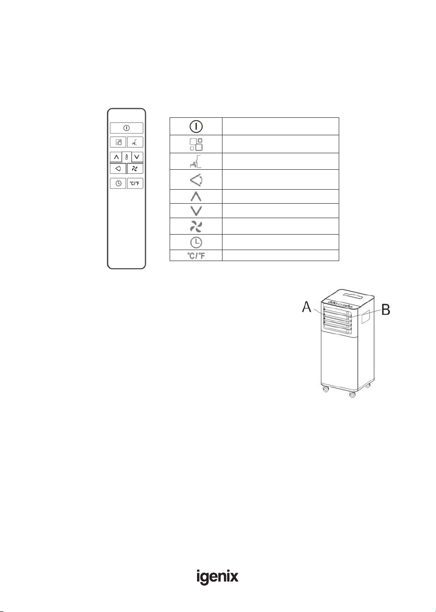
Remote Control
On/Off button
Mode button
Sleep button
Swing button
(not available on this model)
Increase temp. button
Decrease temp. button
Fan speed button
Timer button
Unit Switch button
NOTE: This serial model has no auto swing
function. Please adjust the louvres manually
to the required position.
• Point the remote control at the receiver on the appliance.
• The remote control must be no more than 7 meters away from
the appliance (without obstacles between the remote control and
the receiver).
• The remote control must be handled with extreme care. Do not
drop it or expose it to direct sunlight or sources of heat. If the
remote control does not work, please try to take out the battery,
and put it back.
Inserting or Replacing the Batteries
• Remove the cover on the rear of the remote control
• Insert two "AAA" 1.5V batteries in the correct position (see instructions inside the battery
compartment
NOTE
• If the remote control unit is replaced or disposed of, the batteries must be removed and
discarded in accordance with current legislation as they are harmful to the environment.
• Do not mix old and new batteries. Do not mix alkaline, standard (carbon-zinc) or rechargeable
(nickel-cadmium) batteries.
• Do not dispose of batteries in re. Batteries may explode or leak.
• If the remote control is not be used for a certain length of time, remove the batteries
A: Horizontal louvres
B: Vertical louvres
NOTE: Certain modes and functions can only be controlled via
the remote control, therefore always ensure that the remote
control is keep in a safe place to avoid accidentally losing or
misplacing it.
12
Modes
The IG9909 features 3 main functions: Cooling, Fan and Dehumidier.
Important: The compressor will start approximately 3 minutes after the unit is turned on (this
will help prolong the life of the compressor).After switching the unit off, please wait at least 3
minutes before turning the unit back on.
Cool Mode
Ideal for hot muggy weather when you need to cool and dehumidify the room.
To set this mode correctly:
• Press the “ ” button a number of times until the “Cool” symbol light appears.
• Select the target temperature (18°C-32°C) (64°F-90°F) by pressing the “ ” or “ ” button until
the corresponding value is displayed.
• Select the required fan speed by pressing the “ ” button. Different fan speeds are intended for:
High - To achieve the desired temperature as fast as possible
Low - Running at low noise and maintaining the temperature once reached
• The most suitable temperature for the room during the summer varies from 24°C to 27°C
(75°F to 81°F). You are recommended, however, not to set a temperature much below the
outdoor temperature.
• The fan speed difference is more noticeable when the appliance is under FAN mode but may
not be noticeable under COOL mode.
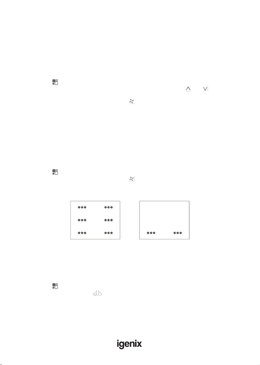
Fan Mode
When using the appliance in this mode, the air hose does not need to be attached.
• Press the “ ” button a number of times until the “Fan” symbol light appears.
• Select the required fan speed by pressing the “ ” button.
• High and low speeds will appear on the display screen as below:
Dry Mode
Ideal to reduce room humidity (spring and autumn, damp rooms, rainy periods, etc).
In dry mode, the appliance should be prepared in the same way as for cool mode, with the air
exhaust hose attached to enable the moisture to be discharged outside.
To set this mode correctly:
• Press the “ ” button a number of times until the “Dry” symbol light appears.
• The display screen will show “ ”
• In this mode, fan speed is selected automatically by the appliance.
High Low

13
Sleep Mode
NOTE: This mode is only available when using the remote control and cannot
be controlled via the main control panel
This function is intended for using the unit at night as it gradually reduces operation of the
appliance.
To set this function correctly:
• Select the cool or heat mode as described above.
• Press the “ ” button.
The appliance will operate in the previously selected mode, but with reduced brightness and noise
level.
The SLEEP function maintains the room at optimum temperature without excessive uctuations
in either temperature or humidity with silent operation. Fan speed is always at Low, while room
temperature and humidity vary gradually to ensure the most comfortable.
When in COOL mode, the selected temperature will increase by 1°C (1°F) per hour in a 2 hour
period.This new temperature will be maintained for the next 6 hours.Then the appliance turn it off.
The SLEEP function can be cancelled at any time during operation by pressing the “Sleep”,“Mode”
or “fan speed” button.
In FAN or DRY mode, SLEEP function cannot be set.
Setting the Timer
This timer can be used to delay the appliance start up or shut down.This avoids wasting
electricity by optimising operating periods.
Programming start up:
• Turn on the appliance and choose the desired mode (for example cooling, 24°C and high fan
speed)
• Turn off the appliance.
• Press the “ ” button and the screen will display 1-24 hours.
• Press several times until the corresponding time is displayed.
• Wait about 5 seconds, then timer will be active, signied by the ‘Timer’ symbol on the display
screen.
• Press the “ ” button to cancel this timer.The ”Timer” symbol will disappear from the display
screen.
Programming shut down:
• While the appliance is running, please press the button, the screen will display 1-24 hours.
• Press several times until the corresponding time is displayed.Wait about 5 seconds, the timer
Fig.7
Fig.8
will be active, then “Timer” symbol is displayed on screen.
• Press again the “ ” button, the timer will be cancelled, and the ”Timer”
symbol will disappear from the display screen.
Switch the Unit of Temperature
When the appliance is running, press the button, then you can change
the unit of temperature between degrees Celsius and degrees Fahrenheit.
For examples:
Before changing the unit, in cool mode, the display screen will look like Fig.7.
After changing the unit as above, in cool mode, the screen display like Fig.8.
14
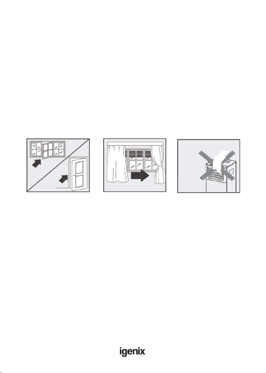
Tips For Correct Use
To get the best from your appliance, follow the below recommendations:
• Close the windows (that aren’t being used for venting) and doors in the room to be air
conditioned (Fig.9).When installing the appliance semi-permanently, you should leave a door
slightly open (as little as 1 cm) to guarantee
• correct ventilation
• Protect the room from direct exposure to the sun by partially closing curtains and/or blinds to
make the appliance much more economical to run (Fig.10)
• Never rest objects of any kind on the appliance
• Do not block the air inlet or outlet of the appliance
• Reduced air ow will result in poor performance and could damage the unit (Fig.11)
• Make sure there are no heat sources in the room
• Never use the appliance in very damp rooms (laundries for example)
• Never use the appliance outdoors
• Make sure the appliance is standing on a level surface. If necessary, place the castor locks under
the front wheels
Fig.9 Fig.10 Fig.11
15
WATER DRAINAGE
With daily use, it is recommended to empty the unit approximately once a week.
The unit can be drained manually or continuously, as explained below:
Manual Draining (Fig.12)
• Unplug the unit from power source.
• Place a suitable container (not supplied with unit)
under the lower drain plug. See diagram.
• Remove the lower drain plug.
• Water will drain out and collect in the pan.
• After the water is drained, replace the lower drain
plug rmly.
• Turn on the unit.
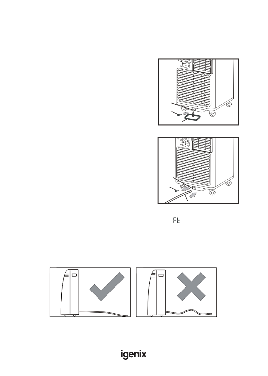
Continuous Draining (Fig.13)
• Unplug the unit from the power source.
• Remove the drain plug.While doing this, some
residual water may spill so have a suitable pan or
container ready to collect the water (not supplied
with unit.
• Connect the drain hose. See diagram.
• The water can be continuously drained through the
hose into a oor drain or bucket.
• Turn on the unit.
If the unit has not been emptied frequently enough and there is excess water condensation inside
the unit, the appliance will stop running and shows the error code “ ” (FULL TANK).
This indicates that the water condensation needs to be drained using one of the above procedures.
NOTE
Ensure that the drain hose is not higher than that of the drain outlet, or the water tank may not
drain fully. (Fig.14 & Fig.15)
Fig.12
DrainDrain
outletoutlet
DrainDrain
capcap
PanPan
Fig.13
DrainDrain
outletoutlet
DrainDrain
capcap
Drain hoseDrain hose
Fig.14 Fig.15

16
Middle Drainage
When unit running in Dry mode, you can choose to drain the system from the middle drainage
outlet as below:
1. Unplug the unit from the power source.
2. Remove the drain plug (Fig.16).While doing this, some residual water may spill so ensure you
have a pan ready to collect the water (not supplied with unit).
3. Connect the drain hose (Fig.17)
4. The water can be continuously drained through the hose into a oor drain or bucket.
5. Turn on the unit.
NOTE: Ensure that the drain hose is not higher than the middle drain outlet, or the water tank
may not drain fully. (Fig.18 and Fig.19)
Fig.16 Fig.17
Drain capDrain cap
Drainage hoseDrainage hose
Fig.18 Fig.19
17
CLEANING & MAINTENANCE
Cleaning the Cabinet
Before any cleaning or maintenance, turn the appliance off by pressing the “ ” button on the
control panel or remote control.Wait for a few minutes then unplug from the mains socket.
You should clean the outer cabinet of the appliance with a slightly damp cloth, then dry with a dry
cloth. Do not use water to wash appliance.
• Never wash the appliance with water. It could be dangerous.
• Never use petrol, alcohol or solvents to clean the appliance.
• Never spray antibacterial liquids or similar.
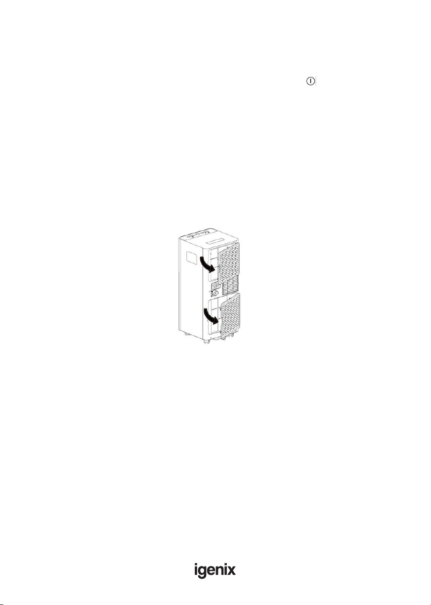
Cleaning the Air Filters
To keep your appliance working efciently, it is recommended that you clean the lter every week
of operation.
As per Fig.20, open the grid of appliance, then take out evaporator from the back of grid.
Avoid contact with the metal parts of the appliance when removing or re-installing the lter to
reduce the risk of personal injury.
Use a vacuum cleaner to remove dust accumulations from the lter. If it is very dirty, immerse in
warm water and rinse several times. The water should never be hotter than 40°C (104°F). After
washing, leave the lter to dry fully then re-attach the intake grille to the appliance.
Start of Season Operations
Make sure the power cable and plug are undamaged and properly earthed.
Follow the installation instructions precisely.
End of Season Operations
To empty the internal circuit completely of water, remove the cap. Run off all water left into a basin.
When all the water has been drained, put the cap back in place.
Clean the lter and dry thoroughly before putting back.
Strictest Operation Environment
Cooling mode: 18°C-35°C (64°F-95°F), 30%RH~90%RH
Fig.20

18
TROUBLE SHOOTING GUIDE
If you experience difculties with the appliance, please check the suggestions below before
contacting customer services:
Problem Solution
The unit will not switch on
• Check Trip Switch / Fuse
• Wait for 3 minutes and start again, protective device
may be preventing unit from working
• Check if the plug is connected to mains socket
correctly
• Check batteries in the remote control
Runs for a short while then switches
off
• If the set temperature is close to room temperature,
the unit will automatically switch off, you can lower
the set temperature to restart • Check if there are
bends or obstacles in the air exhaust hose, if so
remove obstacle
• Check if Timer function has been activated
Runs without cooling in Air
Conditioning mode
• Ensure the air exhaust hose is vented correctly out of
a window or through a wall duct
• Close any open doors or windows
• Remove any other appliance creating heat in the same
room
• Check if the air lter is dirty – if so, clean
• Check if air outlets or inlets are blocked
• The set temperature is too high
• Check the room is the correct size for the
recommended specication of the unit (see
specication table above)
During operation, the unit is creating
an unpleasant smell in the room • Clean the air lter as described above
Water is leaking from unit
• Drain the water tank – refer to Water Drainage
section
• Ensure rubber caps are securely tted to drainage
points
• Ensure unit is located on a at and even surface

19
ERROR CODES
Error Code Solution
PROBE FAILURE
(sensor damaged)
• If this is displayed, contact your local authorised
service centre.
FULL TANK
(safety tank full)
• Empty the internal safety tank, following the
instructions in the “End of Season Operations”
paragraph.
20
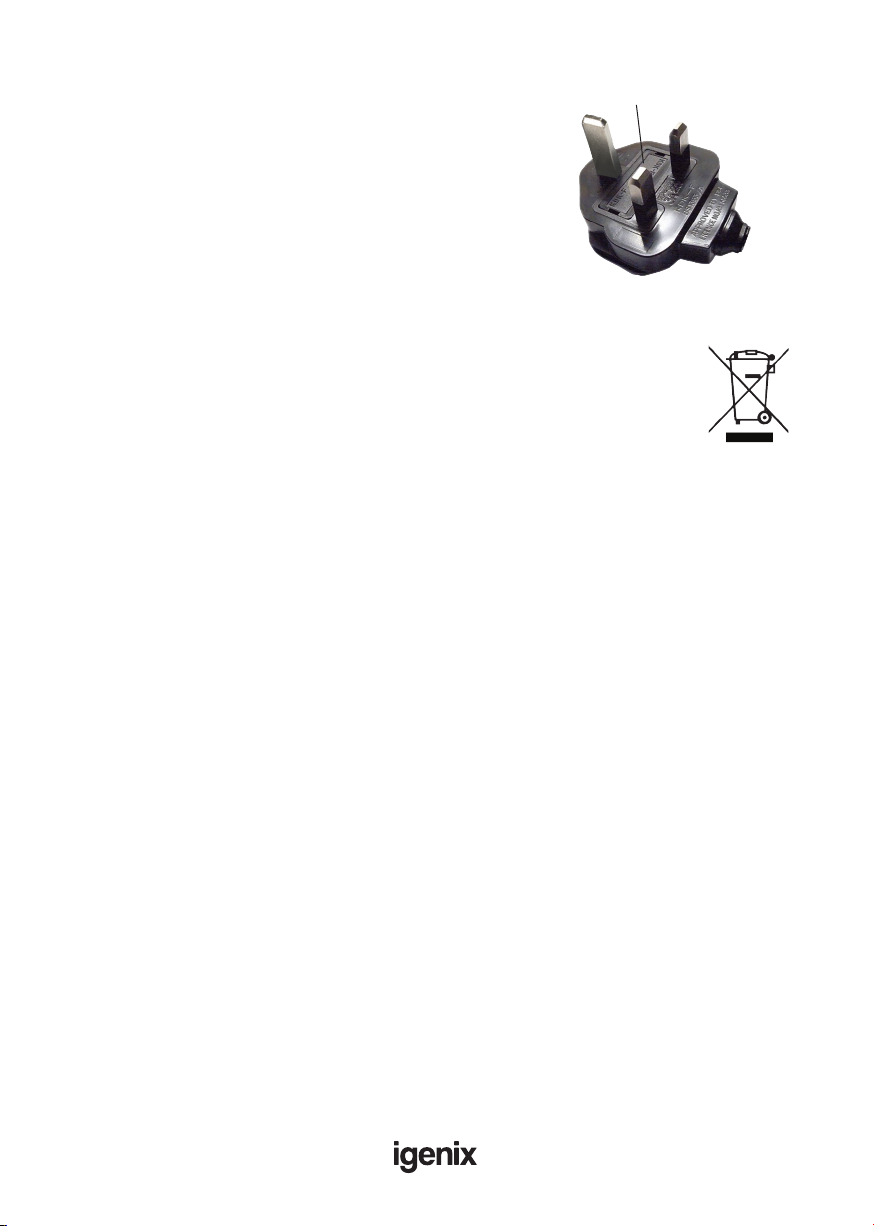
DISPOSAL INFORMATION
The European Directive 2012/19/EU on Waste Electrical and
Electronic Equipment (WEEE), requires that old household
electrical appliances must not be disposed of in normal unsorted
municipal waste.
Old appliances must be collected separately in order to optimise
the recovery and recycling of the materials they contain and reduce the impact
on human health and the environment.
The crossed out “wheeled bin” symbol on the product reminds you of your
obligation, that when you dispose of the appliance it must be separately collected.
Consumers should contact their local authority or retailer for information
concerning the correct disposal of their old appliance.
MAINS PLUG FUSE REPLACEMENT Fuse Cover
Fuse Replacement (Class I)
This appliance must be eathed. Remove the fuse cover with a small
at head screw driver. Take out the fuse and replace with a new fuse
of the same Amp. Replace the fuse cover and push back into place.
Table of contents
Other iGenix Air Conditioner manuals

iGenix
iGenix IG9703 User manual

iGenix
iGenix IG9704 User manual

iGenix
iGenix IG9909WIFI User manual

iGenix
iGenix IG9703 User manual

iGenix
iGenix IGFD7010WIFI User manual

iGenix
iGenix IG9907 User manual

iGenix
iGenix IG9902 User manual

iGenix
iGenix IG9900 User manual

iGenix
iGenix IG9919 User manual

iGenix
iGenix IG9901WIFI User manual


Popular Air Conditioner manuals by other brands


Emerson
Emerson CORESENSE Application Engineering Bulletin

McQuay
McQuay Suite II Installation & maintenance data

Unical
Unical CMCS 12HI user manual

Toshiba
Toshiba RAS-18N3KV-E Service manual

Bryant
Bryant SINGLEPACKAGED AIR CONDITIONER 564A User's information manual

Koldfront
Koldfront WAC8001W owner's manual