iglu Inuit 6I User manual

5
INSTALLATION MANUAL
AIR-TO-WATER HEAT PUMP IGLU® INUIT

TABLE OF CONTENT
INTRODUCTION ..........................................................................................................................................................................................................................5
PURPOSE.....................................................................................................................................................................................................................................5
LIABILITY.....................................................................................................................................................................................................................................5
WARRANTY.................................................................................................................................................................................................................................5
PRODUCT PACKAGING AND TRANSPORTATION................................................................................................................................................................5
SAFETY PRECAUTION...........................................................................................................................................................................................................6
WARNING.................................................................................................................................................................................................................................6
PRODUCT SPECIFICATION.......................................................................................................................................................................................................8
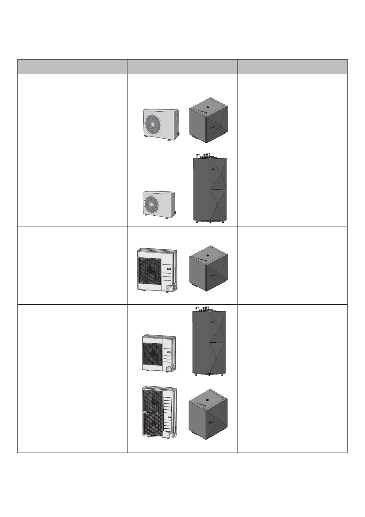
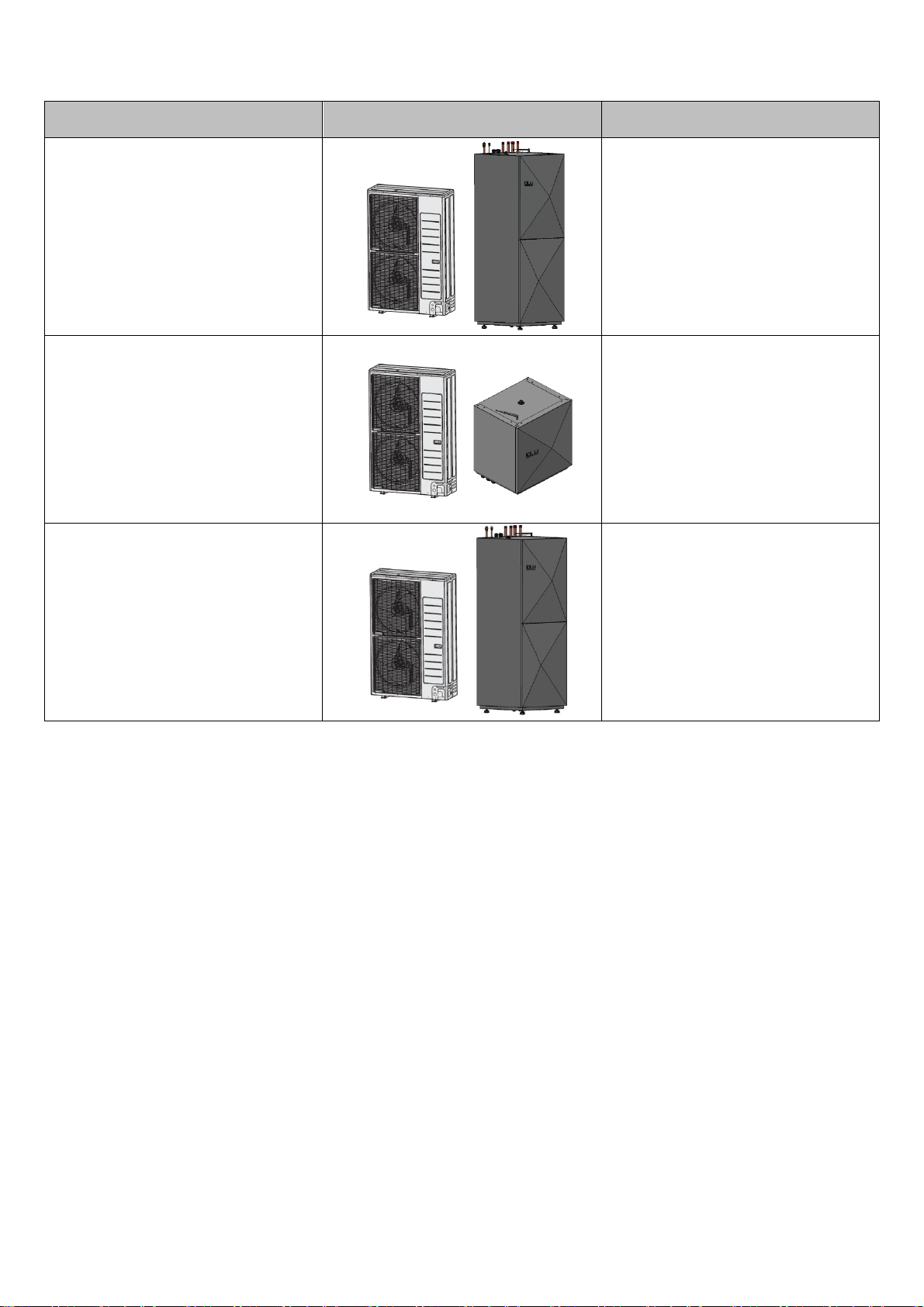
PRODUCT LINE-UP.................................................................................................................................................................................................................8
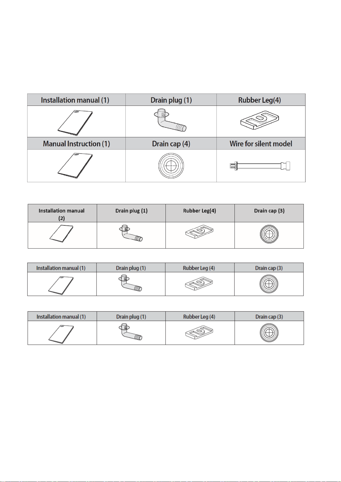
ACCESSORIES......................................................................................................................................................................................................................10
UNIT SPECIFICATION (without water tank) ..........................................................................................................................................................................11
UNIT SPECIFICATION (with water tank)................................................................................................................................................................................12
CAPACITY TABLE.................................................................................................................................................................................................................13
MAIN COMPONENTS................................................................................................................................................................................................................15
DIMENSIONS..........................................................................................................................................................................................................................15
INSTALING THE UNIT...............................................................................................................................................................................................................20
HEATING SYSTEM FILLING.................................................................................................................................................................................................22
HEATING SYSTEM FILTER AND VALVES .........................................................................................................................................................................22
INTERNAL CIRCUIT CIRCULATION PUMP........................................................................................................................................................................22
THE HEATING SYSTEM RISING AND FILLING .................................................................................................................................................................22
THERMAL INSULATION .......................................................................................................................................................................................................22
CAUTION................................................................................................................................................................................................................................23
PREPARATION OF FIRE EXTINGUISHER..........................................................................................................................................................................24
IGNITION SOURCES FREE ..................................................................................................................................................................................................24
AREA VENTILATION.............................................................................................................................................................................................................24
LEAKAGE DETECTION METHODS.....................................................................................................................................................................................25
LABELLING............................................................................................................................................................................................................................25
RECOVERY ............................................................................................................................................................................................................................25
INSTALING THE UNIT...........................................................................................................................................................................................................25
MOVING THE OUTDOOR UNIT BY WIRE ROPE................................................................................................................................................................26
SPACE REQUIREMENTS FOR OUTDOOR UNIT...............................................................................................................................................................27
WHEN INSTALLING ONE OUTDOOR UNIT....................................................................................................................................................................27
WHEN INSTALLING MORE THAN ONE OUTDOOR UNIT.............................................................................................................................................28
SPACE REQUIREMENTS FOR INDOOR UNIT...................................................................................................................................................................29
WHEN INSTALLING ONE INDOOR UNIT ........................................................................................................................................................................29
WITH WATER TANK..........................................................................................................................................................................................................29
WHEN INSTALLING MORE THAN ONE INDOOR UNIT.................................................................................................................................................30
WITH WATER TANK..........................................................................................................................................................................................................30
WHEN INSTALLING ONE INDOOR UNIT ........................................................................................................................................................................31
WITHOUT WATER TANK..................................................................................................................................................................................................31
WHEN INSTALLING ONE INDOOR UNIT ........................................................................................................................................................................32
WITHOUT WATER TANK..................................................................................................................................................................................................32
OUTDOOR UNIT INSTALLATION............................................................................................................................................................................................33
OUTDOOR UNIT SUPPORT .................................................................................................................................................................................................34
DRAIN WORK.........................................................................................................................................................................................................................35
HEAVY SNOWFALL AREA...................................................................................................................................................................................................37
SELECTING A LOCATION IN COLD CLIMATES................................................................................................................................................................38

OUTLET AND INLET SCHEME OF INDOOR UNIT.................................................................................................................................................................39
ELECTRICAL SCHEMES..........................................................................................................................................................................................................41
CONNECTING THE CABLES ...............................................................................................................................................................................................44
SPECIFICATION OF CONNECTION CABLES (COMMON IN USE)..................................................................................................................................44
INSTALLING THE EARTH WIRE..........................................................................................................................................................................................47
EARTHING THE POWER CABLE ........................................................................................................................................................................................47
HOW TO CONNECT YOUR EXTENDED POWER CABLES ..............................................................................................................................................48
REFRIGERANT PIPING WORK................................................................................................................................................................................................50
ALLOWABLE LENGTH OF THE REFRIGERANT PIPE AND THE INSTALLATION EXAMPLES ..................................................................................50
INSTALING INDOOR UNIT .......................................................................................................................................................................................................51
TYPICAL APPLICATION EXAMPLES .....................................................................................................................................................................................51
MAIN COMPONENTS................................................................................................................................................................................................................52
SELECTING THE REFRIGERANT PIPE..................................................................................................................................................................................54
CUTTING OR FLARING THE PIPES........................................................................................................................................................................................54
REFRIGERANT PIPING WORK................................................................................................................................................................................................56
SELECTING THE INSULATOR OF THE REFRIGERANT PIPE.........................................................................................................................................56
INSULATING THE REFRIGERANT PIPE.............................................................................................................................................................................57
BRAZING THE PIPE ..............................................................................................................................................................................................................57
REPLACEMENT OF NITROGEN GAS.....................................................................................................................................................................................57
PERFORMING THE REFRIGERANT GAS LEAK TEST .....................................................................................................................................................58
VACUUM DRYING .................................................................................................................................................................................................................59
SELECTING AN ADDITIONAL REFRIGERANT CHARGE ....................................................................................................................................................60
CHARGING REFRIGERANT.................................................................................................................................................................................................60
ADDING REFRIGERANT.......................................................................................................................................................................................................62
TO CLOSE THE VALVE STEM.............................................................................................................................................................................................63
TO OPEN THE VALVE STEM ...............................................................................................................................................................................................63
CHECKING CORRECT GROUNDING......................................................................................................................................................................................64
SETTING THE OPTION SWITCH AND FUNCTION OF THE KEYS ......................................................................................................................................65
SETTING THE OPTION .........................................................................................................................................................................................................66
PUMP DOWN PROCEDURE.....................................................................................................................................................................................................68
OBJECTIVE OF PUMPING DOWN.......................................................................................................................................................................................68
CAUTIONS WHEN PERFORMING PUMP DOWN...............................................................................................................................................................68
COLLECTING REFRIGERANT IN REFRIGERANT VESSEL BEFORE PUMP DOWN OPERATION.............................................................................69
COMPLETING THE INSTALLATION .......................................................................................................................................................................................70
FINAL CHECKS AND TRIAL OPERATION .............................................................................................................................................................................70
INSPECTION BEFORE TEST OPERATION ........................................................................................................................................................................70
TEST OPERATION ................................................................................................................................................................................................................70
TROUBLESHOOTING...............................................................................................................................................................................................................71
ERROR CODES .....................................................................................................................................................................................................................71

Correct Disposal of This Product
(Waste Electrical & Electronic Equipment)
(Applicable in countries with separate collection systems)
This marking on the product, accessories or literature indicates that the product and its electronic accessories
(e.g., charger, headset, USB cable) should not be disposed of with other household waste at the end of their
working life. To prevent harm to the environment or human health from uncontrolled waste disposal, please
separate these itemsfrom other types of waste and recycle them responsibly to promote the sustainable reuse of
material resources.
Household users should contact either the retailer where they purchased this product, or their local government
office, for details of where and how they can take these items for environmentally safe recycling.
Business users should contact their supplier and check the terms and conditions of the purchase contract. This
product and its electronic accessories should not be mixed with other commercial wastes for disposal.

5
INTRODUCTION
This installation manual provides information on the installation of the IGLU heat pump. It is an integral part of the product
and must be easily accessible to the installer. The manual must be available throughout the life of the device. In the event
of a change in the owners of the device, the manual must be passed on to the new owners or users.
Read the instructions before installing the heat pump. Follow all instructions as specified by the manufacturer.
If you have any questions, please contact the company that performs the installation of heat pumps or your local
manufacturer’s representative.
This installation manual was written for several types of devices; you must always follow the parameters applicable to the
respective type of equipment.
PURPOSE
The manual is intended only for persons who install the devices. Treat all constituents responsibly. The heat pump may
only be used for its intended purpose, which means:
• heating.
• domestic hot water preparation.
• cooling.
The device can only be operated according to its technical parameters.
LIABILITY
The manufacturer shall not be liable for damage caused by improper use or installation of the heat pump. The
manufacturer’s liability shall also not apply:
• if work has been performed that differs from the specifications in these operating instructions.
• if work has been carried out on the equipment which is not described in this manual or which has not been approved in
writing by the manufacturer.
• if the equipment or its components have been modified, altered, or removed without the written consent of the
manufacturer.
WARRANTY
The product has a 24-month warranty upon submission of the purchase documents.
The product warranty can be extended up to 60 months with annual heat pump maintenance.
Warranty and post-warranty provisions are available in the purchase documents.
PRODUCT PACKAGING AND TRANSPORTATION
After purchasing a heat pump:
• Inspect the delivered product for external damage during delivery.
• In the event of delivery defects, submit a claim to the company that sold the device immediately.
The heat pump may only be transported and stored in an upright position. The device can only be temporarily tilted, not
laid down. The device can be stored at a temperature no lower than 10 °C.

6
SAFETY PRECAUTION
Carefully follow the precautions listed below because they are essential to guarantee the safety of Iglu Tech product.
Always disconnect the power supply of the Air-Water Heat Pump before servicing it or accessing components inside the
unit.
WARNING
•Verify that installation and testing operations shall be performed by qualified personnel.
•To prevent severe damage tothe system and injuriesto users, precautionsand other notices shall
be observed.
Carefully read the content of this manual before installing the air-to-water heat pump and store the manual in
a safe place to be able to use it as a reference after installation.
•For maximum safety, installers should always carefully read the following warnings.
•Store the operation and installation manual in a safelocation and remember to hand it over to the newowner
if the Air to Water Heat pump is sold or transferred.
•Store the user and installation manual in a safe location and remember to hand it over to the new owner if
the air to water heat pump is sold or transferred.
•This manual explains how to install an Air-Water Heat Pump. The use of other types of units with different
control systems may damage the units and invalidate the warranty. The manufacturer shall not be responsible
for damages arising from the use of non-compliant units.
•The manufacturer shall not be responsible for damage originating from unauthorized changes or the
improper connection of electric and hydraulic lines. Failure to comply with these instructions or to comply with
the requirements outlined in the “Operating limits” table, included in the manual, shall immediately invalidate
the warranty.
•Failure to comply with these instructions or to comply with the requirement on the Operating Range (Heat: -
25~35 °C/ Cool: 10~46 °C) outlined in the Product Specification hall immediately invalidate the warranty.
•Do not use the units if you see some damage on the units and recognize something bad such as loud noise,
or smell of burning.
•To prevent electric shocks, fires, or injuries, always stop the unit, and disable the protection switch and
contact.
•IGLU TECH’s technical support if the unit produces smoke if the power cable is hot or damaged or if the unit
is very noisy.
•Always rememberto inspect the unit, electric connections, refrigerant tubes, and protections regularly. These
operations shall be performed by qualified personnel only.
•The unit contains moving parts and electrical parts, which should always be kept out of the reach of children.
•Do not attempt to repair, move, alter, or reinstall the unit by unauthorized personnel, these operations may
cause product damage, electric shocks, and fires.
•Do not place containers with liquids or other objects on the unit. All the materials used for the
manufacture and packaging of the air to water heat pump are recyclable.
•The packing material and exhaust batteries of the remote controller(optional) must be disposed of by local
regulations.
The air-to-water heat pump contains a refrigerant that must be disposed of as special waste. At the end of its
life cycle, the heat pump must be disposed of in authorized centers or returned to the retailer so that it can be
disposed of correctly and safely.
•Wear protective gloves to unpack, move, install, and service the unit to avoid your hands being injured by
the edge of the parts.
•Do not touch the internal parts (water pipes, refrigerantpipes, heat exchangers, etc.) while running the units.
And if you need to adjust and touch the units, have enough timefor the unit to be cooled, and be sure to wear
protective gloves.
•In case of refrigerant leakage, try to avoid getting in contact with the refrigerant because this could result in
severe wounds.
•When you install the Air to water heat pump in a small room, youmust consider proper ventilation to prevent
a leakage level within the maximum permissible limit.
•In that case, you may die from suffocation by some possibility.
•Make sure to safely dispose of packing materials. Packing materials, such as nails and other metal or
wooden pallets may cause children to get injured.

7
•Inspect the product shipped and check if damaged during transport. If the product has some damage, DO
NOT INSTALL, and immediately discuss the damages with the carrier or retailer (if the installer or the
authorized technician has collected the material from the retailer.)
•Our units shall be installed in compliance with the spaces described in the installation manual, to ensure
accessibility from both sides and allow repairs or maintenance operations to be carried out. If the units are
installed without complying with the procedures described in the manual, additional expenses can be asked
because special harnesses, ladders, scaffolding, or any other elevation system for repair service will NOT be
considered part of the warranty and will be charged to the end customer.
•Always make sure that the power supply is compliant with local safety standards.
•Verify that thevoltage and frequency of the power supply comply with the specificationsand that input power
is sufficient to ensure the operation of any other domestic appliance connected to the same electric lines.
Always verify that the cut-off and protection switches are suitably selected.
•Always verify that electric connections (cable entry, a section of leads, protections…) are compliant with the
electric specifications and with the instructions provided in the wiring scheme. Always verifythat all connections
comply with the standards applicable to the installation of air to water heat pumps. Devices disconnected from
the power supply should be completely disconnected in the condition of the overvoltage category.
•Do not connect the earth wire to the gas pipe or water pipe, lightning rod, surge absorber, or telephone earth
wire. If earthing is not complete, it may cause an electric shock or fire.
•Be sure to install both an earth leakage detector and circuit breaker with specified capacity by relevant local
and national regulations.
•If it is not installed properly, it may cause electric shocks and fire.
•Make sure that the condensed water runs well out of the unit at low ambient temperature. Drainpipe and
Cond heater can frost/ice cannot grow. If drain work is not effective for releasing condensed water, it can make
the units get damaged by massive ice and the system can be stopped, covered by ice.
•Install the power cable and communication cable of the indoor and outdoor unit at least 1 m away from the
electric appliance. Protect the unit from rats or small animals. If an animal contacts the electric parts, it can
cause malfunctions, smoke, or fire. Please instruct the customer to keep the area around the unit clean.
•Do not disassemble and alter the heater at your discretion.
•Wear protective equipment (such as safety gloves, goggles, and headgear) during installation and
maintenance works.
•Installation/repair technicians may be injured if protective equipment is not properly equipped.
•This appliance is not intended for use by persons (including children) with reduced physical, sensory, or
mental capabilities, or lack of experience and knowledge unless they have been given supervision or instruction
concerning the use of the appliance by a person responsible for their safety. Children should be supervised to
ensure that they do not play with the appliance.
•For use in Europe: This appliance can be used by children aged 8 years and above and persons with
reduced physical, sensory, or mental capabilities or lack of experience and knowledge if they have been given
supervision or instruction concerning the use of the appliance in a safe way and understand the hazards
involved. Children shall not play with the appliance. Cleaning and user maintenance shall not be done by
children without supervision.
•Be sure not to perform power cable modification, extension wiring, and multiple wire connection.
It may cause electric shock or fire due to poor connection, poor insulation, or current limit override.
•When extension wiring is required due to power line damage, refer to "How to connect your extended power
cables" in the installation manual.
•Do not use means to accelerate the defrost operation or to clean, other than those recommended by Iglu
Tech.
•Do not pierce or burn. Be aware that refrigerants may not contain an odor.

8
PRODUCT SPECIFICATION
PRODUCT LINE-UP
MODEL NAME
MODEL
REMARKS
IGLU® Inuit 6I
Without water tank
IGLU® Inuit 6WTI
With water tank
IGLU® Inuit 9I
Without water tank
IGLU® Inuit 9WTI
With water tank
IGLU® Inuit 12I
Without water tank

9
MODEL NAME
MODEL
REMARKS
IGLU® Inuit 12WTI
With water tank
IGLU® Inuit 16I
Without water tank
IGLU® Inuit 16WTI
With water tank

10
ACCESSORIES
•Keep supplied accessories until the installation is finished.
•Hand the installation manual over to the customer after finishing the installation.
•The quantities are indicated in parentheses.
•The base heater inside the outdoor unit works in accordance with the weather outdoors.
IGLU® Inuit 6I/ IGLU® Inuit 6WTI
IGLU® Inuit 9I/ IGLU® Inuit 9WTI
IGLU® Inuit 12I/ IGLU® Inuit 12WTI
IGLU® Inuit 16I/ IGLU® Inuit 16WTI

11
UNIT SPECIFICATION (without water tank)
Units
6 kW
9 kW
12 kW
16 kW
Air-water used
Nominal Heating capacity/ COP (A7/W35)1)
kW/ W/W
6,0/ 4,92
9,0/ 4,81
12,0/ 4,63
16,0/ 4,26
Nominal Heating capacity/ COP (A2/W35)2)
kW/ W/W
5,2/ 3,51
7,7/ 3,41
12,79/ 3,49
15,93/3,26
Nominal Heating capacity/ COP (A-7/W35)3)
kW/ W/W
5,5/ 2,75
7,9/ 2,72
11,77/2,41
14,38/ 2,22
Nominal Heating capacity/ COP (A7/W45)4)
kW/ W/W
5,4/ 3,58
8,6/ 3,69
11,50//3,56
15,30/3,37
Nominal Heating capacity/ COP (A7/W55)5)
kW/ W/W
4,80/ 2,65
8,0/ 2,93
11,01/2,87
14,60/2,74
Nominal Cooling capacity/ EER (A35/W18)6)
kW/ W/W
6,5/ 4,42
8,7/ 4,12
12,0/3,87
15,0/3,62
Seasonal enr. efficiency ƞsLWT 35°C/ 55°C
ETA %
180/129
175/ 127
181/122
175/121
Outdoor units
Water Flow Rate (35°C)
m3/h
1.04
1.56
2.1
2.76
Water Flow Rate (55°C)
m3/h
0.57
0.87
1,17
1,54
Ambient Temperature, Heating
°C
from -25 to +35
Ambient Temperature, Cooling
°C
from +10 to +46
Ambient Temperature, DHW
°C
from -25 to +43
Compressor Type
BLDC Twin Rotary
Refrigerant Type
kg
R32
R410A
Refrigerant Factory Charging
kg
0,81
0,95
2,98
Dimensions (height x width x depth)
mm
638x810x310
998x940x330
1420x940x330
Weight (without packaging)
kg
46,5
72
109
Power network connection values
Electrical connections
1F 220÷240V/ 50Hz
3F 400V/ 50Hz
Compressor rated power, Heating (A7/W35)1)
kW
1,22
1,87
2,59
3,76
Compressor rated power, Heating (A7/W35)5)
kW
1,81
2,73
3,7
5,38
Compressor rated power, Cooling (A7/W35)6)
kW
1,47
2,11
3,10
4,14
Max. current with inrush current limiter
A
20
27,5
16,1
16,1
Piping Connections
Liquid Pipe Connections
mm
6,35
6,35
9,52
9,52
Gas Pipe Connections
mm
15,88
15,88
15,88
15,88
Max.[Equiv.] Piping length (ODU-IDU)
m
30
35
50
50
Indoor units
Ambient Temperature
°C
from +5 to +35
Min. flow temperature
°C
15
Max. flow temperature7)
°C
65
Dimensions (height x width x depth)
mm
640x535x481
Weight (without packaging)
kg
54
56
58
60
Electric heater power
kW
3 / 6 / 9
1) A2W Condition: (Heating) Water In/Out 30℃/35℃, Outdoor Air 7℃[DB]/6℃[WB]
2) A2W Condition: (Heating) Water In/Out 30℃/35℃, Outdoor Air 2℃DB
3) A2W Condition: (Heating) Water In/Out 30℃/35℃, Outdoor Air -7℃DB
4) A2W Condition: (Heating) Water In/Out 40℃/45℃, Outdoor Air 7℃DB
5) A2W Condition: (Heating) Water In/Out 47℃/55℃, Outdoor Air 7℃DB
6) A2W Condition: (Cooling) Water In/Out 23℃/18℃, Outdoor Air 35℃[DB].
7) 65°C down to +10°C (max. 60°C down to -5°C)

12
UNIT SPECIFICATION (with water tank)
Units
6 kW
9 kW
12 kW
16 kW
Air-water used
Nominal Heating capacity/ COP (A7/W35)1)
kW/ W/W
6,0/ 4,92
9,0/ 4,81
12,0/ 4,63
16,0/ 4,26
Nominal Heating capacity/ COP (A2/W35)2)
kW/ W/W
5,2/ 3,51
7,7/ 3,41
12,79/ 3,49
15,93/3,26
Nominal Heating capacity/ COP (A-7/W35)3)
kW/ W/W
5,5/ 2,75
7,9/ 2,72
11,77/2,41
14,38/ 2,22
Nominal Heating capacity/ COP (A7/W45)4)
kW/ W/W
5,4/ 3,58
8,6/ 3,69
11,50//3,56
15,30/3,37
Nominal Heating capacity/ COP (A7/W55)5)
kW/ W/W
4,80/ 2,65
8,0/ 2,93
11,01/2,87
14,60/2,74
Nominal Cooling capacity/ EER (A35/W18)6)
kW/ W/W
6,5/ 4,42
8,7/ 4,12
12,0/3,87
15,0/3,62
Seasonal enr. efficiency ƞsLWT 35°C/ 55°C
ETA %
180/129
175/ 127
181/122
175/121
Outdoor units
Water Flow Rate (35°C)
m3/h
1.04
1.56
2.1
2.76
Water Flow Rate (55°C)
m3/h
0.57
0.87
1,17
1,54
Ambient Temperature, Heating
°C
from -25 to +35
Ambient Temperature, Cooling
°C
from +10 to +46
Ambient Temperature, DHW
°C
from -25 to +43
Compressor Type
BLDC Twin Rotary
Refrigerant Type
kg
R32
R410A
Refrigerant Factory Charging
kg
0,81
0,95
2,98
Dimensions (height x width x depth)
mm
638x810x310
998x940x330
1420x940x330
Weight (without packaging)
kg
46,5
72
109
Power network connection values
Electrical connections
1F 220÷240V/ 50Hz
3F 400V/ 50Hz
Compressor rated power, Heating (A7/W35)1)
kW
1,22
1,87
2,59
3,76
Compressor rated power, Heating (A7/W35)5)
kW
1,81
2,73
3,7
5,38
Compressor rated power, Cooling (A7/W35)6)
kW
1,47
2,11
3,10
4,14
Max. current with inrush current limiter
A
20
27,5
16,1
16,1
Piping Connections
Liquid Pipe Connections
mm
6,35
6,35
9,52
9,52
Gas Pipe Connections
mm
15,88
15,88
15,88
15,88
Max.[Equiv.] Piping length (ODU-IDU)
m
30
35
50
50
Indoor units
Ambient Temperature
°C
from +5 to +35
Min. flow temperature
°C
15
Max. flow temperature7)
°C
65
Dimensions (height x width x depth)
mm
1672x600x676
Weight (without packaging)
kg
158
160
164
168
DHW volume
l
200
Electric heater power
kW
3 / 6 / 9
1) A2W Condition: (Heating) Water In/Out 30℃/35℃, Outdoor Air 7℃[DB]/6℃[WB]
2) A2W Condition: (Heating) Water In/Out 30℃/35℃, Outdoor Air 2℃DB
3) A2W Condition: (Heating) Water In/Out 30℃/35℃, Outdoor Air -7℃DB
4) A2W Condition: (Heating) Water In/Out 40℃/45℃, Outdoor Air 7℃DB
5) A2W Condition: (Heating) Water In/Out 47℃/55℃, Outdoor Air 7℃DB
6) A2W Condition: (Cooling) Water In/Out 23℃/18℃, Outdoor Air 35℃[DB].
7) 65°C down to +10°C (max. 60°C down to -5°C)

13
CAPACITY TABLE
IGLU® Inuit 6I / IGLU® Inuit 6WTI
LWT(℃)
25
30
35
40
45
50
55
Tamb(℃
HC(kW)
PI(kW)
HC(kW)
PI(kW)
HC(kW)
PI(kW)
HC(kW)
PI(kW)
HC(kW)
PI(kW)
HC(kW)
PI(kW)
HC(kW)
PI(kW)
-20
4,69
1,63
4,56
1,75
4,35
1,97
4,18
2,10
4,01
2,32
-15
5,40
1,74
5,25
1,87
5,00
2,10
4,86
2,23
4,072
2,36
4,58
2,48
-10
5,89
1,82
5,72
1,95
5,45
2,19
5,29
2,34
5,12
2,48
4,97
2,60
4,61
2,85
-7
6,19
1,73
6,02
1,85
5,73
2,08
5,61
2,35
5,49
2,62
5,27
2,65
5,05
2,69
-2
6,57
1,64
6,38
1,76
6,08
1,98
5,85
2,17
5,62
2,37
5,34
2,66
5,06
2,96
2
6,53
1,43
6,35
1,53
6,05
1,72
5,71
1,82
6,37
1,92
5,11
2,16
4,84
2,40
7
6,48
1,01
6,30
1,09
6,00
1,22
5,70
1,37
5,40
1,51
5,10
1,66
4,80
1,81
10
7,08
1,02
6,88
1,10
6,55
1,23
6,30
138
6,04
1,53
5,74
1,73
5,43
1,92
15
8,08
1,04
7,85
1,11
7,48
1,25
7,29
1,39
7,10
1,57
6,74
1,77
6,39
1,97
20
9,07
1,05
8,82
1,13
8,40
1,27
8,28
1,42
8,16
1,61
7,75
1,81
7,34
2,01
IGLU® Inuit 9I / IGLU® Inuit 9WTI
LWT(℃)
25
30
35
40
45
50
55
Tamb(℃
HC(kW)
PI(kW)
HC(kW)
PI(kW)
HC(kW)
PI(kW)
HC(kW)
PI(kW)
HC(kW)
PI(kW)
HC(kW)
PI(kW)
HC(kW)
PI(kW)
-20
6,90
2,28
6,71
2,44
6,39
2,74
6,14
2,93
5,90
3,23
-15
7,94
2,43
7,72
2,61
7,35
2,93
7,14
3,11
6,94
3,30
4,58
2,48
-10
10,08
2,75
9,80
2,95
9,33
3,31
9,05
3,39
8,77
3,46
4,97
2,60
4,61
2,85
-7
8,89
2,51
8,64
2,69
8,23
3,02
8,05
3,41
7,88
3,80
5,27
2,65
5,05
2,69
-2
9,57
2,43
9,31
2,61
8,86
2,93
8,53
3,22
8,19
3,50
5,34
2,66
5,06
2,96
2
9,67
2,18
9,40
,234
8,95
2,63
8,46
2,78
7,96
2,93
5,11
2,16
4,84
2,40
7
9,72
1,55
9,45
1,66
9,00
1,87
8,80
2,10
8,60
2,33
5,10
1,66
4,80
1,81
10
10,62
1,57
10,32
1,68
9,83
1,89
9,64
2,12
9,44
2,36
5,74
1,73
5,43
1,92
15
12,11
1,59
11,78
1,70
11,22
1,91
11,03
2,13
10,84
2,42
6,74
1,77
6,39
1,97
20
13,61
1,61
13,23
1,73
12,60
1,94
12,42
2,18
12,24
2,47
7,75
1,81
7,34
2,01
IGLU® Inuit 12I / IGLU® Inuit 12WTI
LWT(℃)
25
30
35
40
45
50
55
Tamb(℃
HC(kW)
PI(kW)
HC(kW)
PI(kW)
HC(kW)
PI(kW)
HC(kW)
PI(kW)
HC(kW)
PI(kW)
HC(kW)
PI(kW)
HC(kW)
PI(kW)
-25
8,26
3,93
8,03
4,21
7,58
4,45
7,26
4,42
-20
9,58
3,69
9,32
3,95
8,95
4,26
8,61
4,39
8,26
4,56
-15
10,19
3,90
9,91
4,17
9,44
4,51
8,97
4,61
8,50
4,61
7,54
4,83
-10
9,65
3,41
9,39
3,65
8,94
4,09
8,60
4,43
8,25
4,71
7,32
5,01
7,42
5,50
-7
9,27
3,45
9,02
3,70
8,59
4,14
8,05
4,67
7,53
5,18
6,84
5,25
7,12
5,33
-2
10,13
3,07
9,85
3,28
9,38
3,68
8,99
4,03
8,60
4,39
7,63
4,92
7,74
5,46
2
10,96
2,69
10,66
2,87
10,15
3,22
10,00
3,39
9,87
3,57
8,76
4,01
8,87
4,46
7
12,18
2,47
11,84
2,64
12,00
2,59
10,79
3,26
11,50
3,23
10,16
4,25
11,00
3,80
10
13,44
2,51
13,06
2,68
12,45
2,83
11,94
3,30
11,43
3,92
10,15
4,39
10,28
4,85
15
15,34
2,62
14,91
2,79
14,20
3,02
13,66
3,31
13,12
3,55
12,46
3,98
11,80
4,48
20
17,41
2,70
16,93
2,87
16,13
3,11
15,54
3,42
14,95
3,65
14,20
4,09
13,46
4,61
25
19,36
2,82
18,83
2,99
17,94
3,29
17,31
3,47
16,69
3,46
16,33
3,87
15,02
4,42
30
21,35
2,91
20,77
3,09
19,77
3,46
23,09
5,07
18,45
3,34
18,36
3,75
16,61
4,31
35
23,33
2,97
22,70
3,15
21,61
3,58
23,09
5,07
20,21
3,23
20,39
3,62
18,20
4,22

14
IGLU® Inuit 16I / IGLU® Inuit 16WTI
LWT(℃)
25
30
35
40
45
50
55
Tamb(℃
HC(kW)
PI(kW)
HC(kW)
PI(kW)
HC(kW)
PI(kW)
HC(kW)
PI(kW)
HC(kW)
PI(kW)
HC(kW)
PI(kW)
HC(kW)
PI(kW)
-25
10,75
5,45
10,45
5,83
9,88
6,18
9,45
6,12
-20
12,47
5,13
12,12
5,49
11,65
5,94
11,20
6,10
10,75
6,35
-15
13,26
5,43
12,89
5,81
12,28
6,28
11,66
6,43
11,06
6,41
9,81
6,73
-10
12,55
4,77
12,20
5,11
11,63
5,72
11,18
6,19
10,72
6,67
9,52
6,98
9,64
7,65
-7
11,32
4,59
11,01
4,91
10,49
5,51
9,83
6,21
9,19
6,90
8,36
6,99
8,70
7,08
-2
12,49
4,08
12,15
4,37
11,57
4,90
11,08
5,37
10,60
5,84
9,41
6,54
9,54
7,26
2
13,65
3,59
13,28
3,84
12,64
4,29
12,45
4,52
12,29
4,76
10,91
5,33
11,05
5,93
7
16,24
3,62
15,79
3,86
16,00
3,76
14,37
4,67
15,30
4,54
13,49
5,96
14,60
5,32
10
17,92
3,69
17,42
3,93
16,60
4,14
15,90
4,78
15,22
5,59
13,51
6,25
13,69
6,90
15
20,45
3,87
19,89
4,12
18,94
4,46
18,21
4,83
17,48
5,14
16,60
5,74
15,72
6,46
20
23,22
3,97
22,57
4,19
21,50
4,56
20,72
5,03
19,94
5,39
18,94
6,01
17,94
6,74
25
25,82
4,02
25,11
4,29
23,92
4,75
23,09
5,07
22,26
5,11
21,78
5,73
20,03
6,57
30
28,47
4,11
27,69
4,38
26,37
4,91
23,09
5,07
24,62
4,94
24,50
5,54
22,16
6,44
35
31,11
4,20
30,27
4,46
28,82
5,07
23,09
5,07
26,98
4,77
27,22
5,36
24,28
6,32

15
MAIN COMPONENTS
DIMENSIONS
IGLU® Inuit 6I (outdoor unit)
IGLU® Inuit 6I (indoor unit)
IGLU® Inuit 6WTI (outdoor unit)
IGLU® Inuit 6I (outdoor unit)

16
IGLU® Inuit 6WTI (indoor unit)

17
IGLU® Inuit 9I (outdoor unit)
IGLU® Inuit 9I (indoor unit)

18
IGLU® Inuit 9WTI (outdoor unit)
IGLU® Inuit 9WTI (indoor unit)

19
IGLU® Inuit 12I / IGLU® Inuit 16I (outdoor unit)
IGLU® Inuit 12I / IGLU® Inuit (indoor unit)

20
IGLU® Inuit 12WTI / IGLU® Inuit 16WTI (outdoor unit)
IGLU® Inuit 12WTI / IGLU® Inuit 16WTI (indoor unit)
This manual suits for next models
7
Table of contents
Other iglu Heat Pump manuals
Popular Heat Pump manuals by other brands

Mars
Mars Comfort-Aire Century CMA1424SF-1 Installation, operation and maintenance manual

Carrier
Carrier DHMVHA Service manual

Midea
Midea V4 Plus S Series Technical & service manual

Nibe
Nibe DRAZICE TJ 2 EHP 6 kW OPERATING AND INSTALLATION Manual

Sinclair
Sinclair ASE-150AH Service manual

Ochsner
Ochsner GMLW Installation and operating instructions

McQuay
McQuay MVCU 025 A manual

Daikin
Daikin WRA Installation and maintenance data

National Comfort Products
National Comfort Products NHPA 3000 Series installation guide

York
York YMAA 0045 Installation

Mitsubishi Electric
Mitsubishi Electric PUHZ-W50VHA Service manual

Lennox
Lennox Merit Series installation instructions