IGM EMI-SSD-1M Quick start guide

CO Ltd. I G M -D e te c to r
Address: 27 Engels Prospect,
building 5, litera A
Saint-Petersburg
194156, Russia,
Tel: 8 (800) 234-66-90
Website: www.igm-pribor.ru
E-mail: support@igm-pribor.ru
EMI-SSD-1M
TUNING GUIDE
MRBP.424321.001G2
Saint-Petersburg
2020

CO NT EN TS
2
MRBP.424321.001G2 Version 1.0 15/06/2020
1 POWER ON/OFF/REBOOT............................................................................................................ 5
1.1 FIRST START/SET-UP............................................................................................................................5
1.2 RECLOSINGS/REPEATED SET-UPS........................................................................................................6
1.3 CHANNLES REBOOT.............................................................................................................................6
1.4 CONTROLLER REBOOT.........................................................................................................................7
1.5 POWER OFF.........................................................................................................................................7
2 MAIN OPERATION MODE/MENU................................................................................................. 9
2.1 MAIN OPERATION MODE....................................................................................................................9
2.2 MENU ................................................................................................................................................10
3 CONTINGENCIES ARCHIVE DISPLAY............................................................................................ 11
4 SETTINGS................................................................................................................................... 13
4.1 DATE AND TIME SELECTION..............................................................................................................13
4.2 COMMUNICATION SETTINGS............................................................................................................14
4.3 DISPLAY SETTINGS.............................................................................................................................15
4.4 ACCESS SETTINGS..............................................................................................................................16
4.5 CONTINGENCIES ARCHIVE CLEARING ...............................................................................................18
4.6 DEFAULT SETTINGS ...........................................................................................................................18
5 INTERNAL CHANNELS SETTINGS................................................................................................. 19
5.1 CHANNEL MAINTENANCE MODE TURNING ON/OFF........................................................................19
5.2 CHANNEL CONFIGURATION CHANGE ...............................................................................................20
5.3 CHANNEL INPUT CALIBRATION.........................................................................................................24
5.4 CHANNEL FACTORY DEFAULT SETTINGS...........................................................................................25
6 EXTERNAL CHANNELS SETTINGS................................................................................................. 27
7 CHANNELS FACTORY SETTINGS .................................................................................................. 28
7.1 INTERNAL CHANNELS FACTORY SETTINGS........................................................................................28
7.2 EXTERNAL CHANNELS FACTORY SETTINGS.......................................................................................29
8 ARCHIVING MODE SETTINGS ..................................................................................................... 30
9 DEVICE INFORMATION .............................................................................................................. 32
10 LOADER................................................................................................................................... 33
10.1 SOFTWARE UPDATE ........................................................................................................................33
10.2 CHANNELS AND CONTROLLER SETTINGS DEFAULT ........................................................................34
10.3 WORK WITH LOADER COMPLETION ...............................................................................................35

CO NT EN TS
3
MRBP.424321.001G2 Version 1.0 15/06/2020
Appendix A EMI-SSD-1M menu structure......................................................................................36
Appendix B Factory default parameters........................................................................................40
Appendix C Gases configuration factory settings parameters ........................................................41
Appendix D Operation modes, contingencies, signaling and relay actuation description................44
Appendix E Blanking zone, thresholds and hysteresis detailed description ....................................48
CO NT EN TS
4
MRBP.424321.001G2 Version 1.0 15/06/2020
This guide is intended for qualified personnel performing control unit EMI-SSD-1M
mounting, tuning and service maintenance.
This guide contains description of the arrangements for controller and separate fi channels
operation and tuning.
The guide is not a replacement for control unit EMI-SSD-1M and connected detectors User
Manuals.
Only persons with at least the third electrical safety access qualification level, having the cer-
tificate for work on electrical installations up to 1000 V and trained in workplace safety are allowed to
control unit EMI-SSD-1M mounting, tuning and maintenance service.
Control unit EMI-SSD-1M menu structure is shown in Appendix A.
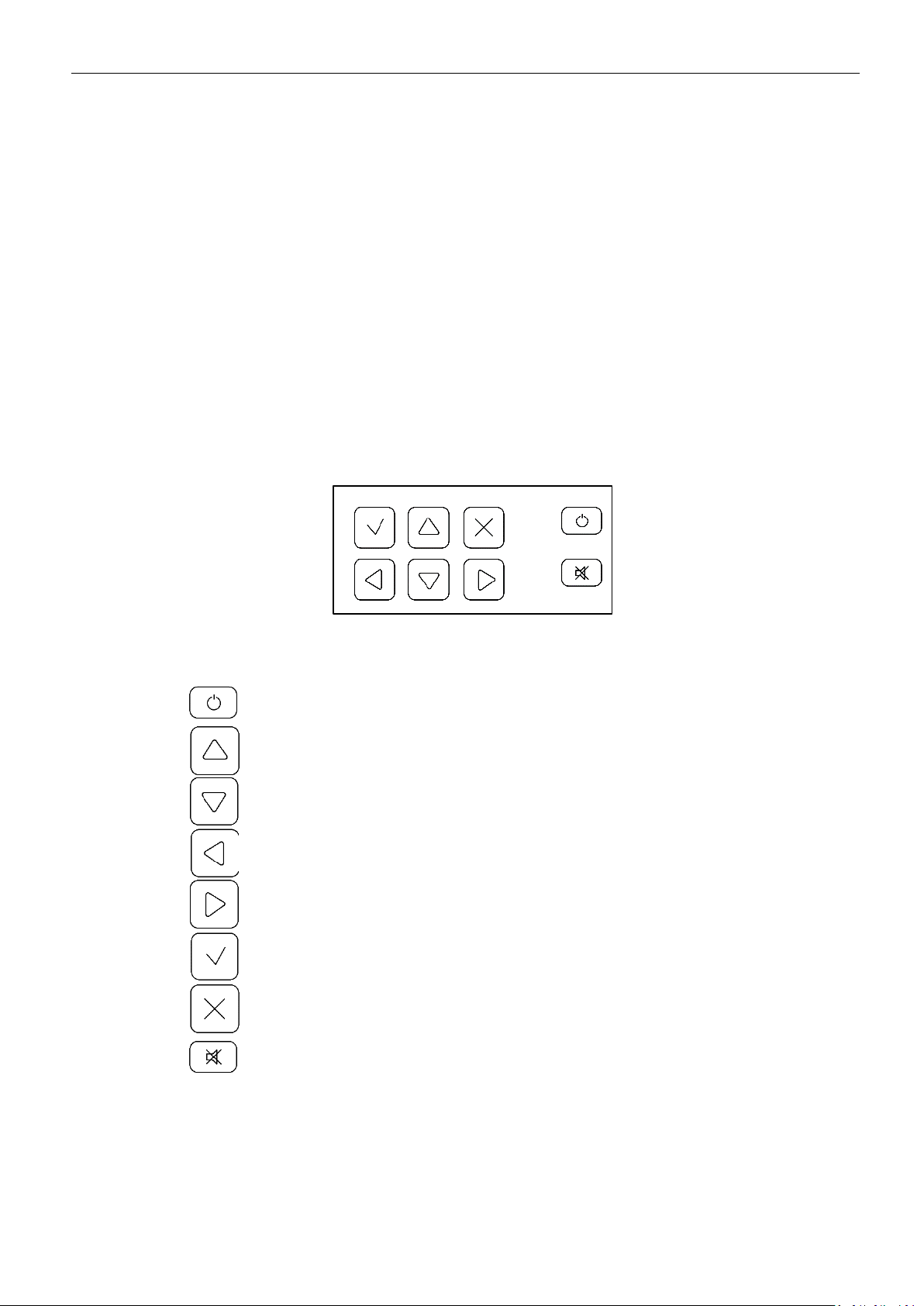
There is a keypad on the front panel for operation and menu navigation.
Keypad assignment:
- power on/off/reboot;
- up;
- down;
- left;
- right;
- confirmation (main mode –cannel information request);
- cancel/back (main mode –menu request);
- emergency mute (handshaking).
P O WE R O N /O FF / RE B OO T
5
MRBP.424321.001G2 Version 1.0 15/06/2020
1POWER ON/OFF/REBOOT
1.1 FIRST START/SET-UP
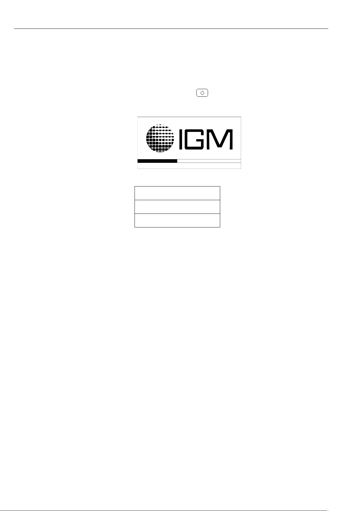
To power EMI-SSD-1M control on, after on-site mounting and/or new detectors connection
according to this UM, it is necessary to push the button on the control unit keypad, the loading
window appears on the display:
After the loading, the following message appears on the display:
↑
NO CHANNELS ENGAGED!
12:50↓
This message means it is necessary to perform channels tuning and connection.
EMI-SSD-1M control unit settings complete list can be found in the guide sections:
- «SETTINGS»;
- «INTERNAL CHANNELS SETTINGS»;
- «EXTERNAL CHANNELS SETTINGS»;
- «ARCHIVING MODE SETTINGS».
At the first start default settings and methane channels configuration factory settings are
set, factory default settings and gas configurations are shown Appendix B and C.
Minimal settings array essential for internal channel connection:
- date and time selection;
- current loop connection diagram selection;
- target gas selection.
Minimal settings array essential for external channel connection:
- date and time selection;
- device model selection;
- enter network address;
- interface RS-485 port settings.
After successful channels connection, «MAIN OPERATION MODE»appears on the display.
P O WE R O N /O FF / RE B OO T
6
MRBP.424321.001G2 Version 1.0 15/06/2020
1.2 RECLOSINGS/REPEATED SET-UPS
In case when the work with EMI SSD-1M control unit was previously carried out, the detec-
tors and channels settings didn’t change, it is necessary to press the button on the keypad to
turn the device on, loading window is displayed. After loading the following message is displayed:
01:SN09501668
↑
CHANNAL INITIALIZATION
CxHy % LFL 12:50
↓
This message means that the channel is preparing for work. Channel initialization mean time
is no longer than 130 seconds, after that «main operation mode»is displayed.
1.3 CHANNELS REBOOT
To reboot internal channels or one of internal channels it is necessary to enter «MENU»→
«CHANNEL REBOOT». The menu «INTERNAL CHANNELS REBOOT»is displayed.
INTERNAL CHANNELS REBOOT
Channel 1 Sn09501668
Channel 2 ----
Channel 3 ----
Channel 4 ----
Channel 5 ----
Channel 6 ----
Channel 7 ----
Channel 8 ----
REBOOT ALL
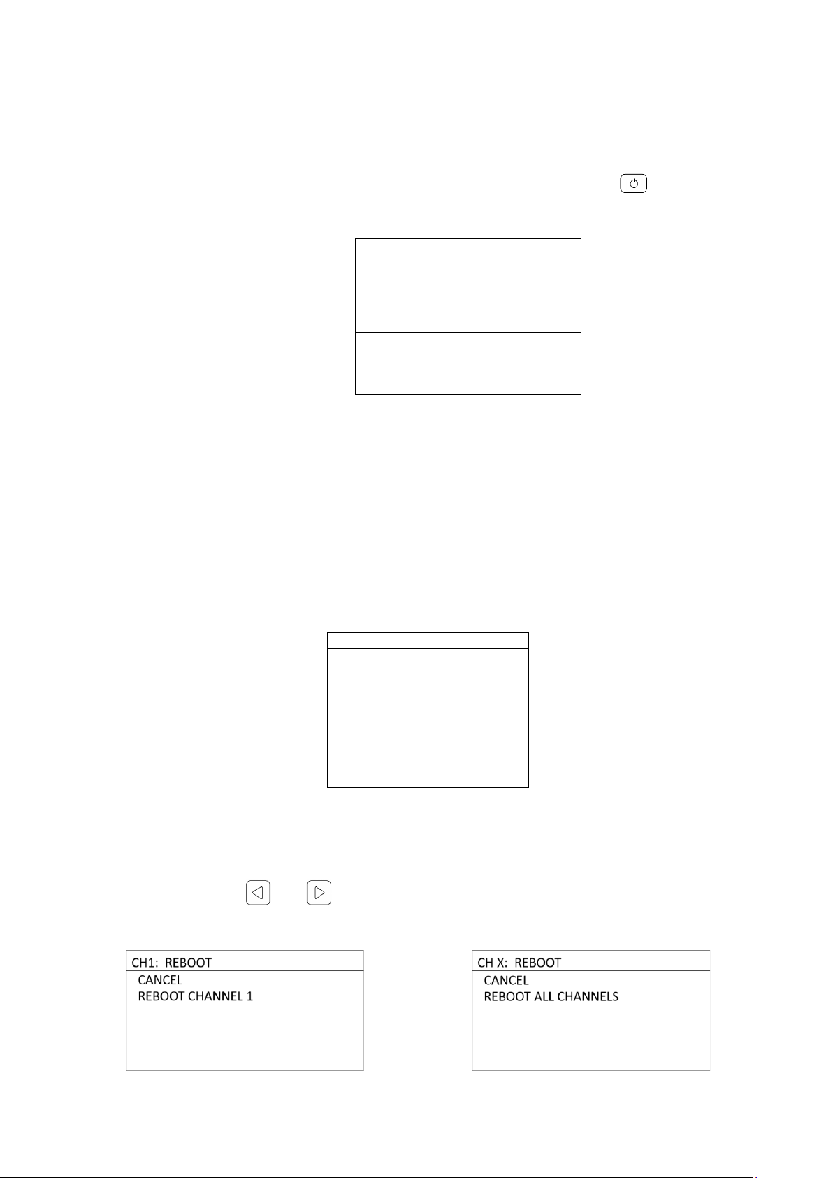
Then it is necessary to select a channel on the list, that is to be rebooted, or, if it is necessary
to reboot all the channels, select the menu option «REBOOT ALL». Menu «REBOOT»is displayed.
Using buttons and it is possible to review the channel brief information: position,
channel state.

P O WE R O N /O FF / RE B OO T
7
MRBP.424321.001G2 Version 1.0 15/06/2020
The following messages are displayed during the reboot confirmation:
These messages mean reboot is successful.
1.4 CONTROLLER REBOOT
To reboot EMI-SSD-1M control unit, it is necessary to push the button on the keypad,
the menu «WORK COMPLETION»is displayed.
WORK COMPLETION
REBOOT
POWER OFF
After menu «REBOOT»selection, the following message is displayed:
WORK COMPLETION
CONTROLLER REBOOT…
This message means reboot is in. Reboot mean time is 3-5 s, after which the load window
and then the initialization window is displayed. After the successful control unit reboot, «main opera-
tion mode»is displayed.
1.5 POWER OFF
To power EMI-SSD-1M control unit off it is necessary to push the button on the keypad,
menu «WORK COMPLETION»is displayed.
WORK COMPLETION
REBOOT
POWER OFF

P O WE R O N /O FF / RE B OO T
8
MRBP.424321.001G2 Version 1.0 15/06/2020
After menu «POWER OFF»selection, turning off window is displayed:
Power off mean time is 3-5 s, after which the control unit display blinks off and sensors pow-
er supply turns off.
M A IN O P ER AT IO N M O DE /M EN U
9
MRBP.424321.001G2 Version 1.0 15/06/2020
2MAIN OPERATION MODE/MENU
2.1 MAIN OPERATION MODE
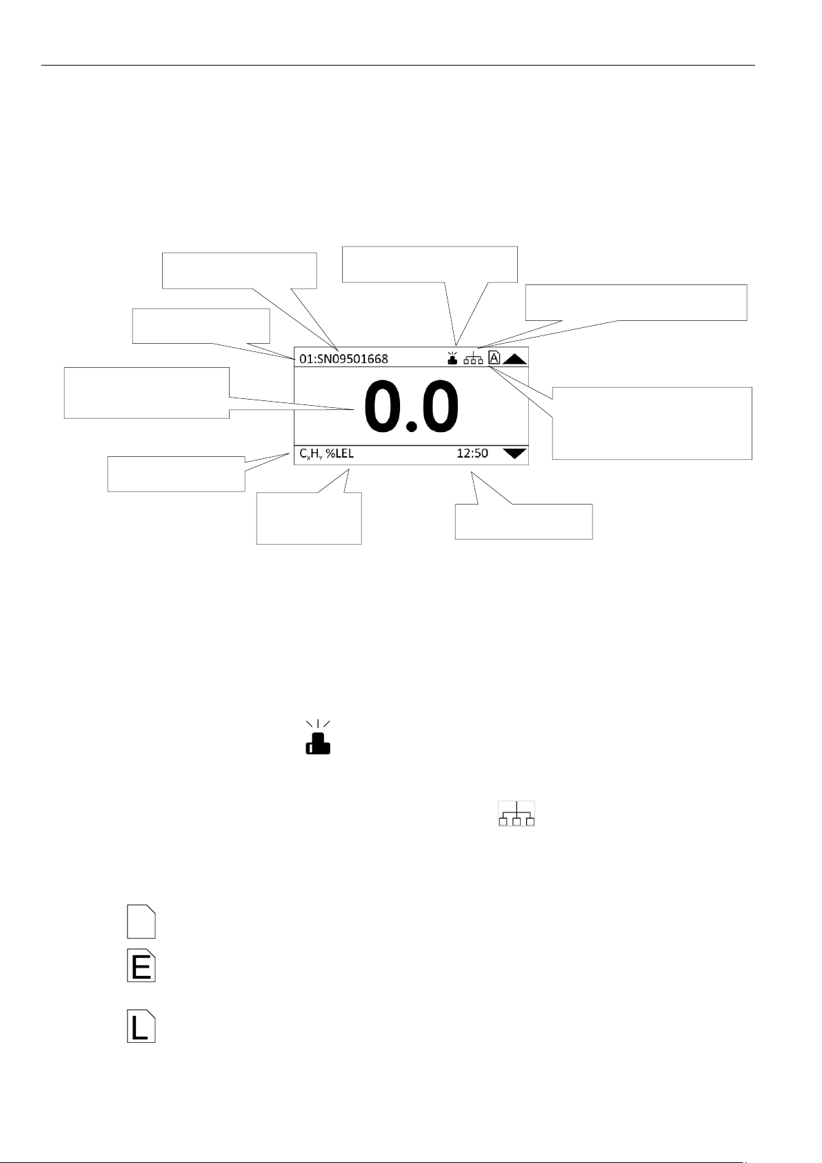
«Main operation mode»- EMI-SSD-1M control unit operation mode displaying the following
information:
•Current concentration value of the channel;
•Set target gas and its measurement units;
•Current channel number;
•Sensor position (set in channel settings);
•Current time;
•New contingency icon (disappears after new record review in the contingencies
menu);
•Data exchange with the control unit via RS-485 icon (disappears in 5 seconds after
data exchange with the control unit completion)
•Archiving on SD-card mode on icon:
- SD card is not found, LED «ALARM»flashes 3 times every 2 s);
- SD card record error;
- SD card record protection enabled;
Sensor position
Channel number
Current concentra-
tion value
Contingency
Data archiving on SD-card
mode
Data exchange via RS-485
Current time
Measure-
ment unit
Gas type

M A IN O P ER AT IO N M O D E/ M EN U
10
MRBP.424321.001G2 Version 1.0 15/06/2020
- data archiving on SD card mode. Data is recorded correctly.
By using buttons and channel is changed.
To review measured channel current information, it is necessary to push the button .
01:SN09501668
GAS: C3H8
VALUE, %LFL: 0.0
BLANKING ZONE: 0.0
THRESHOLD 1: 10.0
THRESHOLD 2: 20.0
MAX.VALUE: 100.0
MIN.VALUE: 0.0
THRESHOLD 1 HYSTERESIS: 0.0
THRESHOLD 2 HYSTERESIS: 0.0
THRESHOLD 1 RESET: AUTO
THRESHOLD 2 RESET: AUTO
CL CONNECTION: PASS.2wires
CURRENT, mA: 4,000
In the top left corner is the channel number and sensor item tag; hereunder is the present
channel information.
To return to the «main operation mode» press button or .
2.2 MENU
To change control unit or channels settings, it is necessary to enter the device’s «MENU»,
that requires pressing the button in the «main operation mode».
MENU
CONTINGENCIES
CHANNELS REBOOT
SETTINGS
CHANNELS SETTINGS
ARCHIVING SETTINGS
DEVICE INFO
For menu navigation use buttons and .
Necessary section selection –.
Quit the menu - .
Operation modes, signaling and relay actuations are described in the Appendix D.

C O NT IN G EN CI E S A R CH IV E D IS P LA Y
11
MRBP.424321.001G2 Version 1.0 15/06/2020
3CONTINGENCIES ARCHIVE DISPLAY
To review the contingencies archive it is necessary to enter «MENU»→«CONTINGENCIES».
In the «CONTINGENCIES» menu in the top right corner is the number of contingencies regis-
tered, hereunder is the information about each one, precisely:
•«RECORD #» - number of the record in the contingency archive;
•«DATE» - contingency registration date;
•«TIME» - contingency registration time;
•«CHANNEL/CONTROLLER»- number of the channel or controller;
•«STATUS» - contingency trigger.
Go to the next/previous record using buttons and .
Registered contingencies summary for the controller:
•«REBOOT» - controller EMI-SSD-1M reboot by the user;
•«TURN OFF»- EMI-SSD-1M control unit turn off by the user;
•«TURN ON»- EMI-SSD-1M control unit turn on;
•«CONTINGENCIES ARCHIVE CLEARING»- contingencies archive clearing by the user;
•«LOADER LOGIN»- controller «Loader»login;
•«SOFTWARE UPDATED»EMI-SSD-1M control unit Software update from «Loader»pro-
gram;
•«SOFTWARE UPDATE ERROR»error during Software updating;
•«RESET ALL SETTINGS»- control unit EMI-SSD-1M factory reset from «Loader»program;
Registered contingencies summary for the channels:
•«POWER SUPPLY REBOOT» - power supply reboot by the user;
•«POWER SUPPLY SC» - channel power supply short circuit;
•«CHANNEL MAINTENANCE» - channel maintenance;
•«SENSOR BREAKOUT»- sensor breakout;
•«THRESHOLD 1 EXCEEDED»- threshold 1 exceeded;
•«THRESHOLD 2 EXCEEDED»- threshold 2 exceeded;

C O NT IN G EN CI E S A R CH IV E D IS P LA Y
12
MRBP.424321.001G2 Version 1.0 15/06/2020
•«MEASUREMENT RANGE EXCEEDED» - measurement range exceeded;
•«CL SHORT CIRCUIT» - channel current loop short circuit.
Contingencies more detailed description is shown in Appendix D.
S E T TI NG S
13
MRBP.424321.001G2 Version 1.0 15/06/2020
4SETTINGS
To select the settings, it is necessary to enter «MENU»→«SETTINGS».
SETTINGS
DATE AND TIME
COMMUNICATION
DISPLAY
ACCESS
CONTINGENCIES ARCHIVE CLEARING
DEFAULT SETTINGS
In the menu «SETTINGS» it is possible to set/change the following settings:
•«DATE AND TIME» - current date and time selection;
•«COMMUNICATION»- communication parameters selection;
•«DISPLAY» - display parameters selection;
•«ACCESS» - access settings;
•«CONTINGENCIES ARCHIVE CLEARING» - contingencies archive clearing;
•«DEFAULT SETTINGS» - factory default.
Factory settings parameters –Appendix B.
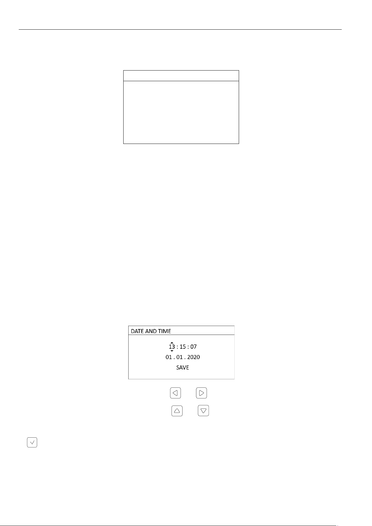
4.1 DATE AND TIME SELECTION
To select current date and time it is necessary to enter «MENU»→«SETTINGS» →«DATE
AND TIME».
Edited category is chosen by using the buttons and .
The parameter is changed by using the buttons and .
To apply and save the set date and time, it is necessary to select "SAVE" and push the button
.
D E VI C E T UNI N G
14
MRBP.424321.001G2 Version 1.0 15/06/2020
4.2 COMMUNICATION SETTINGS
To select the communication settings, it is necessary to enter «MENU»→«SETTINGS» →
«COMMUNICATION».
COMMUNICATION
NETWORK ADDRESS: 1
RATE, baud 19200
SAVE
In the «COMMUNICATION»menu it is possible to set the network address and baud rate for
the RS-485 interface.
The appearance of an asterisk in the upper line of the display - "COMMUNICATION*" means
that the values of the network address and /or rate have been changed. To apply and save the set
values, it is necessary to select "SAVE". The asterisk on the top line disappears after saving the com-
munication settings.
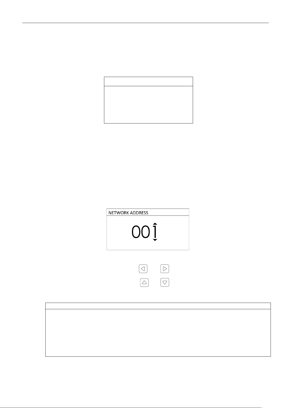
4.2.1 «NETWORK ADDRESS»
In the «NETWORK ADDRESS» menu it is possible to set the network address value 1 to 247.
Edited category is chosen by using the buttons and .
The parameter is changed by using the buttons and .
4.2.2 «RATE»
RATE
1200
2400
4800
9600
19200
34800
57600
115200
In the «RATE» menu it is possible to select one of the baud rates.
S E T TI NG S
15
MRBP.424321.001G2 Version 1.0 15/06/2020
4.3 DISPLAY SETTINGS
To select display settings, it is necessary to enter «MENU»→«SETTINS» →«DISPLAY».
DISPLAY
AUTO-QUIT THE MENU, s:
60
CHANGE INTERVAL, s:
5
BRIGHTNESS, %:
80
SAVE
In the «DISPLAY» menu it is possible to set/change the following settings:
•«AUTO-QUIT FROM THE MENU» - auto logout from the menu in the «main operation
mode»time interval;
•«CHANGE INTERVAL» - displayed channel in the «main operation mode»auto-change
time interval set;
•«BRIGHTNESS» - display brightness settings.
The appearance of an asterisk in the upper line of the display - "DISPLAY*" means that the
settings have been changed. To save the set values, it is necessary to select "SAVE". The asterisk on
the top line disappears after saving the set display parameters.
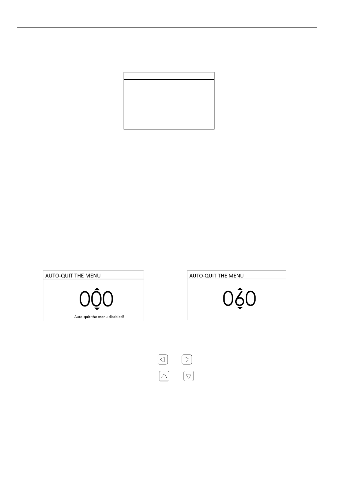
4.3.1 «AUTO-QUIT THE MENU»
Interval range from 20 to 255 seconds. Zero value of the interval disables auto-quit the
menu.
Edited category is chosen by using the buttons and .
The parameter is changed by using the buttons and .
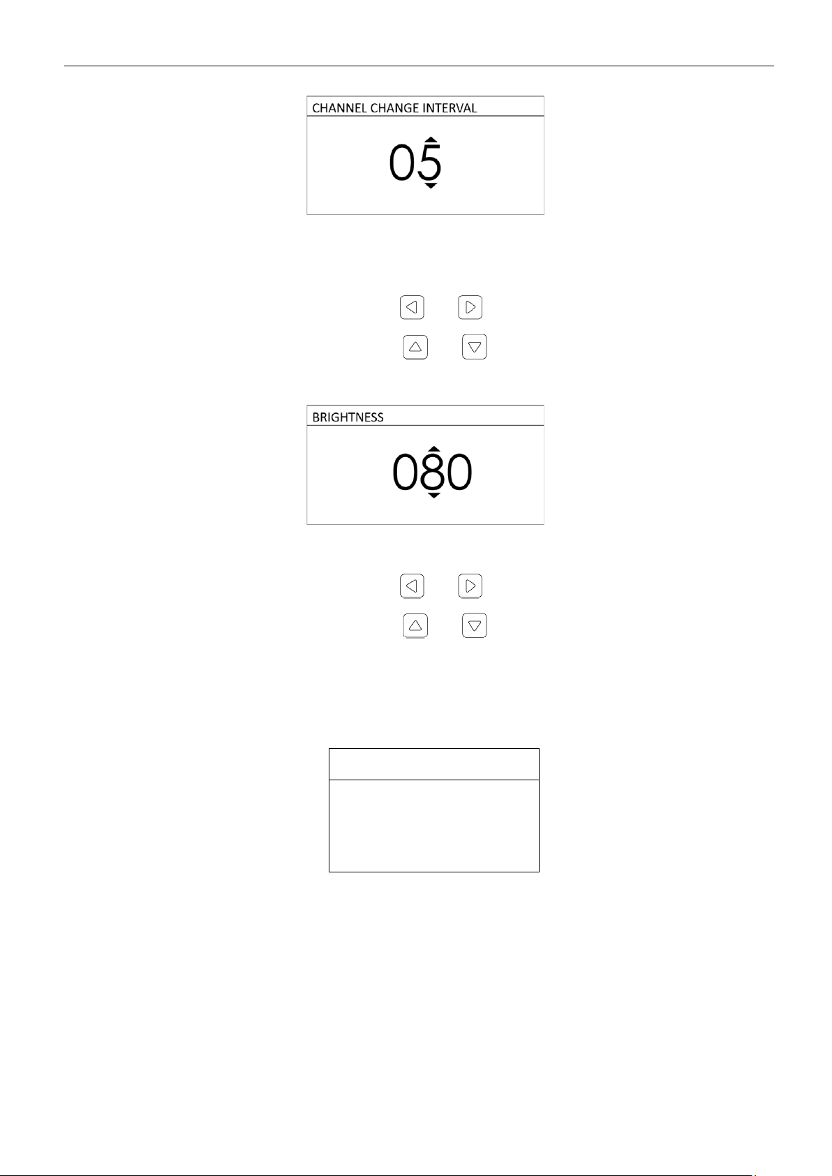
4.3.2 «CHANNEL CHANGE INTERVAL»
D E VI C E T UNI N G
16
MRBP.424321.001G2 Version 1.0 15/06/2020
Interval range from 0 to 60 seconds. Zero value of the interval disables displayed channel au-
to-change.
Edited category is chosen by using the buttons and .
The parameter is changed by using the buttons and .
4.3.1 «BRIGHTNESS»
Display brightness change from 1 to 100%.
Edited category is chosen by using the buttons and .
The parameter is changed by using the buttons and .
4.4 ACCESS SETTINGS
To select access settings, it is necessary to enter «MENU»→«SETTINGS» →«ACCESS».
ACCESS
CHANGE PASSWORD
In the «ACCESS»menu it is possible to set/change the access password for the following
menu sections:
•«SETTINGS»;
•«CHANNELS SETTINGS»;
•«ARCHIVING SETTINGS»;

S E T TI NG S
17
MRBP.424321.001G2 Version 1.0 15/06/2020
•«SOFTWARE UPDATE»(in the «Loader»mode).
To change the password, it is necessary to select «CHANGE PASSWORD» in the «ACCESS»
menu.
Set bit is selected by using the buttons and .
Value is changed by using the buttons and .
To apply and save the password it is necessary to select «SAVE» and push the button .
After successful saving of the new password, the message is displayed:
CHANGE PASSWORD
new password
SAVED!
To disable settings password security, it is necessary to save the value «0 0 0 0» in the
«CHANGE PASSWORD» menu, the following message is displayed:
CHANGE PASSWORD
password security
DISABLED!

D E VI C E T UNI N G
18
MRBP.424321.001G2 Version 1.0 15/06/2020
4.5 CONTINGENCIES ARCHIVE CLEARING
To clear the contingencies archive it is necessary to enter «MENU»→«SETTINGS» →«CON-
TINGENCIES ARCHIVE CLEARING».
CLEAR CONTINGENCIES ARCHIVE
CANCEL
CLEAR CONTINGENCIES ARCHIVE
In the «CONTINGENCIES ARCHIVE CLEARING» it is possible to confirm or cancel contingen-
cies archive clearing.
4.6 DEFAULT SETTINGS
To set the default settings it is necessary to enter «MENU»→«SETTINGS» →«DEFAULT
SETTINGS».
DEFAULT SETTINGS
CANCEL
APPLY AND SAVE
It is possible to cancel or apply and save factory default.
I N TE RN A L C H AN N EL S S E TT I NG S
19
MRBP.424321.001G2 Version 1.0 15/06/2020
5INTERNAL CHANNELS SETTINGS
To select internal channels settings, it is necessary to enter «MENU»→ «CHANNELS SET-
TINGS»→ «INTERNAL CHANNELS».
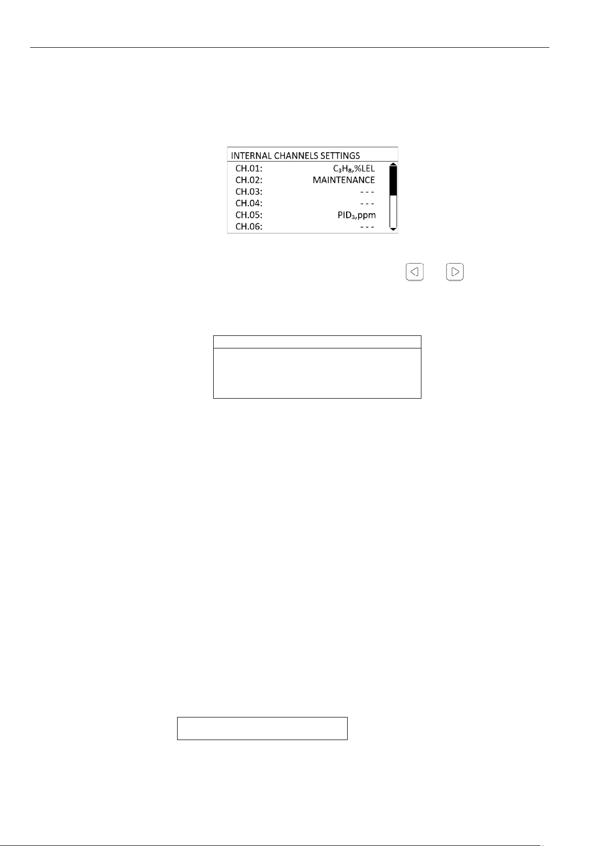
The list of internal channels is shown in the «INTERNAL CHANNLES SETTINGS» menu. It is
possible to see brief information about a channel by using the buttons and : gas, measure-
ment units, position, channel state. After the channel selection, the channel settings menu is dis-
played.
CH1: TUNING
MAINTENANCE: DISABLED
CONFIGURATION
INPUT CALIBRATION
CHANNEL FACTORY DEFAULTS
The number of the channel is shown in the top left corner of the display (C1-C8).
In the «SETTINGS»menu it is possible to set/change the following channel settings:
•«MAINTENANCE» - maintenance mode switching on/off;
•«CONFIGURATION» - configuration change;
•«INPUT CALIBRATION» - input calibration parameters change;
•«CHANNEL FACTORY DEFAULT» - factory default settings.
5.1 CHANNEL MAINTENANCE MODE SWITCHING ON/OFF
At turning «MAINTENANCE»mode on any contingencies are bypassed, i.e. relay, sound and
LED signalizations don’t go off. This mode is intended for maintenance service or trouble-shooting of
the detector connected to the channel.
To switch on/off channel maintenance mode it is necessary to enter «MENU»→ «CHANNELS
SETTINGS»→ «INTERNAL CHANNELS» → «CHANNEL 0Х» →«MAINTENANCE».
CH1: MAINTENANCE

I N TE RN A L C HA N N EL S S ET TI N GS
20
MRBP.424321.001G2 Version 1.0 15/06/2020
In the «MAINTENANCE» mode it is possible enable or disable selected channel maintenance.
5.2 CHANNEL CONFIGURATION CHANGE
To change channel configuration, it is necessary to enter «MENU» → «CHANNELS SETTINGS»
→ «INTERNAL CHANNELS» → «CHANNEL 0X»→«CONFIGURATION».
CH1: CONFIGURATION
CL CONNECTION:
PASS.2wires
POSITION:
SN09501668
GAS TYPE:
C3H8
MEASUREMENT UNIT:
%LFL
MIN.VALUE:
0.0
MAX.VALUE:
100.0
BLANKING ZONE:
1.0
THRESHOLD 1 VALUE:
10.0
THRESHOLD 1 HYSTERESIS:
0.0
THRESHOLD 1 RESET:
AUTO
THRESHOLD 2 VALUE:
20.0
THRESHOLD 2 HYSTERESIS:
0.0
THRESHOLD 2 RESET:
AUTO
SAVE
In the «CONFIGURATION» menu, it is possible to change/set the following parameters:
•«CL CONNECTION» - current loop connection diagram selection;
•«POSITION» - detector position name;
•«GAS TYPE» - target gas type selection;
•«MEASUREMENT UNIT» - gas concentration measurement unit selection;
•«MIN. VALUE» - measurement range minimal value set, corresponds to a 4 mA scale mark
on the current loop;
DISABLE
ENABLE
Table of contents
Other IGM Dust Collector manuals


Popular Dust Collector manuals by other brands

Trelawny
Trelawny A70X Operation and maintenance manual

General
General 10-030CF M1 Setup & operation manual

Donaldson
Donaldson Downflo Evolution DFE 2-8 Installation, operation and maintenance manual

Pulmic
Pulmic DRAGON 7 POWER Operator's handbook

Makita
Makita DX05 instruction manual

Jet
Jet DC-1200 operating instructions


Hafco Woodmaster
Hafco Woodmaster DC-90 instruction manual

Dust Right
Dust Right 650 CFM instruction manual

Donaldson Torit
Donaldson Torit DCE 2000 Series Installation, operation and maintenance manual

Grizzly
Grizzly G0548 parts manual

RoboVent
RoboVent VENTBOSS G130 owner's manual

Oneida Air Systems
Oneida Air Systems V-System XXVS300035 owner's manual