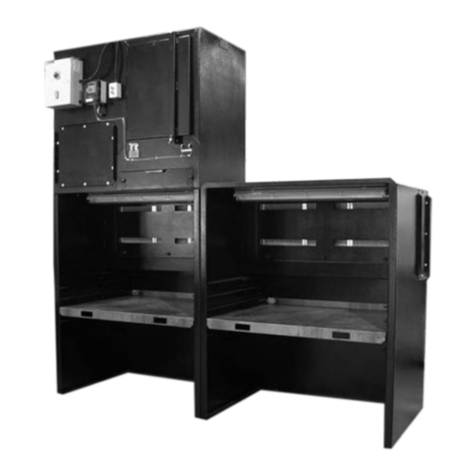
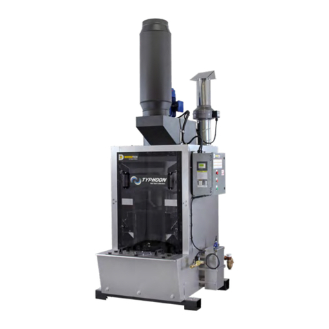
DIVERSITECH Typhoon TY-8000 Manual

READ AND SAVE THESE INSTRUCTIONS
Operation & Maintenance Manual
TYPHOON CENTRAL DUST COLLECTOR
Visit our Website for more information on this product
www.diversitech-air.com www.diversitech.ca
1200 55th Avenue, Montreal, Quebec H8T 3J8

TABLE OF CONTENTS
SECTION 1 – SAFETY........................................................................................................................................................................................................................................................................................................3
SECTION 2 – GENERAL PRODUCT INFORMATION...................................................................................................................................................................................................................................4
SECTION 3 – PRODUCT SHIPMENT ...................................................................................................................................................................................................................................................................... 6
SECTION 4 – PRODUCT RECEIPT AT THE DESIGNATED DELIVERY POINT.......................................................................................................................................................................... 6
SECTION 5 – UNLOADING AND HANDLING ...................................................................................................................................................................................................................................................7
SECTION 6 – STORAGE AND PROTECTION................................................................................................................................................................................................................................................10
SECTION 7 – SITE PREPARATION........................................................................................................................................................................................................................................................................10
SECTION 8 – ASSEMBLY AND INSTALLATION..........................................................................................................................................................................................................................................11
8.1 Assembling and installing the structure ...........................................................................................................................................................................................................................................11
8.2 Foundation Installation and Levelling .................................................................................................................................................................................................................................................11
8.3 Assembly of Hopper to Cleaning Sections....................................................................................................................................................................................................................................12
8.4 Assembly of Middle Section to Clean Air Transition Section............................................................................................................................................................................................. 14
8.5 Assembly of Hydrogen Vent Fan .........................................................................................................................................................................................................................................................15
8.6 Assembly of Motor and Blower to Clean Air Transition Section......................................................................................................................................................................................15
8.7 Water Inlet and Solenoid Valve..............................................................................................................................................................................................................................................................16
8.8 Drain Connection for Typhoon Central Dust Collector ..........................................................................................................................................................................................................18
8.9 Ductwork Installation .....................................................................................................................................................................................................................................................................................18
SECTION 9 – WATER LEVEL CONTROL OPTIONS .................................................................................................................................................................................................................................19
SECTION 10 – START-UP & OPERATION........................................................................................................................................................................................................................................................19
10.1 Principles of Operation .............................................................................................................................................................................................................................................................................19
10.2 Controls...............................................................................................................................................................................................................................................................................................................19
10.3 Water Level Monitoring ............................................................................................................................................................................................................................................................................20
10.4 Alarms..................................................................................................................................................................................................................................................................................................................20
10.5 Level Set Point................................................................................................................................................................................................................................................................................................21
10.6 Regular Operation........................................................................................................................................................................................................................................................................................21
10.7 Reprogramming Water Level Sensor.............................................................................................................................................................................................................................................21
SECTION 11 – MAINTENANCE................................................................................................................................................................................................................................................................................23
11.1 Record Keeping............................................................................................................................................................................................................................................................................................23
11.2 Pre-Use Checklist.........................................................................................................................................................................................................................................................................................23
11.3 Water Level Control Box .........................................................................................................................................................................................................................................................................23
11.4 Typhoon Central Dust Collector Housing....................................................................................................................................................................................................................................23
11.5 After Filters ........................................................................................................................................................................................................................................................................................................23
11.6 Exhaust Fan......................................................................................................................................................................................................................................................................................................23
11.7 Replacement Part Stock..........................................................................................................................................................................................................................................................................24
11.8 Routine Maintenance Schedule.........................................................................................................................................................................................................................................................24
SECTION 12 – TROUBLESHOOTING..................................................................................................................................................................................................................................................................24
12.1 Reduction in airflow at exhaust hoods...........................................................................................................................................................................................................................................24
12.2 Reduced dust collection efficiency ..................................................................................................................................................................................................................................................25
12.3 Water entrainment in fan discharge.................................................................................................................................................................................................................................................25
12.4 Troubleshooting Procedure..................................................................................................................................................................................................................................................................26
APPENDIX 1A – ELECTRICAL DIAGRAM [240/415v] 3-Phase Power........................................................................................................................................................................................ 27
APPENDIX 1B – SETTING SENSING WINDOW............................................................................................................................................................................................................................................ 28
NOTES........................................................................................................................................................................................................................................................................................................................................29
TERMS AND CONDITIONS TO SALES ORDERS.................................................................................................................................................................................................................................30,31
Back Cover..............................................................................................................................................................................................................................................................................................................................32
Revised October 2019 [E N]

3
SECTION 1 - SAFETY
1.1 Safety statement
1.2 Safe working practices and staff training
1.3 Dust explosion hazard
1.3.1 NFPA 654 and referenced codes and standards
The air cleaning equipment supplied by Diversitech ranges from very large multiple-component assemblies which require significant and complex,
rigging, handling and assembly on-site, to small compact assemblies that are easily handled and maneuvered. In addition to size, many of the dust
collectors will require electrical connections, compressed air connections, and will feature high speed rotating equipment.
At all times, when dealing with industrial equipment such as dust collection equipment personnel safety must be the highest priority of all involved,
from riggers, installers, operators, users, and maintenance personnel. Those responsible on-site shall review the details of the equipment beforehand
and develop a plan for dealing with all stages of the installation from receipt of the equipment on-site to start-up, commissioning, and hand-over. All
applicable health, safety, and environmental (“HSE”) rules, regulations and legislation shall be fully complied with at all times.
By its very nature the Typhoon Central Dust Collector is intended to be used to capture airborne particulate matter, otherwise known as dust.
Many dusts have the potential to be explosive. Dust explosions constitute a serious industrial hazard and may result in death, serious injury, and
devastating property damage. It is the responsibility of the user to identify the nature of the dust generated during any process or activity, whether or not
it poses an explosive hazard, and to properly mitigate this hazard.
Except as otherwise expressly provided in writing, Diversitech makes no representation or warranty in connection with explosion hazard equipment,
including, but not limited to, the necessity or effectiveness of explosion hazard equipment or to the design, installation, operation, and performance of
such equipment.
The basic standards for dealing with explosive dust applications are published by the National Fire Protection Agency (“NFPA”). The user shall be fully
conversant with the provisions of the particular codes and standards that apply to the specific application and equipment used, and shall comply in full
with all of the requirements of the applicable codes and standards.
The owner shall review and comply with NFPA 654: Standard for the Prevention of Fire and Dust Explosions from the Manufacturing,
Processing, and Handling of Combustible Particulate Solids, and those other documents referenced therein. NFPA 654 pertains to “all
phases of manufacturing, processing, blending, conveying, repackaging, and handling of combustible particulate solids or hybrid mixtures,
regardless of concentration or particle size, where the materials present a fire or explosion hazard”. The purpose of the standard “is to prescribe
technical requirements for safety to life and property from fire and explosion and to minimize the resulting damage from a fire or explosion”.
The user shall be fully conversant with the provisions of NFPA 654 and shall comply in full with all of its requirements and those of all applicable
referenced codes and standards.
Note that NFPA 654 does not apply to the specific applications or materials covered by the other NFPA documents unless specifically
referenced by those documents.
Diversitech is fully committed to the safety of its employees and those of its customers. In this spirit the following guidelines are offered for the
consideration of those responsible:
• All personnel shall receive safety training specific to the site, the task, and the conditions under which the work will be conducted.
• All personnel shall be equipped with appropriate safety apparel and equipment, such as clothing, footwear, hard-hats, gloves, ear protection,
eye protection, and safety harness.
• All personnel involved in any stage of the process shall have been trained for the tasks in which they will be involved and at all times shall be
under the direct supervision of experienced supervisors and managers.
• All personnel shall be equipped with appropriate tools and equipment to safely and efficiently complete their task.
• Adequate lighting shall be supplied at all times while work is being conducted.
• A work perimeter shall be set up to define the limits of the area within which the work will be conducted and outside which there will be
no threat to the safety of personnel or plant. The perimeter shall be taped-off and marked appropriately to prevent accidental ingress of
uninvolved personnel or equipment. When the work area impedes into existing access ways or traffic routes for which no practical alternative
is available, barriers, wardens and flaggers shall be employed to safely control crossing traffic and personnel.
• At any time only those personnel directly involved in completing the task at hand shall be allowed within the work perimeter.

4
1.3.2 NFPA 484, Light Metals
1.3.3 Other requirements
1.4 Electrical hazards
1.5 Rotating equipment
1.6 Safety guards
There are various methods for dealing with a dust explosion hazard. The Typhoon Central Dust Collector is particularly appropriate for the collection of
dust generated by the working of light metals such as aluminum, titanium and magnesium. These dusts are highly explosive and the Typhoon Central
Dust Collector uses water as a medium for neutralizing the development of a potentially explosive dust cloud and for eliminating the possibility of ignition.
The specific standard that applies to these applications is NFPA 484: Standard for Combustible Metals. This standard applies to “the production,
processing, finishing, handling, recycling, storage, and use of all metals and alloys that are in the form that is capable of combustion or explosion”. When
the Typhoon Central Dust Collector is used to collect dust from the working of light metals, the user shall be fully conversant with the provisions of NFPA
484 and shall comply in full with all of its requirements.
The use of a dust collector for the collection of explosive dust is only one part of a safe dust prevention and mitigation program. Dust shall not be
allowed to accumulate or build up on the surfaces of the dust collector, on the air intakes or in the surrounding area. The owner’s attention is directed
particularly to the “Housekeeping” chapters in NFPA 654 (Chapter 8 in the 2013 edition) or NFPA 484 (Chapter 7 in the 2015 edition). If any of the
other codes and standards referenced above applies, consult the appropriate chapters in those documents.
The editions referenced here were current at the time of writing. Be aware that they may have changed. When referring to NFPA standards, the user
shall ensure that they are working with the most current edition.
For information on NFPA®standards, go to http://www.nfpa.org/. NFPA provides free on-line read-only access to its codes and standards. Standards
may also be purchased.
Before doing any work on the Diversitech equipment make sure that all potential electrical hazards have been identified and that all electric current
connected to the equipment, and to any connected or associated equipment, has been properly disconnected and securely locked-out to prevent
accidental reconnection prior to completion of the work. All electrical work shall be done in full accordance with the current edition of NFPA 70, the
National Electrical Code, and all other applicable laws, rules, and regulations. All electrical work shall be performed by a licensed electrician. Only
original Diversitech parts shall be used as replacements for ongoing maintenance and repair.
The Typhoon Central Dust Collector incorporates a fan which is close-coupled and installed on top of the Typhoon Central Dust Collector, or installed
separately (typically ground mounted) and ducted to the outlet of the Typhoon Central Dust Collector. The fan impeller (fan wheel) may rotate at
nominal speeds approaching 3600 rpm and has the potential to cause severe injury. The fan impeller can be accessed through the collector from
inside the cabinet if the moisture eliminator is removed, from the outside of the collector through the collector discharge, or from the connecting inlet or
outlet ductwork. All due care should be exercised to avoid any contact with the operating fan. Under no circumstances should the fan ever be allowed
to operate when any of the access panels on the dust collector, silencer, or connecting ductwork have been removed. The fan must be disconnected
and locked out prior to the performance of any maintenance work, see paragraph 1.4.
The dust collector cabinet prevents access to the fan inlet. All access panels and ducts shall remain bolted in place while the fan is operating. Prior to
the removal of any access panel or ducts the electrical power to the collector shall be disconnected and locked out, see 1.4 and 1.5.
After electrical power is disconnected the fan impeller will continue to rotate for a period of time before coasting to a stop. Do not access the fan until
the fan wheel has come to a complete stop.
The Typhoon Central Dust Collector is a wet dust collector which uses water as the medium to separate dust from air by means of mixing through
a baffle and basin. When installed and operated properly, the Typhoon Central Dust Collector operates automatically and will require very little
maintenance. However, as is the case with any mechanical equipment, it should be operated, maintained and serviced in accordance with these
instructions to ensure long life and trouble free performance and use.
The dust generated by the particular operation for which the Typhoon Central Dust Collector is employed is drawn into the collector through the inlet
ductwork, into a water bath, and then through Diversitech’s unique baffle section which through a combination of induced aerodynamic and hydrostatic
forces causes the dust to mix thoroughly with the water and separate from the air. The cleaned air is then emitted from the dust collector through the
fan and the separated dust settles to the bottom of the water bath. The dust forms a sludge which is then periodically removed from the collector.
The Typhoon Central Dust Collector can only be operated when it is filled with water to the correct level. A low water level would result in by-pass of
unfiltered air. Automatic filling allows the Typhoon Central Dust Collector to run continuously and in case of a failure event cut-out devices prevent
operation of the fan if the water level is too low.
SECTION 2 - GENERAL PRODUCT INFORMATION
2.1.1 Description

5
Model
Inlet Collar
Diameter (in.)
Footprint Water
Weight (lbs)Width [a] Height [b] Length [c] Supply (in.) Drain (in.)
TY-8000 20 7’-7” 15’- 8” 7’-9” 1/4” NP T 2” NPT 4000
TY-10000 20 7’-7” 15’-8” 7”-9” 1/4” NPT 2” NPT 4000
TY-12000 20 7’-7” 15’- 8” 7’-9” 1/4” NPT 2” NPT 4000
2.1.2 Typhoon Central Dust Collector Dimensions
2.2 Purpose and intended use
2.2.2 Collection of other dry dusts
2.2.1 Collection of explosive dusts
The Typhoon Central Dust Collector is intended to be used to collect a wide range of dust produced in industrial applications. It is particularly effective
for the collection of dusts that are potentially explosive such as light metal dusts (aluminum, titanium, or magnesium) and coal dust, or dusts that are
damp, wet, sticky or oily. Contact Diversitech support at 1-800-361-3733 for assistance with your application.
The Typhoon Central Dust Collector can also be used to collect dust generated by the working of other metallic and non-metallic
materials that may not present an explosion hazard.
As mentioned, the Typhoon Central Dust Collector is primarily particularly effective for the collection of dust generated by the working of light
metals such as aluminum, titanium, and magnesium, and for the collection of other explosive dusts such as coal dust. Such dusts have the
potential to be highly explosive if not dealt with correctly.
The Typhoon Central Dust Collector neutralizes the threat of a dust explosion by encapsulating the captured dust in water and preventing the
development of both a dust cloud that might reach the explosive limit and of any potential ignition source.
It bears repeating here that the use of a dust collector for the collection of explosive dust is only one part of a safe dust prevention and mitigation
program. Dust shall not be allowed to accumulate or build up on the surfaces of the dust collector, on the air intakes or in the surrounding area.
The owner’s attention is directed particularly to the “Housekeeping” chapter in NFPA 484 (Chapter 7 in the 2015 edition) and in NFPA 654
(Chapter 8 in the 2013 edition).

6
2.2.3 Collection of damp, wet, oily or sticky dusts
2.3 Normal Operation
3.1 How the product ships
3.2 Items that ship separately
The Typhoon Central Dust Collector is an effective collector of dusts that are difficult or even impossible for other collectors, particularly dry collectors
such as cartridge and bag collectors, to collect. Damp, wet, sticky or oily dusts can clog the pores of paper and fabric media. In pulse clean or shaker
style self-cleaning dust collectors, these dusts will not release from the cartridges or bags, causing the dust collector to clog and quickly fail.
The Typhoon Central Dust Collector cleans the air by the combined action of centrifugal force and a thorough mixing of water and dust laden air.
The dust is separated from the air by means of a water curtain, created by the flow of air through a partially submerged stationary impeller (see
Figure 1). Air flowing through the impeller at a high velocity conveys water with it in a very turbulent sheet. Additional water is introduced at the
narrowest portion of the impeller through a specially designed slot in the bottom. Since there is a certain differential pressure through the impeller,
the water flows upward through the slot in an attempt to reach the water level on the clean air side. This water flow upward through the slot creates
increased interaction between the dust and water, thus, increased collection efficiency. Since the water flows upward in an attempt to reach the
water level on the clean air side of the impeller, the impeller opening can be decreased (resulting in higher differential pressure and collection
efficiency) by raising the water in the unit. This is accomplished by a unique and patented variable water level control box. The centrifugal force
exerted by the rapid changes in direction of flow causes the dust particle to penetrate the water film and become permanently trapped. (Figure 1)
The water in the reservoir is continually reused and since the water curtain is produced by the air flow, no pumps or nozzles are required. The
water level is maintained by the overflow weir in the control box as long as a small amount of fresh water is supplied through the make-up water
connection or by electrical controls that automatically add water, as needed to compensate for evaporation and water lost as the collected dust is
removed from the unit.
The Diversitech Typhoon Central Dust Collector is shipped with the base, cleaning, clean air, and motor-blower sections disassembled.
The people of Diversitech take pride in the quality of the products that we supply and it is our intention that our customer’s experience with our
products and services be positive and satisfying. This process begins at delivery. It is important to ensure that the product delivered is what was
ordered and that it arrives at its destination in perfect condition. Adequate preparation on the part of the buyer, together with a structured approach
to receipt and inspection, will ensure that if problems exist they are communicated swiftly and efficiently through the proper channels allowing them
to be resolved in the shortest possible time.
To reduce freight costs, Diversitech may ship items separately. The customer will be notified which equipment ships separately when the order is
placed. Items that ship separately should be set aside in an area that is clean, dry, and in a place where damage to the equipment will not occur,
see section 6 for information on storage and protection.
SECTION 3 - PRODUCT SHIPMENT
SECTION 4 - PRODUCT RECEIPT AT THE DESIGNATED DELIVERY POINT
4.1 Responsibilities of the customer or customer’s agent
4.2 Receiving
4.3 Inspection on arrival
Ensure all loading/unloading equipment and safety equipment is on site at the time of delivery. Safe and efficient operation of the collector depends on
proper installation. Know proper laws, codes and regulations before installation starts.
Remove crates, tarps, shipping straps, etc. along with any loose items or equipment before unloading the Diversitech Typhoon Central Dust Collector.
The Diversitech Typhoon Central Dust Collector is normally shipped by truck and should be checked for damage that may have occurred in route.
Compare the collector(s) received to the description and/or drawing of the collector(s) ordered. Immediately report any differences or missing items
from the order to Diversitech. Remove loose items or components before lifting the collector from the truck.
A qualified installation and service company should complete installation of the collector and accessories.

7
4.4 Damaged goods
5.1 Unloading
5.2 Handling
4.5 Missing goods
If there is any visible damage to the packaging or the equipment, notify the carrier and Diversitech before proceeding further and, if appropriate, file an
immediate claim with the carrier against such damage. Be aware that damage to packaging may indicate hidden damage to the product that is not
immediately discernable.
Digital color photographs must be taken of any damage to the packaging and the equipment immediately on discovery. The nature of any damage
must also be documented in writing. Adequate documentation will be critical to support any claims.
Contact Diversitech support at 1-800-361-3733 for claim filing procedure.
• Failure to lift the collector correctly can result in severe personal injury, property damage, or even death.
• Connect lifting sling to at least four cabinet lifting lugs, if possible, distributing the load evenly.
• Use clevises, not hooks, on lifting sling.
• Use of spreader bars is recommended on all lifting slings.
• Check the drawings of the specific Typhoon Central Dust Collector ordered for dimensions and weights to ensure proper lifting and
installation equipment.
• All lifting operations must be made in compliance with the relevant HSE legislation.
Only personnel experienced in handling equipment shall be employed for this task.
If lifted by its shipping pallet, attention must be paid to properly balancing the load and strapping it to the handling device. Care shall be taken
to ensure that the equipment is not dropped or subjected to any impact loads.
Any missing goods should be noted on the delivery receipt, and the carrier and Diversitech notified immediately.
Contact Diversitech support at 1-800-361-3733 for claim filing procedure.
SECTION 5 – UNLOADING AND HANDLING
5.3 Rigging and Hoisting instructions
Only personnel experienced in rigging and hoisting equipment shall be employed for this task.
It is recommended that each item of equipment remain on its pallet until it has been moved to its final installation location. The Typhoon Central Dust
Collector may be moved using a forklift to lift the product using its shipping pallet, if available.
The Typhoon Central Dust Collector also has lifting lugs mounted on the top. These may be used to hoist the product instead of lifting it using the
shipping pallet. All lifting lugs must be used when hoisting the product. When using the top mounted lifting lugs use spreader bars at all times.
Position the spreader bars so that the force applied to each lifting lug is vertical and not angled. Also make sure that lifting straps or cables do not
come into contact with any other part of the product to prevent the possibility of damage from abrasion. Before hoisting make sure that the load is
properly balanced. At the beginning of the lift, hoist the product slowly and carefully.
5.4 Flat Base Hoisting
Hoisting must be done from the hoist mounts. Appropriate hoisting procedure should be followed according to
section 5.3 Rigging and Hoisting Instructions.

8
5.5 Hopper Base Hoisting
Hoisting must be done from the hoist mounts. Appropriate hoisting procedure should be followed according to
5.3 Rigging and Hoisting Instructions
5.6 Middle Section Hoisting
Hoisting must be done from the hoist mounts. Appropriate hoisting procedure should be followed according to
5.3 Rigging and Hoisting Instructions

9
5.7 Top Section Hoisting
Hoisting must be done from the hoist mounts. Appropriate hoisting procedure should be followed according to
5.3 Rigging and Hoisting Instructions
5.8 Motor-Blower Hoisting
Hoisting must be done from the hoist mounts. Appropriate hoisting procedure should be followed according to
5.3 Rigging and Hoisting Instructions

10
• If not installed immediately, the equipment shall be retained and stored in a protective environment until immediately prior to
installation. This environment shall be clean, dry, and temperature and humidity-controlled.
• At all times the equipment shall be protected from exposure to weather and from standing water.
• All equipment shall be stored on its original shipping pallet so that it is elevated above grade.
• The equipment shall be clearly labelled and be stored in a location that is easily and readily accessible.
• If prolonged storage (greater than 30 days) is anticipated, the equipment shall be covered with plastic to prevent the accumulation of
surface dust and include the following:
• Motor shaft and flanges to be coated with easily removable rust preventative Tectyl No.502-C, or equal.
• Block all openings to prevent rodents and small animals from nesting inside.
• Insert silica gel desiccant in control boxes and motor junction boxes.
• Cover units completely to exclude dirt, dust, moisture, and other foreign materials. If possible, insert motor in strong, transparent plastic
bag. Attach moisture indicator to side of motor, place several bags of silica gel inside, then seal plastic bag. If motor cannot be placed
in plastic bag and relative humidity exceeds 50%, use space heaters to keep motor at least 10F above ambient air temperature.
• Rotate motor shaft at least 10 revolutions every month; re-lubricate bearings after each year of storage.
• Check desiccant bags and rust prohibitive monthly; replace desiccant and recoat with rust preventative as required. Also check
operation of space heaters.
• If the unit has been in use and prolonged storage is anticipated, the unit shall be cleaned on the inside and outside of dust and water
to prevent damage to the interior and exterior of the collector.
SECTION 6 – STORAGE AND PROTECTION
SECTION 7 - SITE PREPARATION
7.1 Locating equipment
7.2 Foundations and anchor bolts
When locating the Typhoon Central Dust Collector, the design engineer shall consider the many factors associated with site selection including, but
not limited to, seismic design category and site class, environmental conditions, flood design data, design load bearing value of soils, serviceability, risk
category, and load combinations, including dead loads, live loads, snow loads, wind loads, and earthquake loads. Such factors and values are typically
defined by the building codes and standards imposed by the local authority with jurisdiction for buildings and structures.
• The equipment installation, including supports, must be selected and designed to adequately resist all external loads, and combinations of
loads, acting on the equipment at all times.
• Take appropriate precautions to reduce operating equipment noise levels to levels mandated by the relevant legal authorities.
• Take appropriate precautions necessary for all phases of manufacturing, processing, blending, conveying, repackaging, handling and
disposal of hazardous materials as mandated by the relevant legal authorities.
• The Typhoon Central Dust Collector is not intended to be used as a load bearing structure and all connecting components, including ducts,
must be supported separately.
• Provide adequate clear space around the Typhoon Central Dust Collector for access and maintenance.
The foundations supplied must be level and rigid, must fully support the Typhoon Central Dust Collector during operation, and prevent vibration. Refer
to section 2.1.2 for machine weight. Foundation must be able to support filled operating weight with appropriate safety factor. Sufficient anchor bolts
shall be supplied to connect all Typhoon Central Dust Collector support points. The anchor bolts shall be designed and selected to adequately resist
all forces between the Typhoon Central Dust Collector and the foundation. Note that the Typhoon Central Dust Collector is equipped with a bottom
outlet drain. The foundation for the Arrangement D must be designed to accommodate this drain. See section 8.2 for further details.

11
SECTION 8 - ASSEMBLY AND INSTALLATION
8.1 Assembling and installing the structure
• Safe and efficient operation of the Typhoon Central Dust Collector depends on proper installation.
• Diversitech recommends that the ductwork going into the collector be as straight as possible, with at least 5 diameters of straight run
recommended.
• Authorities with jurisdiction should be consulted before installing the Typhoon Central Dust Collector to ensure local installation laws, codes,
regulations and procedures are followed.
• A qualified installation and service agent must complete installation and service of the dust collector and equipment.
• Ensure all covers from shipping and loose materials are removed from the collector before installation. Failure to do so can result in failure of
the dust collector.
• Ensure the hardware on the dust collector assemblies are properly installed and tight before installation.
Shipping Arrangements
The equipment delivered to the site will arrive in one of a number of various arrangements depending on the size and style of the product supplied
and the customer’s particular needs and requirements. Review the product documentation supplied, especially the sales drawing, for details.
The Typhoon Central Dust Collector may be shipped disassembled in major subassemblies as follows:
• Hopper/Base section
• Baffle/Middle section
• Clean air/Top section
• Blower and Motor assembly
8.2 Foundation Installation and Levelling
Prepare the foundation by drilling anchor bolt holes according to the supplied dimensional drawings.
Install the Typhoon Central Dust Collector base onto the prepared foundation using appropriately selected anchor bolts. Hoist according to section 5.
Adjust the base until the equipment is completely level in all directions. This operation is critical; the Typhoon Central Dust Collector will not
operate properly if not level. There are two recommended methods for achieving this:
• Place a spirit level on the leveling strips welded on two or more sides of the hopper. The Typhoon Central Dust Collector must be accurately
levelled in both orthogonal directions (along axes 90 degrees apart).
• Fill the Typhoon Central Dust Collector with water until the level reaches the entering edge of the impeller (Figure 1). On Typhoon Central
Dust Collector with double impellers (sizes 8 and above) this will apply to both impellers simultaneously. The entering edge of each impeller
must be level with the water along its entire length with a maximum allowable variation of plus or minus 1/8 of an inch. On Tzyphoon Central
Dust Collector with single impellers (sizes 6 and below), the Typhoon Central Dust Collector will still need to be leveled in the other direction.
When the Typhoon Central Dust Collector has been properly levelled, fix the equipment in position using shims and anchor bolts and then grout
beneath the structural support elements to ensure that the equipment is fully supported.

12
8.3 Assembly of Hopper to Cleaning Sections
As previously noted (see section 8), the hopper (lower level) and cleaning section (middle level) supplied for Typhoon Central Dust Collector are
shipped separately for installation at the jobsite. Follow hoisting instructions from Section 6. Field assembly of these sections will be as follows:
If the baffles of the middle section were shipped separately, they will need to be installed prior to mounting the middle section on the lower section.
Securely mount the middle section on stands. Apply bead of
silicone along bolting edge.
Insert the middle section baffles and bolt in place with bolt, lock
washer, washer, washer, nut. Spray with rubber sealant.

13
Prepare the base section on the foundation and clean
the mounting flange.
Place the supplied sealant tape or a thick constant
bead of silicone around the base section external flange
to create a gasket with the middle section.
Lower the middle section carefully onto the flange of
the hopper section, watching for interference between
intermediate sheets and baffles. Set the cleaning
section in place so that its bolting flange matches the
base flange.
Bolt the outside flanges of the middle section and base section
with bolt, washer, washer, lock washer, nut

14
8.4 Foundation Installation and Levelling
With the middle section installed on the hopper, the clean air transition section can
be installed. Follow hoisting instructions from section 6
As previously noted (see section 8.3), the clean air transition supplied for the
Typhoon Central Dust Collector ships separately for installation at the jobsite. The
gasket will be a bead of silicone material for sealing the flange between the Typhoon
Central Dust Collector middle section and the clean air transition section.
Locate the middle section top flange and wipe clean
Place sealant tape or a thick constant bead of silicone around the middle section external flange to create a gasket with the clean air section.
Lower the clean air section carefully onto the flange of the middle section, watching for interference. Set the clean air section in place so that its bolting
flange matches the middle flange.
Bolt the outside flanges of the clean air section and middle
section with bolt, washer, washer, lock washer, nut

15
8.5 Assembly of Hydrogen Vent Fan
8.6.1 Assembly of Motor and Blower to Clean Air Transition Section
8.6.2 Ground Mount Blower Assembly
With the clean air section installed on the middle section, the hydrogen vent fan can be installed.
• Locate the predrilled mount pattern on the middle section
• Bolt the hydrogen fan and motor to the middle section
• Connect the inlet duct to the fan inlet and bolt the plenum to the main body
• Connect the fan outlet to an appropriate duct and vent the hydrogen out of the facility.
With the clean air section installed on the middle section, the blower and motor can be installed.
As previously noted (see section 8.3), the motor and blower supplied for Typhoon Central Dust Collector ships separately for installation at the jobsite.
With the clean air section installed on the middle section, the ductwork, blower and motor can be installed.
Connect the first section of
ductwork to the clean air
transition exhaust plenum.
Connect blower
inlet transition
duct to blower
inlet flange
Connect duct to blower inlet transition. Ensure the duct to duct connection isproperly spaced to allow connection sleeve. Use tek screws to connect
duct to the blower inlet transition. Install duct sleeve over duct to duct connection.
Locate the blower on the floor at the appropriate distance from the main body. Fasten blower in place with foundation bolts

16
8.6.3 Top Mount Blower Assembly
8.7.1 Water Inlet and Solenoid Valve
As previously noted
• Locate the middle section top bolting holes for securing the motor-blower assembly
• Lower the motor-blower carefully onto the middle section, watching for interference. Set the motor-blower assembly in place so that its base
structure bolt pattern matches the middle section bolt hole pattern
• Bolt the base structure of the motor-blower assembly to the middle section with bolt, lock washer, washer
• Insert connection flange between blower inlet flange and clean air section outlet
• Bolt to blower flange and clean air section with bolt, lock washer, washer, washer, nut
• Run motor electrical cable to the control box and see section 8.8 for electrical connection
• Secure electrical cable to body with cable clamps
The water inlet solenoid will be provided with the Typhoon Central Dust Collector and
will need to be installed on site.
• Connect water inlet “L” piping
• Connect the water inlet solenoid
• Connect the blue pressure hose to the water inlet solenoid fitting and to the
clean air section pressure hose fitting
• Secure the blue pressure hose to the body with hose clamps
• Connect the solenoid leads to black, white, and green wires in accordance
with solenoid wiring diagram
• Run solenoid wire cable to the control box and see section 9.2.8 for
electrical connection
• Secure to electrical cable to body with cable clamps along lower section
and middle section bolting flange
• Connect the manual shut off valve
• Connect a 1/2” NPT water supply line to the manual shutoff valve with
standard pipe fittings.
8.7.2 Water Level Box
The water level box houses the water level sensor and will be provided with the Typhoon Central Dust Collector and may need to be installed on site.
• Connect level box to the main body. Connect outlet duct to body with hose
clamps and sealent

17
8.7.3 Electrical connections
The normal set of electrical components that may be supplied with the Typhoon Central Dust Collector comprise of the following:
The exhauster motor, the exhauster motor starter, the solenoid inlet valve, the water level sensor, and the control box. Each electrical
connection shall be made in accordance with the appropriate wiring schematic enclosed with the Typhoon Central Dust Collector instruction
packet. Also note the following:
• Secure to body with hose clamps
• Mount the water level sensor on the lid of the water level box
• Connect the water level sensor leads to black, white, and green wires
in accordance with wiring diagram
• Run water level sensor wire cable to the control box and see
section 8.8 for electrical connection
• Secure the electrical cable to body with cable clamps
•Connect a ¾” hose from the water level box to the main body outlet to allow pressure equalization.
• Control box: The control box is mounted to the middle section and will connect to each of the
other electrical components.
• Exhauster motor: The motor nameplate will show the connection hook-up of the motor leads. The
motor leads will already be connected to the motor cable, which will need to be connected to the
control box according to the wiring diagram.
Mount the control box to the middle section via the supplied mounting bracket. Install the bracket arms to the upper and lower
flanges and bolt in place.

18
Mount the control box to mounting brackets with bolt, washer, nut.
CAUTION: After connecting the motor leads, ensure that the exhauster rotates in the proper direction as indicated by
the arrow on the exhauster housing.
• Exhauster motor starter: The exhauster motor starter may or may not be supplied by Diversitech
• Solenoid valve: This valve is normally supplied in the water supply line. A solenoid valve is furnished with
Typhoon Central Dust Collector. Connect the solenoid valve black wire to the #11 terminal, the white wire to
the N2 terminal, and the green wire to the control box grounding terminal.
• Water level sensor: The water level sensor is part of the water level subassembly. Connect the water level
sensor black, white and green wires to the control box terminal according to wiring diagram.
8.8 Drain Connection for Typhoon Central Dust Collector
Each time water is drained from the Typhoon Central Dust Collector, clean the internal elements after collected material has been removed
from the Typhoon Central Dust Collector housing. A drain in the base for draining the water from the equipment for cleaning and maintenance
will remain closed during normal operation. Connect the base drain from the Typhoon Central Dust Collector to the customer’s drain line or
sewer. The customer’s drain or sewer line MUST be equal to or larger in size to the drain from the Typhoon Central Dust Collector.
For the flat bottom Typhoon Central Dust Collector, install the
P-Trap to the base section with teflon tape.
8.9 Ductwork Installation
In order to prevent surging within the Typhoon Central Dust Collector, three to four duct diameter lengths of straight run prior to the inlet will provide
uniform distribution at the inlet. If an elbow is required due to space constraints, turning vanes must be used in the elbow to evenly distribute the air
and prevent surging.
Inlet and exhaust ductwork must be supported from the floor, wall or ceiling; not from the Typhoon Central Dust Collector or fan exhauster.
Depending on the application and local conditions, the discharge from the exhauster may be either returned to the workroom or discharged to
the atmosphere. It may be desirable to have both outside and inside discharges fitted with a selective damper. This will save heat in the winter with
recirculation and aid ventilation by discharging outside during the summer months. When a discharge duct is required, it should extend above
adjacent roof lines and should discharge vertically upward, a drain cap or weather hood should be used. Cross-section of the discharge duct should
not be less than the exhauster outlet area.

19
9.1 Water Level Box
10.1 Principles of Operation
Water loss can occur in the Typhoon Central Dust Collector for a variety of reasons. These include:
Evaporation
Sludge removal
It is critical for the proper operation of the Typhoon Central Dust Collector that the correct operating water level be maintained at all times. For this
reason, make-up water must be supplied to the Typhoon Central Dust Collector at all times.
The water level control box is used to monitor the water level during operation of the Typhoon Central Dust Collector. Makeup water will be added to
the system only when needed. This control also prevents the Typhoon Central Dust Collector from operating when there is not sufficient water in the
equipment.
The water supply system contains a fill valve with a solenoid connected to the main control panel. An ultrasonic sensor that continuously monitors
the water level relays the signal to the solenoid to open and provide more water to the Typhoon Central Dust Collector.
The ultrasonic sensor is installed in on the top of the water level box. This low water safety device is designed to be continuous monitoring the
water level of the system When the water level is restored, the solenoid valve closes and stops the flow of makeup water. This prevents water from
continuously overflowing the system.
This product is designed to capture potentially combustible dust particulate from certain industrial applications using a wet filtration process.
When operating, air and dust is drawn into the table, passes through installed ducts, into the Wet Dust Collector’s filtration system, and then finally
exhausted out the top discharge. The agitation of water creates a humid environment within the collector, trapping the hazardous dusts, which will
settle in the bottom of the basin.
1. This product consists of five basic components:
2. A cabinet for housing all components
3. A motor blower assembly
4. Electrical assemblies
5. Collecting assemblies (filters pad and water)
6. Downdraft table (optional)
During the normal operation of the wet collector, shop air is drawn into the collector. As this air passes through the collector’s water it removes some
water in the form of humidity and over a period of a few hours this results in a drop of the collector water level. The WX-series of collectors rely on a
sophisticated ultrasonic control system to continually monitor water levels and refill automatically the collector on-line. In addition, the controls support
1. High water alarm
2. Low water alarm
3. Blower shut down in case of alarms
4. Interface for auxiliary vent fan
5. Current sensing/alarm for auxiliary vent fan
6. Master / Slave input for scrubber to run when dust producing equipment is “on” (may require additional hardware)
7. PLC LCD display showing water level and alarm conditions
SECTION 9 – WATER LEVEL CONTROL OPTIONS
SECTION 10 – START-UP & OPERATION

20
10.2 Controls
Alarm Annunciator
PLC LCD
Display/message
center
Fuses
Controller
Overload
Aux Fan Current
monitoring
Pic
DC Power Supply
Stop
Start
As soon as the start button is pressed, the main motor will start if no alarm conditions are present and will run until an alarm occurs or the stop button
is pressed. If connected, there is also a remote control input on the PLC that can trigger the Start/Stop command. Note, the controls at the front of the
panel will have priority on the machine state for safety reason. (ex. The remote control has started the machine but, if the stop button is pressed, the
machine will stop). Meanwhile, the machine will try to maintain the water level to a set water level while running and while stopped.
When the machine is stopped, an exhaust fan will start running.
Any alarm condition will be indicated on the user interface and the buzzer on the panel will be heard. When one of these alarms is present, the
machine will lock-down and will not allow to be started:
• Motor Overload: if the main motor overload is tripped. The alarm will remain until the situation is corrected and the over load is manually
reset.
• High temperature: if the temperature in the filter units exceed the threshold. The alarm will remain until the situation is corrected.
• Pressure switch (optional): if the pressure in the unit exceed the threshold set on differential unit. The alarm will remain until the situation is
corrected.
• Exhaust fan: if the exhaust fan is not detected as running within a certain amount of time once the machine is stopped. The alarm will remain
until the situation is corrected.
• Low level: if the water level reaches the low level set point set from the interface for 5 seconds or more. The alarm will remain until the
situation is corrected.
• High level: if the water level reaches the high level set point set from the interface for 5 seconds or more. The alarm will remain until the
situation is corrected.
10.3 Water Level Monitoring
10.4 Alarms
This manual suits for next models
2
Table of contents
Other DIVERSITECH Dust Collector manuals
Popular Dust Collector manuals by other brands
Central Pneumatic
Central Pneumatic 94275 Installation and operating instructions
Jet
Jet DC-1100A operating instructions
Chiko
Chiko CBA-1000AT3-HC-DSA-V1-UL1 instruction manual
Nederman
Nederman FlexPAK Setting manual
CLARCOR
CLARCOR UAS SFC Series owner's manual
Oneida Air Systems
Oneida Air Systems Dust Deputy AXD001004 owner's manual
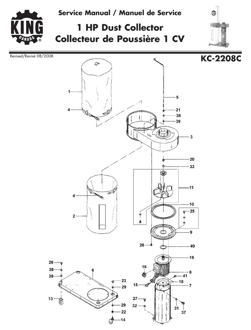
King Canada
King Canada KC-2208C Service manual

King Industrial
King Industrial KC-5043FX instruction manual
Chiko
Chiko CBA-1000AT3-HC-DSA-V1 instruction manual

U.S.SAWS
U.S.SAWS ULTRA VAC 1250-G operating manual
Oneida Air Systems
Oneida Air Systems XXK100300 owner's manual

Oneida Air Systems
Oneida Air Systems Vortex DCS owner's manual
