IGM Laguna Fusion 3 User manual

Producer / Hersteller / Výrobce / Výrobca / Gyártó / Producent:
Laguna Tools Inc
2072 Alton Pkwy
Irvine, CA 92606,
USA
Phone: +1 800-234-1976
Website: www.lagunatools.com
Distributor / Distributor / Distributor / Distribútor / Forgalmazó / Dystrybutor:
IGM nástroje a stroje s.r.o.
Ke Kopanině 560, 252 67, Tuchoměřice, Praha-západ
Česká republika
+420 220 950 910
www.igm.cz
CEF33623003 2019-30
Table Saw
Tischkreissäge
Kotoučová pila
Kotúčová píla
Körfűrészgép
Pilarka tarczowa
Fusion3
man_151-Fusion3_A4ob_kotoucova-pila_EN+DE+CZ+SK+HU+PL_v1.6
EN Operating Instructions
(ofcial Laguna text)
DE Gebrauchsanweisung
(Übersetzung der Originalgebrauchsanweisung)
CZ Návod k obsluze
(překlad původního návodu)
SK Návod na obsluhu
(preklad pôvodného návodu)
HU Használati útmutató
(eredeti használati útmutató fordítása)
PL Instrukcja obsługi
(tłumaczenie oryginalnej instrukcji)

-2-www.igmtools.com
CE-Declaration of Conformity
Product: Table Saw
FUSION3
Type number: CEF33623003
Brand: Laguna
Manufacturer:
Laguna Tools Inc
2072 Alton Pkwy, Irvine, CA 92606, USA
Declare under our sole responsibility that this product is in conformity with the following directives:
- Machinery Directive 2006/42/ES
- Low Voltage Directive 2014/35/ES
- Electromagnetic Compatibility Directive 2014/30/ES
Designed in conformity with:
** EN 1870-19:2013
EN60204-1:2006+AC:2010
Technical documentation processed by:
TUV Rheinland LGA Products GMBH
Certicate number: BM50418591 & BM50418592
2019-09 Ivo Mlej, CEO
IGM nástroje a stroje s.r.o., Ke kopanině 560, 252 67 Tuchoměřice, Česká republika

-3-www.igmtools.com
Contents
1. Declaration of conformity
1.1 Warranty
2. About this manual
3. Fusion 3 Specications
3.1 Contents
3.2 Technical
3.3 Main Features
4. General Safety
4.1 Intended Use
4.2 Work Area
4.3 Personal Safety
4.4 Tool Use
4.5 Guarding Related Warnings
4.6 Work Related Warnings
4.7 Kickback Causes and Related Warnings
4.8 Table Saw Operating Prodedure Warnings
4.9 Electrical
4.10 Noise emissions
4.11 Grounding
4.12 Rulings
4.13 Notice on safe use of the machine
5. Machine overview
5.1 Controls
6. Setup
6.1 Receiving and unpacking
6.2 Inventory
6.3 Loose parts & overview
6.4 General setup
6.5 Installing/removing the throat plate
6.6 Installing/removing safety accessories
6.7 Installing/removing the blade
7. Adjustments
7.1 Fence adjustments
7.2 Table adjustments
7.3 Arbor and tilt adjustments
7.4 Accessory adjustments
7.5 Push block and push stick
8. Type of cut
8.1 Ripping
8.2 Bevel ripping
8.3 Ripping small workpieces
8.4 Cross cutting
8.5 Bevel cross cutting
8.6 Mitre cuts
9. Maintenance
9.1 Internal Components Map
10. Trouble-shooting
1. Declaration of conformity
We declare that this product is in compliance
with the directive and the standard mentioned
on the previous page of this manual.
1.1 Warranty
IGM Tools & Machinery strives to always
deliver high-quality machinery. The warranty is
governed by the valid terms and conditions of
IGM Tools & Machinery available at
www.igmtools.com.
2. About manual
This manual is intended to thoroughly cover the
setup up, maintenance, and proper adjustments
of your new purchase. Aside from the
proceeding general safety considerations,
this manual DOES NOT cover woodworking
or metalworking techniques that are possible
with this product and the appropriate safety
precautions necessary for safe practices. There
are several organizations with published safe
practices, techniques, and proper operation of
this tool. Or look for handy tips and instructions
at www.igmtools.com.
3. Fusion 3 specications
3.1 Contents
Professional Square Zero Clearance Throat
Plate (pre-installed)
250 mm Saw Blade (pre-installed)
Riving Knife (pre-installed)
Mitre Gauge (ships in tool holder)
Tool Holder (pre-installed)
Fence
Blade Guard
Arbor Wrench
Installation and Adjustment Tools
Pic. 1
3.2 Technical Data
Power 230V / 50 Hz / 1 Phase
Motor Type
TEFC Capacitor Start AC Induction
Power Input 2200 W
Motor Speed 2850 /min-1
Full Load Amperage 14.5 A
Start Capacitor 400 µF-U
Run Capacitor 50 µF-U
Switch Type
Magnetic with Overload Protection
Power Transfer Single V-Ribbed 142J FJ
Power Cord 2 m / H07RNF
Power Plug Included CEE 7/7
Breaker Recommendation 16 A,
tripping characteristic C (16/1/C)
General
Footprint (LxW) 503 x 520 mm
Overall Dimensions (LxWxH)
1663 mm x 1652 mm x 1081 mm
Shipping Dimensions (LxWxH)
1130 mm x 1100 mm x 1190 mm
Weight (No Accessories) 157 Kg
Shipping Weight: 202 Kg
Dust Collection: Outlet Dia. 101.6 mm
Dust Collection m3/h, min. 934 m3/h
Sound Emissions N/A
Specics
Blade Diameter 250 mm
Bore Diameter 30 mm
Arbor Speed 3800 /min-1
Blade Rotation Counter-Clockwise
(face arbor)
Rip Capacity, with Fence
914,4 mm Right (1 320,8 mm w/ accessories)
Max. Depth of Cut 90° 79 mm
Max. Depth of Cut 45° 56 mm
Blade Tilt 45° Left, 3° Arbor Adjustment
Table Dim., with Extensions (LxW)
1117 mm x 1663 mm
Wing Dimensions (LxW) 792 x 305 mm
Mitre Slot 19 and 23 mm, T-Slot
Fence Type
Sliding Cam Action Fully Adjustable
Fence Dim (LxWxTh.) 670 x 80 x 17 mm
Throat Plate Type Zero Clearance
Throat Plate (LxWxTh.) 372 x 104.5 x 13 mm
Floor to Table Height 887 mm
Pic. 2
Pic. 3
EN - English
Operating Instructions (Laguna manual)
Dear Woodworker,
Thank you for your purchase and welcome to the Laguna Tools group of discerning woodworkers. We understand that you have a
choice of where to purchase your machines and appreciate the condence you have in the Laguna Tools brand.
Every machine manufactured by Laguna Tools has been carefully designed and well thought through from a woodworker’s perspective.
Through hands-on experience, Laguna Tools is constantly working hard to make innovative, precision products. Products that inspire
you to create works of art, are a joy to run and work on, and encourage your performance.

-4-www.igmtools.com
Pic. 4
3.3 Main Features
• Robust cast-iron trunnion.
• Cast-iron control wheels.
• Two T-slots on the side of the blade.
• Smooth control of the blade height and tilt.
• Lever for a quick blade swap.
• Adjustable control panel.
• Quick clamping riving knife.
• Integrated wheel for simple mobility.
• Includes rear table.
4. General Safety
Warning: Read all safety considerations.
Failure to follow this set of guidelines can result
in unwarranted damage to the machine and
serious injury to the operator and bystanders.
Save all warnings and instructions for future
reference.
4.1 Intended Use
• Table saw and the workpiece guide equipment
supplied with it are intended to be used
exclusively for the following purposes:
- Laminated and non-laminated board materials
(e.g. chipboard, coreboard, MDF board,...)
- Solid wood
- Gypsum plasterboard, Cardboard, Veneer with
a suitable clamping device
- Dimensionally stable plastics (thermoset
plastics, thermoplastics).Sawing these materials
does not normally involve any risks in respect of
dust, chips, and thermal degradation products.
Tools:
• The chosen saw blade must be suitable both
for the specic work cycle and for the specic
material.
• Only circular blades made of tungsten carbide
and have a diameter of 250 mm, arbor size 30
mm are allowed to be used.
• Saw blades made of high-alloy high-speed
steel (HSS) or chrome are not allowed to be
used.
• Saw blades and their xing devices shall
conform to EN 847-1:2013.
Site of installation/use:
• The machine is not suitable for use outdoors,
or in rooms that are subject to moisture or the
risk of explosions.
• The intended use of the machine involves
connection to suitable dust collection.
• The intended ambient temperature used of the
machine: +10 °C to +35 °C.
• The intended altitude used of the machine :
shall be at altitudes up to 1000 m above mean
sea level.
• The intended Relative humidity used of the
machine : not exceed 50% at 35°C.
• Intended use also involves compliance with
our specied operating, maintenance and repair
conditions and the safety information contained
in the operating instructions.
• The table saw may only be used, set up and
maintained by persons who are familiar with the
machine and aware of the dangers.
• The pertinent accident prevention regulations
as well as any other generally recognized
technical safety and industrial medicine rules
must be observed.
• Repair work must be carried out by our own
customer service or by an organization that we
have authorized. Only original spare parts are
allowed to be used for this. we will assume no
warranty for any damage that is caused by using
non-original spare parts.
Warning: The machine is prohibited to be used in
a potentially explosive atmosphere!
4.2 Work Area
• Keep all children and untrained persons away
from the machine. Do not allow bystanders to
touch the machine or power cord. All people but
the operator should be away from the work area.
• Keep work area clean and well lit. A cluttered
area can limit the range of motion needed by the
machine and cause serious injury to the operator
or damage to the machine.
• Make sure the work area is child-proof
and inaccessible to untrained persons. Use
padlocks where possible and keep all machines
unplugged when not in use.
• Do not keep or place tools in outdoor, damp, or
dangerous environments. Never operate the tool
under wet or damp conditions; there is a serious
risk of electrical shock. Exposing this product to
those environments may result in damage to the
tool and operator injury. Do not use tool in the
presence of ammable liquids or gasses.
• Do not operate machine in explosive
atmospheres, such as in the presence of
ammable liquids, gases or dust. Machine create
sparks which may ignite the dust or fumes.
4.3 Personal Safety
• Stay alert, watch what you are doing and use
common sense when operating a power tool. do
not use a power tool while you are tired or under
the inuence of drugs, alcohol or medication.
A moment of inattention while operating power
tools may result in serious personal injury.
• Use personal protective equipment. always
wear eye protection. Protective equipment such
as a dust mask, non-skid safety shoes, hard
hat or hearing protection used for appropriate
conditions will reduce personal injuries.
• Prevent unintentional starting. Ensure the
switch is in the off-position before connecting to
power source and/or battery pack, picking up or
carrying the tool. Carrying power tools with your
nger on the switch or energizing power tools
that have the switch on invites accidents.
• Remove any adjusting key or wrench before
turning the power tool on. A wrench or a key left
attached to a rotating part of the power tool may
result in personal injury.
• Do not overreach. Keep proper footing and
balance at all times. This enables better control
of the power tool in unexpected situations.
• Dress properly. do not wear loose clothing or
jewellery. Keep your hair and clothing away from
moving parts. Loose clothes, jewellery or long
hair can be caught in moving parts.
• If devices are provided for the connection of
dust extraction and collection facilities, ensure
these are connected and properly used. Use of
dust collection can reduce dust-related hazards.
• Do not let familiarity gained from frequent use
of tools allow you to become complacent and
ignore tool safety principles. A careless action
can cause severe injury within a fraction of a
second.
• Know your machine. Read and understand the
owner’s manual and labels afxed to the tool.
Learn its application and limitations as well as
the specic potential hazards peculiar to this
tool.
• Use safety goggles. Some machines require
additional face shielding than offered by safety
goggles alone. Know your machine and the
proper PPE to use.
• Use ear protection. Some machines operate at
very high noise levels. To prevent harm, be sure
to use ear protection always.
• Guard against electric shock. Prevent all bodily
contact with grounded surfaces and parts of the
machine that pose electrical threats.
• Avoid accidental starting for machines without
magnetic or automatic shut-off switches.
Make sure the tool is in the off position prior to
plugging it in.
• Keep guards in place. Machine parts like
riving knifes, blade guard, cutter-head guards,
feather boards, push sticks, etc. are designed
to minimize possible injury. Keep those parts
in place unless a safer means of operation is
available.
• Be alert always and give 100% of your
attention to the operation of this tool. Failure
to do so can result in serious injury to both the
operator and bystanders.
• Do not rely on guards. The operator of this tool
is 100% responsible for his/her own safety. The
guards and safety components sold with this
machine are not enough to ensure safety.
• Check for damaged parts. Before every use
of this tool, makes sure the machine and any
components of the machine are not damaged
or at the risk of being damaged. If a damaged
part is discovered, stop immediately and put the
machine out of service until the part is replaced.
Warning: All repairs should be done by trained
repairmen. Contact your supplier or a competent
repair service.
Warning: Use only supplier Tools or compatible
and marked replacement parts. All others may
cause damage or harm.
Warning: Use only manufacturer-recommended
accessories. Some accessories may cause
damage or harm.
4.4 Tool Use
• Do not force the power tool. use the correct
power tool for your application. The correct
power tool will do the job better and safer at the
rate for which it was designed.
• Do not use the power tool if the switch does not
turn it on and off. Any power tool that cannot be
controlled with the switch is dangerous and must
be repaired.

-5-www.igmtools.com
• Disconnect the plug from the power source
and/or remove the battery pack, if detachable,
from the power tool before making any
adjustments, changing accessories, or storing
power tools. Such preventive safety measures
reduce the risk of starting the power tool
accidentally.
• Store idle power tools out of the reach of
children and do not allow persons unfamiliar
with the power tool or these instructions
to operate the power tool. Power tools are
dangerous in the hands of untrained users.
• Maintain power tools and accessories. check
for misalignment or binding of moving parts,
breakage of parts and any other condition
that may affect the power tool’s operation. If
damaged, have the power tool repaired before
use. Many accidents are caused by poorly
maintained power tools.
• Keep cutting tools sharp and clean.
Properly maintained cutting tools with sharp
cutting edges are less likely to bind and are
easier to control.
• Use the power tool, accessories and tool
bits etc. in accordance with these instructions,
taking into account the working conditions and
the work to be performed. Use of the power
tool for operations different from those intended
could result in a hazardous situation.
• Keep handles and grasping surfaces dry,
clean and free from oil and grease. Slippery
handles and grasping surfaces do not allow
for safe handling and control of the tool in
unexpected situations.
• Use proper speed. A machine will do a better
and safer job when operated at the proper
speed.
• Use the correct tool for the job. Know
the limitations and capabilities of your new
purchase. Do not try to “t a square peg in a
round hole.
• Secure the work piece. For all woodworking
and metalworking applications, the workpiece
should be secured correctly by the operator
using appropriate clamps and vises. Always
use a clamp or vise when available — it is safer
than using your hands.
• Feed direction. If feed rate is applicable, then
there is only one direction of feed rate for the
tool. Do not force the workpiece in the wrong
feed direction.
• Never leave tool running unattended. Do not
leave the tool until it comes to a complete stop.
When unattended, unplug the tool.
• Maintain tools with care. Keep cutting
tools sharp and clean for better and safer
performance.
• Follow instruction for lubricating and changing
accessories. Inspect tool cords periodically
and if damaged have then repaired by an
authorized service facility. Inspect extension
cords periodically and replace if damaged.
Keep hand dry, clean and free from oil and
grease.
• Illumination. Adequate general or localized
lighting shall be provided.
• Dust Collection. During use the saw benches
shall be connected to an external chip and dust
extraction system.
4.5 Guarding related warnings
• Keep guards in place. Guards must be in
working order and be properly mounted.
A guard that is loose, damaged, or is not
functioning correctly must be repaired or
replaced.
• Always use saw blade guard and riving
knife for every through–cutting operation. For
through-cutting operations where the saw blade
cuts completely through the thickness of the
workpiece, the guard and other safety devices
help reduce the risk of injury.
• Make sure the saw blade is not contacting
the guard, riving knife or the workpiece before
the switch is turned on. Inadvertent contact of
these items with the saw blade could cause a
hazardous condition.
• Adjust the riving knife as described in
this instruction manual. Incorrect spacing,
positioning and alignment can make the riving
knife ineffective in reducing the likelihood of
kickback.
• For the riving knife to work, it must be
engaged in the workpiece. The riving knife is
ineffective when cutting workpieces that are
too short to be engaged with the riving knife.
Under these conditions a kickback cannot be
prevented by the riving knife.
• Use the appropriate saw blade for the riving
knife. For the riving knife to function properly,
the saw blade diameter must match the
appropriate riving knife and the body of the saw
blade must be thinner than the thickness of
the riving knife and the cutting width of the saw
blade must be wider than the thickness of the
riving knife.
4.6 Work related warnings
• Danger: never place your ngers or hands
in the vicinity or in line with the saw blade. A
moment of inattention or a slip could direct
your hand towards the saw blade and result in
serious personal injury.
• Feed the workpiece into the saw blade or
cutter only against the direction of rotation.
Feeding the workpiece in the same direction
that the saw blade is rotating above the table
may result in the workpiece, and your hand,
being pulled into the saw blade.
• Never use the mitre gauge to feed the
workpiece when ripping and do not use the rip
fence as a length stop when cross cutting with
the mitre gauge. Guiding the workpiece with the
rip fence and the mitre gauge at the same time
increases the likelihood of saw blade binding
and kickback.
• When ripping, always apply the workpiece
feeding force between the fence and the saw
blade. Use a push stick when the distance
between the fence and the saw blade is less
than 150 mm, and use a push block when this
distance is less than 50 mm. Work helping
devices will keep your hand at a safe distance
from the saw blade.
• Use only the push stick provided by the
manufacturer or constructed in accordance
with the instructions. This push stick provides
sufcient distance of the hand from the saw
blade.
• Never use a damaged or cut push stick. A
damaged push stick may break causing your
hand to slip into the saw blade.
• Do not perform any operation “freehand”.
Always use either the rip fence or the mitre
gauge to position and guide the workpiece.
“Freehand” means using your hands to support
or guide the workpiece, in lieu of a rip fence
or mitre gauge. Freehand sawing leads to
misalignment, binding and kickback.
• Never reach around or over a rotating saw
blade. Reaching for a workpiece may lead to
accidental contact with the moving saw blade.
• Provide auxiliary workpiece support to the
rear and/or sides of the saw table for long and/
or wide workpieces to keep them level. A long
and/or wide workpiece has a tendency to pivot
on the table’s edge, causing loss of control, saw
blade binding and kickback.
• Feed workpiece at an even pace. Do not
bend or twist the workpiece. If jamming occurs,
turn the tool off immediately, unplug the tool
then clear the jam. Jamming the saw blade by
the workpiece can cause kickback or stall the
motor.
• Do not remove pieces of cut-off material while
the saw is running. The material may become
trapped between the fence or inside the saw
blade guard and the saw blade pulling your
ngers into the saw blade. Turn the saw off and
wait until the saw blade stops before removing
material.
• Use an auxiliary fence in contact with the table
top when ripping workpieces less than 2 mm
thick. A thin workpiece may wedge under the rip
fence and create a kickback.
4.7 Kickback causes and related warnings
• Never stand directly in line with the saw blade.
Always position your body on the same side
of the saw blade as the fence. Kickback may
propel the workpiece at high velocity towards
anyone standing in front and in line with the
saw blade.
• Never reach over or in back of the saw blade
to pull or to support the workpiece. Accidental
contact with the saw blade may occur or
kickback may drag your ngers into the saw
blade.
• Never hold and press the workpiece that is
being cut off against the rotating saw blade.
Pressing the workpiece being cut off against the
saw blade will create a binding condition and
kickback.
• Align the fence to be parallel with the saw
blade. A misaligned fence will pinch the
workpiece against the saw blade and create
kickback.
• Use extra caution when making a cut into
blind areas of assembled workpieces. The
protruding saw blade may cut objects that can
cause kickback. Note, the above safety warning
only applies to tools where such cuts are
permitted by design and instruction.
• Support large panels to minimise the risk of
saw blade pinching and kickback. Large panels
tend to sag under their own weight. Support(s)
must be placed under all portions of the panel
overhanging the table top.
• Use extra caution when cutting a workpiece
that is twisted, knotted, warped or does not
have a straight edge to guide it with a mitre
gauge or along the fence. A warped, knotted,
or twisted workpiece is unstable and causes
misalignment of the kerf with the saw blade,
binding and kickback.
• Never cut more than one workpiece, stacked
vertically or horizontally. The saw blade could
pick up one or more pieces and cause kickback.
• When restarting the saw with the saw blade
in the workpiece, centre the saw blade in the
kerf so that the saw teeth are not engaged in
the material. If the saw blade binds, it may lift

-6-www.igmtools.com
up the workpiece and cause kickback when the
saw is restarted.
• Keep saw blades clean, sharp, and with
sufcient set. Never use warped saw blades or
saw blades with cracked or broken teeth. Sharp
and properly set saw blades minimise binding,
stalling and kickback.
4.8 Table saw operating procedure warnings
• Turn off the table saw and disconnect the
power cord when removing the table insert,
changing the saw blade or making adjustments
to the riving knife or saw blade guard,
and when the machine is left unattended.
Precautionary measures will avoid accidents.
• Never leave the table saw running
unattended. Turn it off and don’t leave the
tool until it comes to a complete stop. An
unattended running saw is an uncontrolled
hazard.
• Locate the table saw in a well-lit and level
area where you can maintain good footing and
balance. It should be installed in an area that
provides enough room to easily handle the size
of your workpiece. Cramped, dark areas, and
uneven slippery oors invite accidents.
• Frequently clean and remove sawdust from
under the saw table and/or the dust collection
device. Accumulated sawdust is combustible
and may self-ignite.
• The table saw must be secured. A table saw
that is not properly secured may move or tip
over.
• Remove tools, wood scraps, etc. From
the table before the table saw is turned
on. Distraction or a potential jam can be
dangerous.
• Always use saw blades with correct size and
shape (diamond versus round) of arbour holes.
Saw blades that do not match the mounting
hardware of the saw will run off-centre, causing
loss of control.
• Never use damaged or incorrect saw blade
mounting means such as anges, saw blade
washers, bolts or nuts. These mounting means
were specially designed for your saw, for safe
operation and optimum performance.
• Never stand on the table saw, do not use
it as a stepping stool. Serious injury could
occur if the tool is tipped or if the cutting tool is
accidentally contacted.
• Make sure that the saw blade is installed
to rotate in the proper direction. Do not use
grinding wheels, wire brushes, or abrasive
wheels on a table saw. Improper saw
blade installation or use of accessories not
recommended may cause serious injury.
4.9 Electrical
• Machine plugs must match the outlet. Never
modify the plug in any way. Do not use any
adapter plugs with earthed (grounded) power
tools. Unmodied plugs and matching outlets
will reduce risk of electric shock.
• Disconnect the power rst. Always disconnect
machine from power supply before adjusting,
changing tooling, or servicing machine.
• Power supply: 230V/50Hz/1 phase.
• Use a qualied electrician for all electrical
connections. Failure to do so may result in
damage to the tool and electrical shock to the
operator and bystanders.
• Power plugs. Your machine may not come
with a power plug because of the variance
in power receptacles. Consult with a local
electrician prior to purchasing a power plug.
Do not abuse the cord. Never use the cord for
carrying, pulling or unplugging the power tool.
Keep cord away from heat, oil, sharp edges
or moving parts. Damaged or entangled cords
increase the risk of electric shock.
• Extension cords. Consult with or use a
qualied electrician prior to sizing extension
cords for use with this machine.
• When operating a power tool outdoors, use an
extension cord suitable for outdoor use. Use of
a cord suitable for outdoor use reduces the risk
of electric shock.
• If operating a power tool in a damp location is
unavoidable, use a residual current device (rcd)
protected supply.
• Electrical protection. End user should connect
the machine to a circuit protected with a 16 A
circuit breaker, tripping characteristic C (16/1/C)
and overvoltage protection.
4.10 Noise emissions
• Reference standards.
The measurements of noise emission were
conducted according to the EN ISO 11202:2010
for the determination of sound pressure level
at the operation positions. When the measured
sound pressure levels at the operation positions
exceed 80db(a), the measurements of sound
power levels were conducted according to EN
ISO 3746:2010.
• Operating conditions.
The operating conditions for noise
measurement comply with Annex A of ISO
7960:1995.
• Testing results:
A-weighted Sound Pressure - Level 91.3 dB
A-weighted Sound Power - Level 113.8 dB
Associated uncertainty - K=4dB
Background noise of measurement surrounding
is - 55dB
The gures quoted are emission levels and
are not necessarily safe working levels. Whilst
there is a correlation between the emission
and exposure levels, this cannot be used
reliably to determine whether or not further
precautions are required. Factors that inuence
the actual level of exposure of the workforce
include the characteristics of the work room, the
other sources of noise etc. i.e. the number of
machines and other adjacent processes. Also
the permissible exposure level can vary from
country to country. This information, however,
will enable the user of the machine to make a
better evaluation of the hazard and risk.
4.11 Grounding
• Proper grounding of your machines lowers the
risk of injury by electricity.
• Avoid body contact with earthed or grounded
surfaces, such as pipes, radiators, ranges
and refrigerators. There is an increased risk
of electric shock if your body is earthed or
grounded.
• Do not modify the plug. Do not remove any of
the prongs attached to the proper plug for the
machine.
• Use only 3-wire extension cords.
Some extension cords only have two wires,
which does not allow for grounding.
• Always use grounded connections and work
only on a grounded circuit.
4.12 Rulings
Warning: Before connecting this tool to a
power supply (receptacle, outlet, etc.) Make
sure that the voltage supplied is the same
that is specied on the nameplate of the tool.
Also make sure that the power supply is
equipped with the appropriate breaker and
plug according to your local electrical code. If
in doubt, do not plug in the machine. Using this
tool with a voltage different than that stated
on the nameplate can damage the electrical
components of this machine and any such
damage will not be covered by a warranty.
Warning: Some dust created by power sanding,
sawing, grinding, drilling and other construction
activities contains chemicals known to cause
cancer, birth defects or other reproductive harm.
Some examples of these chemicals are:
• Lead from lead-based paint.
• Crystalline silica from bricks, cement, and
other masonry products.
• Arsenic and chromium from chemically treated
lumber.
Your risk of exposure varies, depending on how
often you do this type of work. To reduce your
exposure to these chemicals, work in a well-
ventilated area and work with approved safety
equipment, such as face or dust masks that are
specically designed to lter out microscopic
particles.
4.13 Notice on safe use
The machinery sold by Laguna Tools,
distributed by IGM Tools and machinery co.,
are safe when used properly and comply to
with the CE norms, standards and regulations
for safe use. Laguna Tools or IGM is in no
way responsible for injury or death that occurs
while using this product. Your personal safety is
100% your responsibility and using this product
requires 100% of your attention.
If there is any concern related to the application
you are intending to use this tool for, DO NOT
proceed until you have contacted the retailer
you purchased it from and have been advised
on the correct application of the product.
This manual is intended to thoroughly cover
the setup up, maintenance, and proper
adjustments of your new purchase. Aside from
the proceeding general safety considerations,
this manual DOES NOT cover woodworking
or metalworking techniques that are possible
with this product and the appropriate safety
precautions necessary for safe practices. There
are several organizations with published safe
practices, techniques, and proper operation of
this tool.
Warning
The symbols below advise that you
follow the correct safety procedures when using
this machine.
Keep your ngers away from the
saw blade
Environmental protection:
Waste electrical products should not
be disposed of with household waste.
Please recycle where facilities exist.
Check with your local Authority or retailer for
recycling advice.

-7-www.igmtools.com
5.1 Controls
Start/Stop/Fuse
Pic. 6
1. Magnetic switch
2. Overload protector
3. Fuse
CAUTION: Always turn off and unplug the
machine before changing the fuse.
Arbor height control
Pic. 7
The arbor height control adjusts the height of
the blade. Centred in the control is the height
adjustment lock. Behind the control is the tile
gauge. CW to raise, CCW to lower blade.
CAUTION: DO NOT ADJUST HEIGHT WHEEL
WHEN LOCKED.
Arbor tilt control
Pic. 8
The tilt control, located on the right of the
cabinet, adjusts the tilt of the arbor. Centre is
Dusk mask should be worn.
Eye protection should be worn.
Ear protection should be worn.
Disconnect from power supply before
servicing
Fully read manual and safety
instructions before use.
Safety gloves should be worn.
5. Machine Overview
1. Start / Stop
2. Rip Fence
3. Fence Front guide
4. Fence Rear guide
5. Table with mitre slots
6. Cabinet with integrated mobility kit
7. Arbor height adjustment control
8. Arbor tilt adjustment control
9. Dust extraction outlet
10. Moror cover
11. Throat plate
12. Blade
13. Blade guard
14. Riving knife
15. Arbor wrench
16. Push stick
17. Mitre gauge
the tilt lock. CW to tilt left, CCW to tilt the blade
to the right.
CAUTION: DO NOT ADJUST TILT WHEEL
WHEN LOCKED.
Fence clamp lock
Pic. 9
The fence clamp securely locks the fence
anywhere on the rail by a cam action
mechanism.
6. Setup
Use Caution: Your new Laguna Tools machine
is heavy. Use a minimum of two people when
lifting the tool into position and moving the tool
into position.
Warning: DO NOT connect to a power supply
until the setup is complete. DO NOT perform
any of the following steps, installations, or
adjustments with the saw connected to the
power source.
Warning: To avoid set-up problems, to prevent
potential damage to the machine and personal
injury, read through the entire setup section
prior to setting up the machine.
6.1 Receiving and unpacking
If any damage has occurred because of
shipment, note the damage on the bill of lading
or refuse the shipment. Immediately call the
dealer store where the machine was purchased.
TRANSPORTATION AND STORAGE. The
measures of anti-rust and shockproof should
be taken during packing. The machine endures
transportation and store in -25~55°C ambient
temperature.
Be careful not to expose the machine to rain or
damage when transporting or storing.
While transporting or handling the machine,
be careful and let the activity be done by
qualied personnel especially trained for
this kind of activity!
While the machine is being loaded or
unloaded, make sure that no person or
subject gets pressed by the machine!
Select proper transportation device
according to the weight of the machine.
Make sure the lifting capacity of
transportation device is competent for the
weight of the machine.
TRANSPORTATION BEFORE UNPACKING
As standard, the machine is packed in a robust
wooden box. Pic.10 shows the tool that can be
used to transport the packaging.
Pic. 10
UNPACKING
1. Receive your table saw.
2. Unscrew the crate fasteners.
3. Lift crate off pallet.
4. Check Inventory.
5. Wipe off protective oils.
Pic. 5

-8-www.igmtools.com
Receiving your tablesaw
Pic. 11
This is how machine is shipped from the
factory.
Unscrew the crate fasteners
Pic. 12
Use a drill with a #2 Phillips head bit and
remove the bottom screws from carton. These
screws may be discarded.
Lift crate off pallet
Pic. 13
Use two persons to lift the carton away from the
pallet. There should be three packages along
with the table saw.
NOTE: The throat plate, riving knife, and 10”
blade is pre-installed in the machine. The miter
gauge, and blade changing tool are positioned
in the tool holder located on the right side of the
cabinet.
Check Inventory
Pic. 14
1. Fence, install tools, push stick, blade guard
assembly
2. Smaller fence rail sections, hardware kit
3. Longer fence rail sections.
Wipe off protective plastics
Pic. 15
Peel back the protective vinyl plastic and wipe
away the oil with a waste rag.
Use Caution: An oily rag can be a serious re
hazard. Discard in an appropriate manner.
Tech Tip: To help keep your table top clean and
to prevent or clean any rust, we recommend
waxing your tabletop with an appropriate wax
rubbing compound. This will also reduce friction
under operation. Rust can be removed with
WD-40.
6.2 Inventory
Box 1
Fence: PTSF236110175-0130-1-1
Push stick: PTSF236110175-0130-130
Blade guard: PTSF236110175-01302-1
Install Tools
Fence hooks*: PTSF236110175-0130-118
* Fence storage hooks may be pre-installed.
Box 2
Rear Rail 2: PTSF236110175-0130-127.5
Front Rail 2: PTSF236110175-0130-127.6
Hardware kit
Box 3
Rear rail 1: PTSF236110175-0130-127.5
Front rail 1: PTSF236110175-0130-127.6
Pre-installed on machine
Throat plate PTSF236110175-0130-6
Riving knife PTSF236110175-0130-27
250mm blade PTSF236110175-0130-33
Mitre gauge PTSF236110175-0130-3
Arbor wrench PTSF236110175-0130-137
Tool storage PTSF236110175-0130-120
Wings (2x) PTSF236110175-0130-4
Note: The front rail part number is comprised of
two pieces – both long and short. The rear rail
part number is comprised of two pieces – long
and short.
Note.: For safety reasons, this machine is not
sold with a tape-rule for the left side of the
blade. It is not a missing part.
6.3 Loose Parts & Overview
Your new machine has been mostly assembled
at the certied ISO 91001 factory where it was
made. Some parts must be assembled by the
purchaser. Please read all steps rst before
proceeding with step one.
Pic. 16
Blade Guard
Pic. 17
5) M8x1.5+ lock washer + washer + nut
Pic. 18
(5) Square head 8x1.5 + washer + nut
Pic. 19
Fence hooks (step 2)
Pic. 20
Pic. 21
6.4 General Setup
1. Attach the short rear fence support
2. Attach the long rear fence support
3. Level the rear rails and fasten
4. Attach T-Slot bolts to front table
5. Insert long front rail fence support
6. Insert short front rail and switch
7. Join front fence supports
8. Align the entire front rail to blade mark
9. Level and fasten the front rail
10. Insert fence
11. Level the saw by adjusting casters
1. Attach short rear fence support
Use the supplied wrench and Alan key to
loosely fasten (2) bolts, lock washers, washers,

-9-www.igmtools.com
and nuts to the short rear fence guide and
the back left of the table. STOP BEFORE
TIGHTENING: Keep bolts loose until entire rail
assembly is in place to properly level rail.
Pic. 22
2. Attach short rear fence support
Repeat step 1 for the longer rear fence section
with (3) bolts, lock washers, washers, and nuts.
Use the same assembly diagram in Step 1.
NOTICE: If the fence hooks are not yet
installed, now is a good time to do so.
Pic. 23
3. Attach short rear fence support
To level the rear fence with the table top,
place a rigid straight edge on top of the rails.
Apply downward force at both arrow indicators
and simultaneously tighten the bolts with the
supplied Allen key and wrench.
Pic. 24
4. Attach T-slot bolts to front table
Loosely fasten the (5) square headed bolts, (5)
washers, and (5) nuts. A couple revolutions of
the bolt will be tight enough. Prepare to insert
the (2) aluminium front rail sections.
Pic. 25
5.Insert the long front fence support
Insert the long Front Rail. STOP BEFORE
TIGHTENING: Keep these bolts loose until the
entire rail assembly is in place to properly level
the rail.
Pic. 26
6. Insert short rail and switch
Insert the short front rail into the rst square
head bolt. IMPORTANT: Insert the switch
assembly before joining the two front rail
pieces. STOP BEFORE TIGHTENING.
Pic. 27
7. Join front fence supports
Align the pins and join the two front rail pieces
and rmly push together.
Pic. 28
8. Align the front rail with blade
Using the blade notching on the measuring
tape, align the entire front rail section to the
blade.
Pic. 29
9. Level and fasten front rail
To level the front rail sections to the table top,
use a ridged straight edge atop the loosely
t rail sections. Apply downward force to the
straight edge while keeping the two sections
rmly together. Simultaneously fasten down the
bolts.
Pic. 30
10. Install the fence
Install the fence by placing the front end
rst. Be sure that the handle is in the open,
unlocked, position prior to installing.
Pic. 31
11. Level the table saw with casters and x
Level the table saw with the ground and x the
machine on the oor with screws.
Pic. 32
6.5 Installing/removing the throat plate
1. Unplug the table saw!
2. Insert the throat plate back end rst.
3. Lower the throat plate to the table.
4. Lock the throat plate with the thumb-lock.
5. Level the throat plate with the table using
the cat screws.
Note: This machine is shipped with a zero-
clearance throat plate that has already been
cut at the factory. Because of this, there may be
some residue already in the saw.
Installing the throat plate
Pic. 33
WARNING: MAKE SURE SAW IS
UNPLUGGED. To remove or install the throat
plate, rst set it to the unlock position. Then,
insert the rear end rst and tilt the other end
down into position.
Levelling the throat plate
Pic. 34
To level the throat plate, adjust the leveling
screws.
Note: Make sure the throat plate is lower than
the cast iron table. Having the throat plate
higher at any position can interfere with the
workpiece feed and cause injury or harm and
increase the chance of kickback
6.6 Installing/removing safety accessories
A: Saw blade
B: Riving knife housing
C: Cam action lever
D: Riving knife
E: Blade guard
F: Blade compliant markings

-10-www.igmtools.com
Pic. 35
• Note on the Riving Knife
Pic. 36
Since Riving Knife, other than those offered by
Laguna, has not been tested with this product,
use of such accessories with this tool could be
hazardous. To reduce the risk of injury, only
Laguna, recommended accessories should be
used with this product.
• Note on the saw blade
Pic. 37
Installing/removing the riving knife
1. Unplug the tablesaw!
2. Make sure the lock is in open position
3. Insert the blade guard
4. Position the guard insert
5. Lock the blade guard
6. Reinstall throat plate
CAUTION: Make sure the blade guard is in line
with the blade. If it is not in line, please see the
Adjustment section.
3. Insert the blade guard
Pic. 38
WARNING: MAKE SURE SAW IS
UNPLUGGED.
With the throat plate removed, and the cam lock
mechanism in the open position (pulled up),
insert the blade guard insert into the slot.
4. Position to the left of the casing
Pic. 39
Make sure the guard is positioned correctly and
seated in the bottom of the casing. Grasp the
pawls with one hand, leaving the other hand
free to activate the cam action lock.
5. Lock the blade guard
Pic. 40
Keep rm hold of the blade guard with left hand
and engage the cam lock with the thumb of
your right hand.
6. Reinstall the throat plate
Pic. 41
Grasp the pawls up and out of the way to re-
insert the throat plate. Lock the throat plate.
Pic. 42
CAUTION: Make sure the riving knife is in-line
with the blade. If it is not in line, please see the
Adjustments Section.
6.7 Installing/removing the Blade
1. Unplug the table saw!
2. Remove any blade guards, riving knifes, and
the throat plate to access the blade.
3. Set the arbor tilt to 0 degrees and lock.
4. Raise saw to highest position.
5. Engage blade lock (red component).
6. Remove the arbor nut and ange with arbor
wrench.
7. Remove or install blade.
CAUTION: Make sure the teeth of the blade are
facing the front of the saw as shown.
2. Remove all accessories
Pic. 43
WARNING: MAKE SURE SAW IS
UNPLUGGED. To access the blade remove all
accessories around the blade, including riving
knifes, throat plates, ect.
3. Set arbor tilt to 0 and lock.
Pic. 44
Set the arbor tilt to 0 degrees and lock the arbor
to prevent it from moving when installing or
removing blades.
Limit position of the top guard
Use riving knife only with 250 mm
diameter blade
Riving knife thickness 2,3 mm
Only use this riving knife with 2 mm
and 3 mm teeth thickness
No saw blade should be used where
the maximum marked speed is lower
than the selected rotational speed of
the saw spindle.
5500 max rpm

-11-www.igmtools.com
4. Raise saw blade to highest position
Pic. 45
5. Engage the blade lock
Pic. 46
6. Remove arbor nut and ange
Pic. 47
7. Adjustments
Your Laguna Tools machine comes fully
adjusted from the factory, but it is good practice
to double check these adjustments and make
sure the tool is in safe operating condition.
7.1 Fence Adjustments
Fitting the fence:
You will need to t the fence to the right side of
the blade to use the table saw. You will need to
t the fence to the right side of the blade to use
the table saw.
1. Unplug the table saw!
2. Hold fence with both hands, with cam lock up.
3. Place fence in fence guide
4. Check cam lock action, adjust if necessary.
2. Place fence in fence guide
Pic. 48
While holding the fence and the cam lock, raise
the cam lock to engage the open position.
Insert the fence frame into the front rail.
3. Check Cam lock action
Pic. 49
The fence can slide freely in any position to the
right of the blade. If the fence does not lock,
adjust both blade paralleling set screws.
Adjusting the Scale (rule):
The scale will need to be “zeroed” every
time the fence guide is taken off the table
or adjusted. The fence must be zeroed for
accurate cuts when using the scale.
1. Unplug the table saw!
2. Position the fence up to blade.
3. Loosen the transparent viewport.
4. Adjust the view as needed.
5. Tighten the view screws.
Place fence in fence guide
Pic. 50
WARNING: MAKE SURE SAW IS
UNPLUGGED. With the blade in a high
position, bring the fence close to — but not
touching — the blade. Use a folded piece of
paper between the blade and the fence to
ensure good distance.
Adjust the Viewport
Pic. 51
Use a #2 Philips head driver to loosen (but
do not remove) the transparent scale reader.
Adjust the viewport as needed, tighten the
screws. Note: If adjusting the viewport does not
allow enough to zero the scale, see step 8 of
general setup.
Adjusting the Fence Glide Bushings:
You may need to adjust the height of the
bushings on either side or rear of the fence. The
fence should be between 1-3 mm off the table
to prevent scratches.
1. Unplug the table saw!
2. Unlock the fence.
3. Use a hex key to adjust the front bushing
height.
4. Use a wrench to adjust the rear bushing
height.
Front Bushings
Pic. 52
To adjust the front bushings, use the included
hex key to raise or lower the nylon bushings
that make contact with the front fence rail.
Rear Bushings
Pic. 53
Adjusting the Fence to be parallel with the
Blade: It is very important to only operated this
saw with the blade parallel to the fence. Note: If
this section does not help, please see the table
adjustments section: Adjusting the Table to be
Parallel with the Blade. The blade needs to be
parallel to the table (mitre slots) to effectively
make the fence parallel to the blade.
1. Unplug the table saw!
2. Position the fence to access the fence
adjustment screws.
3. Use a hex key to adjust each side
4. Make small increments and check
Use caution: It is not guaranteed that the fence
will be parallel to the saw blade when shipped
from factory. Make sure to make all required
adjustments to make the fence parallel to the
saw blade prior to operation.
Position fence to access adj. screws
Pic. 54
WARNING: MAKE SURE SAW IS
UNPLUGGED. Take the fence out of position
and ip it on its back side to access the cat
screws that push the nylon supports in/out.

-12-www.igmtools.com
Use a hex key to adjust
Pic. 55
Use the included hex key to adjust the depth of
each nylon support. Do small increments and
check.
7.2 Table Adjustments
Adjusting the Table to be Parallel with the
Blade: It is good practice to make sure that the
table is always parallel to the blade by checking
it often. You can do this with a combination
square or with a dial indicator on an appropriate
mount. Check the IGM website for these tools.
Good
Pic. 56
Combination Square. Notice: This method may
leave scratched.
Better
Pic. 57
A dial indicator on a mitre gauge.
Best
Pic. 58
A dedicated saw dial indicator. Such as this one
by ‘Iagging’.
1. Un-plug the tablesaw!
2. Take initial measurement.
Pic. 59
WARNING: MAKE SURE SAW IS
UNPLUGGED. With the throat plate and all
attachments removed, raise the blade to the
highest position at 90 degrees with the table.
Take an initial measurement about 1 cm from
the ground edge of the blade as shown.
3. Take relative measurement
Pic. 60
Keep the mitre gauge against the left rail
and slowly move crossed the blade. Take
the second measurement and compare with
the initial measurement. Adjust the table to
compensate false measurements. There are 3
bolts to loosen prior to adjusting the table, see
step 4.
4. Loosen the three table fastener bolts.
5. Adjust as needed.
Loosen Table Bolts
Pic. 61
Locate and loosen right side table to cabinet
bolt (above the tool holder).
Loosen Table Bolts
Pic. 62
Locate and loosen left side table to cabinet bolt
(above the motor cover).
Loosen Table Bolts
Pic. 63
Locate and adjust the rear table to cabinet bolt.
Adjusting or Installing Extension Wings: (may
be pre-installed):
To install or remove the extension wings, an
advised method is provided. This method
makes it easy to make the extension wings at
with the table but requires the use of two ridged
supports and four clamps.
1. Unplug the table saw!
2. Clamp supports to table.
3. Place extension wing on supports.
4. Join or adjust the wing with supplied bolts.
Note: The clamps may scratch the tabletop!
Use a cloth or soft wood between
the clamp and the iron surfaces.
2. Take initial measurement
Pic. 64
WARNING: MAKE SURE SAW IS
UNPLUGGED. Clamp two wooden supports
to the underside of the table saw as shown.
Straight 2x4 lumber will work
3. Take relative measurement
Pic. 65
Place the extension wing on the supports and
place into position.
4. Join or adjust wing
Pic. 66
You will need (4) m10 bolts and (4) washers to
fasten each extension wing to the table top. Be
sure to align the extension wing to the table top
prior to tightening the bolts.

-13-www.igmtools.com
7.3 Arbor and Tilt Adjustments
Adjusting the Blade Tilt Limits
You can check the arbor (blade) tilt limits with
an angle nder or 45-degree triangle. If these
limits are not within 0 degrees and 45 degrees,
use the following steps to adjust.
1. Unplug the table saw!
2. Remove the motor cover.
3. Remove the tool storage cover.
4. Locate tilt adjustment screws.
5. Adjust as needed.
6. Adjust the scale and indicator as needed.
Use caution: From the factory, the tilt limits
are pre-set to 0 and 45 degrees tilt to the left.
Adjusting this limit will slightly alter that amount
which may cause throat plate or fence to
interfere. Adjusting these limits should only be
done to set the tilt limits to 0 and 45 degrees.
2. Remove motor cover
Pic. 67
WARNING: MAKE SURE SAW IS
UNPLUGGED.
To access the left side tilt limit adjustment
screw, remove the motor housing cover using
a #2 Philips head driver. There are 4 screws in
total holding on the motor cover..
3. Remove tool storage cover
Pic. 68
To access the right-side tilt adjustment screw,
remove the tool storage using a #2 Philips head
driver. There are 4 screws in total holding on
the tool storage box.
4. Locate Tilt Adjustment
Pic. 69
Locate the tilt adjustment screw. Screw it in to
expand the tilt range slightly.
5. Adjust as needed
Pic. 70
Locate the tilt adjustment screw. Screw it in to
expand the tilt range slightly.
6. Adjust scale (if needed)
Pic. 71
Adjust the scale and tilt indicator on the cabinet
if needed.
Adjusting the Belt:
It is good practice to check the tension of the
belt often to ensure that the saw is performing
properly. If the table saw blade is slipping or is
feeling underpowered, you may need to tighten
the belt. To do so, follow the steps below.
1. Unplug the table saw!
2. Remove the motor cover.
3. Locate belt adjustment bolt.
4. Tighten or loosen with weight of motor.
Use Caution: DO NOT OVERTIGHTEN BELT!
The weight of the motor is adequate to put
enough tension on the belt. Only tight enough
to prevent slippage.
Remove the motor cover
Pic. 72
WARNING: MAKE SURE SAW IS
UNPLUGGED.
To access the motor, remove the motor housing
cover using a #2 Philips head driver. There are
4 screws in total holding on the motor cover.
Locating Belt Adjustment bolt
Pic. 73
To adjust the belt, set blade to 0° on tilt scale,
then raise or lower blade to approximately 2“
above table. Loosen the belt adjustment bolt.
With the bolt loose, Raise or lower the motor so
that the belt is tight.
Changing the belt:
1. Unplug the table saw!
2. Remove all throatplates, blades, and blade
accessories.
3. Remove the motor cover.
4. Remove the dust shroud.
5. Loosen the Belt adjustment bolt and loosen
belt by raising motor.
6. Remove belt. NOTE: you may need to lower
the arbor height to access the belt.
7. Replace belt.
Use Caution: DO NOT OVERTIGHTEN BELT!
The weight of the motor is adequate to put
enough tension on the belt. Only tight enough
to prevent slippage.
Belt Adjustment bolt
Pic. 74
WARNING: MAKE SURE SAW IS
UNPLUGGED. NOTICE: The drawing shown
is with the top of the table removed. AVOID
removing the table top. The belt can easily be
changed without removing the table top.
Accessing the Belt
Pic. 75
7.4 Accessory Adjustments
Insert Block Adjustments (For all Safety
Accessories):
The Riving knife, blade guard, or splitter must
be aligned with the blade to be used affectively.
The riving knife should only be used with
-14-www.igmtools.com
blades specied on the riving knife. To adjust
the position of the blade safety attachments,
relative to the saw blade: NOTE: if the cam
action lever does not lock or is too hard to lock
– adjust the nut on the back side of the cam
action axil. You will need to remove the motor
cover.
Pic. 76
Loosen the two middle setting bolts. These
two bolts fasten the assembly in-between the
set screws and the arbor block.
Pic. 77
Adjust the set screws as needed to correct
an out of align blade attachment. Do small
adjustments and check.
Pic. 78
As Adjustments are made, the blade
attachments will translate, not rotate, by design.
This ensures that the workpiece will not get
held up. CHECK COMPONENTS BEFORE
EVERY CUT.
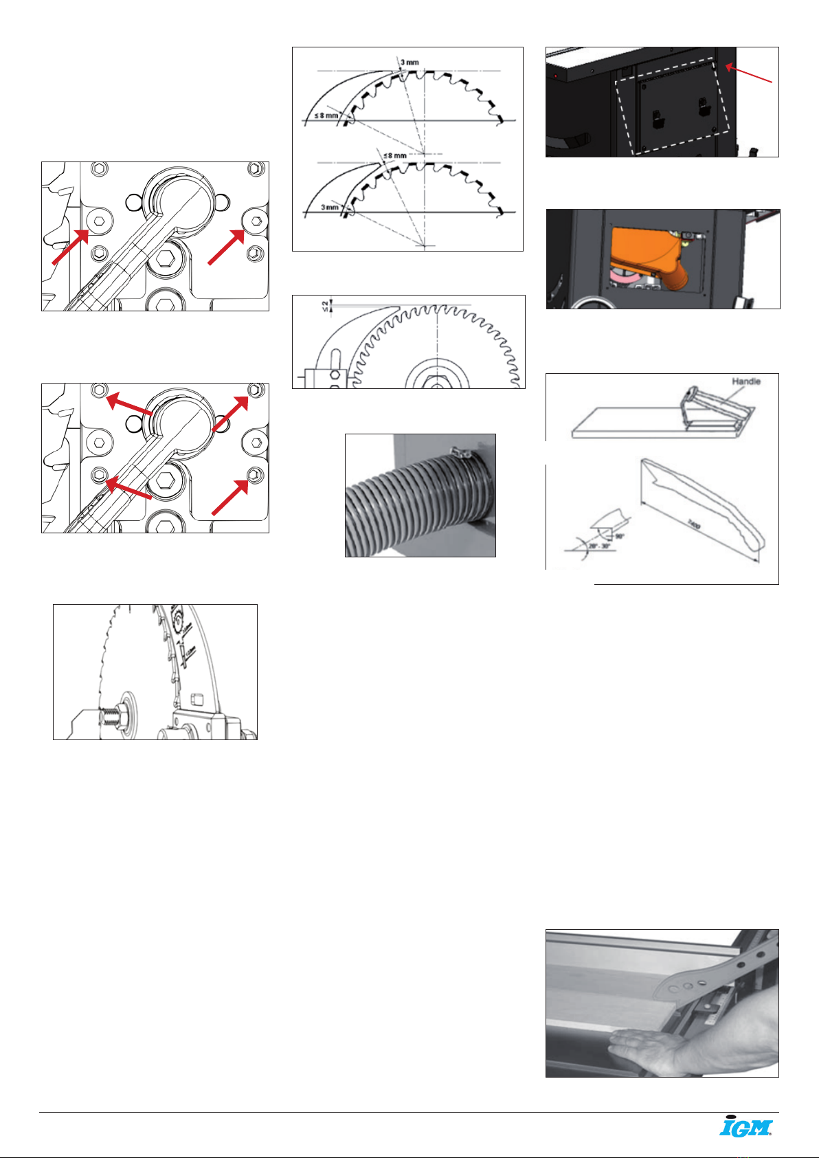
Riving Knife Adjustments::
After changing a saw blade, always check that
the riving knife is correctly set!
The distance of the riving knife from the gear
rim must be between 3 mm and 8 mm.
The highest point of the riving knife must be set
at least 2mm beneath the topmost tooth.
The riving knife must be at least 0.2 mm thicker
than the main saw blade.
Check that the saw blade clamping system is
tight before operating the machine!
Pic. 79
Pic. 80
Dust Collector:
Pic. 81
There is a 100 mm dust outlet located on
the lower left of the saw cabinet allowing for
the connection to a dust collection system
(not included). Air current speed is 20m/s for
vacuum suction dust emission index. When
air current speed of dust collector device (in
accordance with EN 12779:2004+ A1:2009) is
not lower than 20m/s, ensure machine can be
normal exhausted. User must wear dustproof
mask.
1. Fit the 100 mm dust hose over the dust port,
(not included) and secure in place with a hose
clamp.
2. Make sure the hose could not come off.
3. Required air ow: 934 m3/h
4. Ensure pressure drop of each dust collector
outlet carrying air current speed: 1500Pa
5. Wind speed of dust collector tube m/s: dry
chips: 20m/s, water content is equal to18% wet
chips: 28m/s.
Warning: Always turn on the dust collector
before starting the saw and stop the saw before
turning off the dust collector.
Note.: A tight t is necessary for proper
performance.
Warning: Always turn off the table saw before
removing any cover of the machine.
Pic. 82
Remove the side cover, to clean and remove
dust, debris from dust hood.
Pic. 83
7.5 Push block and push stick
A push block (Pic.2) and A push stick (Pic.3)
must be used.
If the workpiece is less then 12 0mm, you must
use the push stick to prevent your hands from
getting too close to the saw blade.
Push block must be used to cut narrow
workpieces and, when necessary, to push the
workpiece against the fence, a push block can
be easily made by the operator as Pic.2.
Warning: Use only the push stick provided by
the manufacturer or constructed in accordance
with the instructions. This push stick provides
sufcient distance of the hand from the saw
blade.
Warning: Never use a damaged or cut push
stick. A damaged push stick may break causing
your hand to slip into the saw blade.
8. Type of Cut
Warning: Always wear safety glasses, a
respirator and hearing protection when
operating this machine.
Note: This saw is only designed to cut wood.
8.1 Ripping
Pic. 86
Pic. 84
Pic. 85

-15-www.igmtools.com
Cutting a wood plank or sheet of plywood
lengthwise to reduce its width is called “ripping”.
To rip stock, hold the work with both hands
pushing it into the blade as well as rmly
against the rip fence so that it is cut straight.
• Never rip or cut wood without using the fence
or mitre gauge to guide it because the stock
could kickback.
• Always use the blade guard and riving knife
assembly when cutting wood. The riving knife
prevents the saw “kerf” (the slit cut by the
blade) from closing and binding the blade,
which can overload and/or stall the motor or
cause the blade to lift and eject the workpiece
towards the front of the saw at very high
speeds. The blade guard keeps your ngers
away from the blade and also reduces the
amount of sawdust ying free.
• Some jobs may require removing the riving
knife along with the cover. Do not forget to put
them back when you are done.
As you complete the rip, the wood will either
remain on the table, tilt up to be caught on
the end of the guard, or fall onto the oor (or
outfeed table). The waste part of the stock
remains on the table to be removed only after
the saw is stopped (unless it is large enough for
immediate safe removal).
If the work to be ripped is narrow, it is safer
to use a push stick, rather than the hands, to
feed it into the blade Push sticks with non-slip
grippers can be purchased, but a shop-made
one works just as well. When ripping extremely
narrow stock that may not clear the width of
the blade guard, or very thin material such
as panelling, which may slip between the
underside of the fence and the table surface,
a strip of wood as an auxiliary guide can be
attached to the fence.
WARNING: Keep the blade guard installed and
in the down position. Failure to do this could
result in serious personal injury or death.
WARNING: Never reach in towards the blade
while the blade is still spinning! whenever a rip
cut is completed, turn off the saw and wait for
the blade to come to a complete stop before
reaching in to remove the workpiece or the
waste material.
8.2 Bevel Ripping
Pic. 87
Bevel ripping is performed the same as ripping
but with the saw blade set to an angle not
perpendicular with the table surface. To tilt the
blade to the left, anywhere between 0° and 45°.
This is used most often when cutting bevels,
compound mitres or chamfers.
After changing the bevel angle verify the
alignment of the guard and splitter; make sure
there is clearance with the saw blade.
8.3 Ripping small workpieces
Do not attempt rip cuts if the work piece is too
small, as this will oblige you to place your hands
too close to the blade and put you at serious
risk of injury. When ripping narrower widths; use
a push block or a push stick in order to avoid
placing hands near the blade.
8.4 Cross cutting
Cutting against the grain, to shorten the length
of a board is crosscutting. With some smaller
sized and rectangular pieces, you often have
the choice of ripping or crosscutting. Always
use the mitre gauge, when crosscutting; never
cut a piece unsupported. The mitre gauge may
be used in either slot, but most operators prefer
the left groove for typical work. When the blade
is tilted for bevel cutting, use the table slot that
does not cause interference with your hand or
the saw blade guard.
To begin crosscutting, place the work on the
mitre gauge and, with the motor OFF, slide it up
close to the blade to align the outer edges of
the teeth with your cut mark (see pic).
Keep a rm grip as you pull the mitre gauge
and the wood back away from the blade. Lower
the blade guard, turn on the saw and make the
cut. When the work is cut through, move one or
both cut pieces.
Pic. 88
Warning: When cross-cutting round stock it
is necessary to secure the workpiece against
rotation by using a suitable jig.
8.5 Bevel cross cutting
This procedure is the same as cross cutting
except that the blade is set to an angle other
than 0. After changing the bevel angle, verify
the alignment of the guard and splitter and
verify that there is clearance with the saw blade.
Pic. 89
8.6 Mitre cuts
This operation is the same as cross cutting,
except the mitre gauge is set to an angle. Hold
the work piece rmly against the mitre gauge
and feed the workpiece slowly into the blade to
prevent it from moving during the cut.
Pic. 90
9. Maintenance
To keep you Laguna Tools machine in top
performance for many years please follow
this maintenance schedule and refer to any
instructions.
Daily Check:
• Loose mounting bolts
• Damaged saw blade
• Damaged riving knifes, splitters, or blade
guards
• Worn or damaged wires
• Any other unsafe condition
Weekly Maintenance:
• Clean table surface and mitre slot grooves
• Clean and protect cast-iron table
• Clean rip fence
Monthly Maintenance:
• Clean/vacuum dust buildup from inside
cabinet and off motors.
• Check/replace belt for proper tension, damage
or wear.
Every 6–12 Months:
• Lubricate trunnion slides.
• Lubricate worm gear.
• Lubricate leadscrew.
• Lubricate gearing and gearboxes.

-16-www.igmtools.com
9.1 Internal Components Map
A. Motor
B. Dust Shroud
C. Trunnion Slides (Support)
D. Upper Trunnion
E. Lower Trunnion
10. Trouble-Shooting
Machine will not start or continues to trip the breaker.
Possible Causes
1. Start capacitor at fault.
2. Motor connection wired wrong.
3. Wiring at fault.
4. Motor Start/Stop switch at fault.
5. Motor at fault.
6. Run capacitor at fault.
7. Wall circuit breaker tripped or at fault.
8. Power supply switched OFF or at fault.
9. Plug/receptacle at fault or wired incorrectly.
Possible Solution
1. Test/replace if faulty.
2. Correct motor wiring connections.
3. Check/x broken, disconnected, or corroded wires.
4. Replace switch.
5. Test/repair/replace.
6. Test/replace if faulty.
7. Ensure circuit size is correct/replace weak breaker.
8. Ensure power supply is on/has correct voltage.
9. Test wires and contacts; correct the wiring.
Machine is excessively loud or is experiencing excessive vibration.
Possible Causes
1. Motor or component loose
2. Blade at fault
3. Motor mount loose/broken
4. Machine incorrectly mounted
5. Arbor pulley loose
6. Belts worn or loose
7. Pulley loose or at fault
8. Arbor bearings at fault
9. Motor bearings at fault
Possible Solution
1. Inspect/replace damaged bolts/nuts, and re-tighten with thread-locking
uid.
2. Replace warped/bent blade; re-sharpen dull blade.
3. Tighten/replace.
4. Tighten mounting bolts; relocate/shim machine.
5. Retighten/replace arbor pulley.
6. Adjust tension of/replace belt
7. Realign/replace shaft, pulley, setscrew, and key.
8. Replace arbor housing bearings; replace arbor.
9. Test by rotating shaft; grinding/loose shaft requires bearing
replacement.
Machine trips the overload, or feels underpowered during operation.
Possible Causes
1. Feed rate/cutting speed too fast
2. Workpiece material unsuitable for machine
3. Pulley/sprocket slipping on shaft
4. Motor bearings at fault
5. Contactor at fault
6. Motor overheated
7. Workpiece crooked; fence not aligned
8. Machine undersized for task; wrong blade
9. Run capacitor at fault
10. Belt is slipping from pulley
11. Motor wired incorrectly
12. Plug/receptacle at fault
13. Motor at fault
Possible Solution
1. Decrease feed rate/cutting speed.
2. Only cut wood; ensure moisture is below 20%.
3. Replace loose pulley/shaft.
4. Test/repair/replace.
5. Test for good contacts/correct wiring.
6. Clean motor, let cool, and reduce workload.
7. Straighten or replace workpiece; adjust fence.
8. Use correct blade; reduce feed rate or depth of cut.
9. Test all legs for power/replace if faulty.
10. Adjust tension of/replace belt.
11. Test/repair/replace.
12. Wire motor correctly.
13. Test/repair/replace.
WARNING:
1. Wiring should only be done by professional electricians. Always make sure the machine is properly earthed.
2. All wirings in the cabinets should be protected against direct contact to at least IP2X when nishing electrical installation.
3. All exposed conductive parts should be connected to the protective bonding circuit.
4. Close and lock the door of cabinets.
WARNING:
1. Enough space around the machine and the cabinets should be kept in order to maintain conveniently.
2. The machine should be installed in a workshop with good illumination and ventilation.
3. Over-voltage protection device should be provided by end user on spot.
F. Arbor Nut
G. Arbor Washer (Flange)
H. Blade
I. Tilt Gearing
J. Height Gearing
K. Belt (behind blade)
L. Worm Screw
M. Tilt Plate
N. Start Capacitor (see spec sheet)
O. Run Capacitor (see spec sheet)
FG
H
B
E
C
N
A
K
D
C
J
I
M
O

-17-www.igmtools.com
CE-Konformitätserklärung
Produkt: Tischkreissäge
FUSION3
Typnummer: CEF33623003
Marke: Laguna
Hersteller:
Laguna Tools Inc
2072 Alton Pkwy, Irvine, CA 92606, USA
Hiermit erklären wir in unserer alleinigen Verantwortung, dass dieses Produkt den folgenden Richtlinien entspricht:
- Machinery Directive 2006/42/EC
- Low voltage Directive 2014/35/EC
- Electromagnetic Compatibility Directive 2014/30/EC
Entworfen in Übereinstimmung mit:
** EN 1870-19:2013
EN60204-1:2006+AC:2010
Technische Dokumentation erstellt von:
TUV Rheinland LGA Products GMBH
Číslo certikátu: 50100405 002
2019-09 Ivo Mlej, CEO
IGM nástroje a stroje s.r.o., Ke kopanině 560, 252 67 Tuchoměřice, Česká republika

-18-www.igmtools.com
Inhaltsverzeichnis
1. Konformitätserklärung
1.1 Gewährleistung
2. Über die
Gebrauchsanweisung
3. Spezikation der Maschine
3.1 Bestandteile der Maschine
3.2 Technische Daten
3.3 Hauptbestandteile
4. Allgemeine Arbeitssicherheit
4.1 Bestimmungsgemäße Verwendung
4.2 Arbeitsbereich
4.3 Persönliche Sicherheit
4.4 Einsatz der Werkzeuge
4.5 Hinweise zu Sicherheitseinrichtungen
4.6 Hinweise zu Maschinenteilen
4.7 Rückstoßursachen und damit verbundene
Gefahren
4.8 Warnungen zur Bedienung der Maschine
4.9 Elektroschaltung
4.10 Lärm
4.11 Erdung
4.12 Regelungen
4.13 Hinweis zur sicheren Verwendung der
Maschine
5. Allgemeine Beschreibung der
Maschine
5.1 Bedienelemente
6. Zusammenbau der Maschine
6.1 Übernahme und Auspackung
6.2 Kisteninhalt
6.3 Lose Teile und Übersicht
6.4 Zusammenbau der Maschine
6.5 Einbau/Entnahme der Tischeinlage
6.6 Einbau/Entnahme der
Sicherheitseinrichtungen
6.7 Einbau/Entnahme des Sägeblatts
7. Maschineneinstellungen
7.1 Einstellung des Sägeanschlags
7.2 Tischeinstellung
7.3 Einstellung der Wellenneigung
7.4 Einstellung der Wellenneigung
7.5 Einstellung der Zubehörteile
7.6 Schiebestock und Schiebeblock
8. Schnitttypen
8.1 Längsschnitt
8.2 Winkellängsschnitt
8.3 Längsschneiden schmaler Werkstücke
8.4 Querschnitt
8.5 Winkelquerschnitt
8.6 Gehrungsschnitt
9. Instandhaltung
Verzeichnis der Bestandteile
10. Störungsbehebung
1. Konformitätserklärung
Wir erklären, dass dieses Produkt im Einklang
mit der auf der vorherigen Seite dieser
Gebrauchsanweisung genannten Richtlinie und
Norm.
1.1 Gewährleistung
Die IGM nástroje a stroje s.r.o. strebt
danach, stets ein hochwertiges und
leistungsfähiges Produkt zu liefern. Die
Inanspruchnahme der Gewährleistung richtet
sich nach den jeweils geltenden Geschäfts- und
Gewährleistungsbedingungen der IGM nástroje
a stroje s.r.o.
2. Über die Gebrauchsanweisung
Der Zweck dieses Handbuchs ist es,
die Einstellungen, Instandhaltung und
Anpassungen Ihrer neuen Maschine zu decken.
Neben allgemeinen Sicherheitshinweisen
gilt dieses Handbuch NICHT für Holz- oder
Metallbearbeitungstechniken und für die
relevanten Sicherheitsvorkehrungen, die
für eine sichere Bedienung erforderlich
sind. Es gibt mehrere Organisationen mit
Veröffentlichungen zur sicheren Handhabung,
zu Techniken und zur ordnungsgemäßen
Verwendung dieser Maschine.
3. Spezikation der Maschine
3.1 Bestandteile der Maschine
Pro-Tischeinlage (in der Tischkreissäge
eingebaut)
250 mm Sägeblatt (in der Tischkreissäge
eingebaut)
Spaltkeil (in der Tischkreissäge eingebaut)
Winkelanschlag (auf Seite der Tischkreissäge)
Zubehörhalter (in der Tischkreissäge eingebaut)
Längsanschlag Sägeblattabdeckung
Mutterschlüssel
Montageschlüssel
Abb. 1
3.2 Technische Daten
Spannversorgung 230V / 50Hz / 1 Phase
Motortyp
Asynchroner AC Motor mit TEFC Kondensator
Aufnahmeleistung 2200 W
Drehzahl 2850 U/min-1
Strom bei max. Belastung 14,5 A
Anlaufkondensator 400 gF
Betriebskondensator
Schaltertyp
Magnetschalter mit Überlastungsschutz
Energieübertragung Keilriemen 142J FJ
Netzkabel 2 m / H07RNF
Stecker (Gabel) CEE 7/7
Empfohlener Leistungsschutzschalter
16, Abschaltcharakteristik C (16/1/C)
Allgemein
Spur der Maschine (LxB) 503 x 520 mm
Abmessung (LxBxH)
1663 mm x 1652 mm x 1081 mm
Transportabmessung (LxBxH)
1130 mm x 1100 mm x 1190 mm
Gewicht (ohne Zubehör) 157 kg
Transportgewicht: 202 kg
Absaugung: Absaugstutzen Durchmesser
101,6 mm
Absaugung m3/Std., min. 934 m3/Std.
Geräuschemissionen N/A
Spezikation der Tischkreissäge
Sägeblattdurchmesser 250 mm
Sägeblattbefestigung Durchmesser 30 mm
Drehzahl 3800 /min-1 Sägeblattrotation
Im Uhrzeigersinn (in Richtung zur Spannung)
Längsschnitt, mit Anschlag
914,4 mm rechts (1,320 mm mit
Zubehör) Max. Schnitthöhe bei 90° 79 mm
Max. Schnitthöhe bei 45° 56 mm
Sägeblattneigung
45° nach links 3° Dorneinrichtung Abmessung
der Tischkreissäge, mit Erweiterung (LxBxDi)
1117,5 mm x 1663 mm Abmessung der
Seitentische (LxB) 792 x 305 mm Nutenführung
für Winkelanschlag
19 und 23 mm, T-Nutenführung
Typ des Längsanschlags
Einstellbarer Anschlag mit Exzenter
Anschlagabmessung (LxBxDi.)
670 x 80 x 17 mm
Typ der Tischeinlage Pro-Tischeinlage
Abmessung der Tischeinlage (LxBxDi.)
372 x 104.5 x 13 mm Arbeitshöhe
(Boden - Tisch) 887 mm
Abb. 2
DE - Deutsch
Gebrauchsanweisung (Übersetzung der Originalgebrauchsanweisung)
Sehr geehrter Kunde,
Vielen Dank für Ihren Kauf und willkommen in der Familie der Besitzer der Laguna Tools Maschinen von IGM. Wir sind uns dessen
bewusst, dass Sie derzeit auf dem Markt unzählige Marken von Holzbearbeitungsmaschinen nden und wir schätzen es, dass Sie sich
gerade für die Maschine der Laguna Tools von IGM entschieden haben.
Jede Laguna Tools Maschine wurde sorgfältig entworfen, um den Bedürfnissen des Kunden entgegenzukommen. Dank praktischer
Erfahrung arbeitet Laguna Tools ständig daran, innovative Präzisionsprodukte zu schaffen.
Produkte, die Sie zur Schaffung von Kunstwerken inspirieren, Freude an Arbeit bieten und Ihre Leistung unterstützen.

-19-www.igmtools.com
Abb. 3
Abb. 4
3.3 Hauptbestandteile
• Robuste Gussmotoraufhängung.
• Gussbedienräder.
• Zwei T-Nutenführungen auf beiden Seiten des
Sägeblatts.
• Leichtgängige und benutzerfreundliche
Sägeblatthöhen- und Winkelverstellung.
• Hebel für schnellen Sägeblattwechsel.
• Positionierbarer Hauptschalter.
• Schnelle Befestigung des Spaltkeils.
• Integrierte verschließbare Räder.
• Hinterer Zusatztisch im Lieferumfang
4. Allgemeine Arbeitssicherheit
Warnung: Lesen Sie alle Sicherheitshinweise.
Die Nichtbeachtung der Sicherheitshinweise
kann zu Schäden an der Maschine und zu
schweren Verletzungen des Bedieners und
der Umstehenden führen. Bewahren Sie alle
Warnungen und Anweisungen zum späteren
Nachschlagen auf.
4.1 Bestimmungsgemäße Verwendung
• Die Tischkreissäge und die Anschläge sind
ausschließlich für folgende Verwendung
bestimmt:
- Laminierte und unlaminierte Werkstoffe (z.B.:
Holspanplatten, MDF, Tischlerplatten usw.)
- Massivholz
- Gipsplatten, Furnierplatten mit geeigneter
Spannvorrichtung
- Formstabile Kunststoffplatten (Durplast,
Thermoplast). Beim Bearbeiten dieser
Werkstoffe entstehen in der Regel keine
Risiken bezüglich Staub, Späne und
thermischer Abbauprodukte. Werkzeuge:
• Das gewählte Kreissägeblatt muss sowohl für
den jeweilige Verwendungszweck als auch der
jeweilige Werkstoff geeignet sein.
• Für die Tischkreissäge sind ausschließlich
Mikro-Korn-Hartmetall-Sägeblätter mit
Sägeblattdurchmesser von bis zu 250 mm,
Bohrungsdurchmesser bis zu 30 mm geeignet.
• Kreissägeblätter aus Schnellarbeitsstahl
oder Chrom-Vanad Sägeblätter dürfen in der
Tischkreissäge nicht verwendet werden.
• Die Kreissägeblätter sowie deren
Spannvorrichtung müssen der EN 847-1: 2013
entsprechen. Aufstellungs- / Verwendungsort:
Die Maschine ist nicht für den Betrieb im Freien,
in Feucht- oder explosionsgefährdeten Räumen
geeignet.
• Die Maschine muss mit geeignetem
Absaugsystem betrieben werden.
• Geeignete Umgebungstemperatur: + 10 °C bis
+ 35 °C.
• Geeignete Meereshöhe: bis zu 1000 m über
dem Meeresspiegel.
• Feuchtigkeit: 50 % bei 35 °C nicht
überschreiten.
• Die bestimmungsgemäße Verwendung
umfasst auch die Einhaltung unserer
spezizierten Betriebs-, Instandhaltungs- und
Instandsetzungsbedingungen sowie der
in der Gebrauchsanweisung enthaltenen
Sicherheitshinweise.
• Die Tischkreissäge darf nur von Personen
verwendet, zusammengebaut und
instandgehalten werden, die mit der Maschine
vertraut sind und sich der Gefahren bewusst
sind.
• Relevante Unfallverhütungsvorschriften und
andere allgemein anerkannte Regeln der
technischen Sicherheit sind zu beachten.
• Reparaturen müssen durch zugelassene
Person durchgeführt werden. Es ist erlaubt,
ausschließlich Originalersatzteile zu
verwenden. Wir übernehmen keine Haftung für
Schäden, die durch die Verwendung von nicht
originalen Ersatzteilen verursacht werden.
Warnung: Es ist verboten, die Maschine
in explosionsgefährdeten Bereichen zu
verwenden.
4.2 Arbeitsbereich
• Bewahren Sie die Maschine außerhalb der
Reichweite von Kindern und Personen auf,
die nicht mit der Maschine arbeiten können.
Lassen Sie nicht zu, dass umstehende
Personen die Maschine oder das Netzkabel
berühren. Im Arbeitsbereich sollen sich nur die
Maschinenbediener benden.
• Halten Sie den Arbeitsbereich sauber und gut
beleuchtet. Nicht aufgeräumter Arbeitsbereich
kann den Gebrauch der Maschine einschränken
und Verletzungen verursachen.
• Vergewissern Sie sich, dass der
Arbeitsbereich sicher und für ungeschulte
Personen und Kinder nicht zugänglich ist.
Wenn möglich, sperren Sie die Maschinen
und Arbeitsbereiche ab und lassen Sie alle
Maschinen von der Netzspannung getrennt.
• Bewahren oder platzieren Sie die Maschine
nicht im Freien, in feuchten oder gefährlichen
Räumen. Betreiben Sie die Maschine niemals
unter nassen oder feuchten Bedingungen;
es besteht die ernsthafte Gefahr eines
Stromschlags. Aussetzung der Maschine
diesen Bedingungen kann zu Schäden an der
Maschine sowie zu Verletzungen des Bedieners
führen. Verwenden Sie die Maschine nicht in
Gegenwart von brennbaren Flüssigkeiten oder
Gasen.
• Verwenden Sie die Maschine nicht in
Gegenwart von brennbaren Flüssigkeiten oder
Gasen. Die Maschine erzeugt Funken, die
Staub oder Dämpfe entzünden können.
4.3 Persönliche Sicherheit
• Seien Sie vorsichtig, beobachten Sie,
was Sie tun, und verwenden Sie den
gesunden Menschenverstand, wenn Sie mit
Elektrowerkzeugen arbeiten. Verwenden Sie
Elektrowerkzeuge oder die Maschine nicht,
wenn Sie müde sind und unter dem Einuss
von Drogen, Alkohol oder Medikamenten
stehen. Ein Moment der Unaufmerksamkeit
beim Bedienen von Elektrowerkzeugen kann zu
schweren Verletzungen führen.
• Tragen Sie Schutzkleidung. Tragen
Sie Schutzbrille. Schutzausrüstung wie
Staubmaske, rutschfeste Sicherheitsschuhe,
Helm oder Gehörschutz verringert die
Verletzungsgefahr bei Verwendung, soweit
sie unter geeigneten Bedingungen verwendet
werden.
• Vermeiden Sie unbeabsichtigten Start der
Maschine. Vergewissern Sie sich vor dem
Anschluss an Stromversorgung, dass der
Schalter nicht auf on (Ein) steht.
• Entfernen Sie alle Schraubenschlüssel oder
Werkzeuge von der Oberäche der Maschine,
bevor Sie sie einschalten. Wenn Sie beim
Einschalten Werkzeuge oder Zubehör an der
Maschine lassen, kann dies zu Verletzungen
führen.
• Beugen Sie sich nicht über die Maschine.
Achten Sie bei der Arbeit stets auf das richtige
Gleichgewicht und beugen Sie Ihren Körper
nicht über die Maschine. In unerwarteten
Situationen werden Sie dann mehr Kontrolle
über die Maschine haben.
• Tragen Sie geeignete Kleidung. Tragen Sie
keine lose Kleidung oder Schmuck. Halten Sie
Ihre Haare und Kleidung außer der beweglichen
Teile. Lose Kleidung, Schmuck oder lange
Haare können an beweglichen Teilen hängen
bleiben.
• Wenn Sie die Maschine an Absaug- oder
ähnliche Systeme anschließen können,
überprüfen Sie den ordnungsmäßigen
Anschluss an diese Systeme. Durch die
Verwendung der Absaugung werden die mit
Staub in der Werkstatt verbundenen Risiken
verringert.
• Auch wenn Sie gewöhnt sind, mit
der Maschine zu arbeiten, seien Sie
wachsam. Unachtsame Verwendung kann
in Sekundenbruchteilen zu schweren
Verletzungen führen.
• Das Wichtigste ist, eigene Maschine
zu kennen. Lesen und verstehen Sie die
Gebrauchsanweisung und die Schilder an der
Maschine. Machen Sie sich vertraut mit der
Verwendung, Beschränkungen und Gefahren,
die sich aus der Verwendung der Maschine
ergeben können.
• Tragen Sie Schutzbrille. Verwendung
einiger Maschinen erfordert zusätzlichen
Gesichtsschutz, nicht nur eine Schutzbrille.
Machen Sie sich mit der richtigen Verwendung
von Schutzkleidung vertraut.

-20-www.igmtools.com
• Tragen Sie Gehörschutz. Einige Maschinen
arbeiten mit hohen Geräuschpegeln. Tragen
Sie immer einen Gehörschutz, um Schäden zu
vermeiden.
• Schützen Sie sich vor Stromverletzungen.
Vermeiden Sie jeglichen physischen
Kontakt mit geerdeten Oberächen und
Maschinenteilen, die eine elektrische Gefahr
darstellen.
• Vermeiden Sie versehentliches Starten von
Maschinen. Stellen Sie vor dem Anschließen an
die Stromversorgung sicher, dass der Schalter
auf „Aus“ steht.
• Entfernen Sie nicht die
Sicherheitseinrichtungen. Maschinenteile wie
Spaltkeil, Sägeblattabdeckung, Druckkämme,
Schiebestöcke usw. benden sich an der
Maschine, um das Verletzungsrisiko zu
minimieren. Lassen Sie diese Teile an Ort und
Stelle, wenn Sie kein sichereres Zubehör zur
Verfügung haben.
Seien Sie stets vorsichtig und widmen Sie der
Maschine 100 % Ihrer Aufmerksamkeit. Das
Nichtbeachten kann zu schweren Verletzungen
des Bedieners der Maschine oder umstehender
Personen führen.
• Verlassen Sie sich nicht auf die
Sicherheitseinrichtungen. Die Bediener
dieser Maschine sind zu 100% für eigene
Sicherheit verantwortlich. Die mit dieser
Maschine geleiferten Sicherheits- und
Schutzeinrichtungen genügen nicht, um
Sicherheit zu gewährleisten.
• Überprüfen Sie regelmäßig die Maschinenteile
auf deren Zustand und Beschädigung. Vor
jedem Gebrauch
vergewissern Sie sich, dass weder die
Maschine noch deren Teile beschädigt sind und
dass es auch kein Risiko von Beschädigung
der Maschine oder deren Teile gibt. Wenn Sie
Schäden an der Maschine oder an einem Teil
feststellen, stellen Sie die Arbeit sofort ein und
schalten Sie die Maschine aus, bis das Teil
ausgetauscht ist.
Warnung: Alle Reparaturen sollen durch ein
geschultes Personal durchgeführt werden.
Warnung: Verwenden Sie bei Reparaturen
ausschließlich Laguna Tools Originalteile von
IGM. Andere Teile können Beschädigung der
Maschine oder einen Unfall verursachen.
Warnung: Verwenden Sie ausschließlich
empfohlenes Zubehör. Anderes Zubehör kann
Beschädigung der Maschine oder einen Unfall
verursachen.
4.4 Verwendung der Maschine
• Verwenden Sie Elektrowerkzeuge nicht mit
Gewalt. Verwenden Sie geeignete Werkzeuge
und Maschine für die beabsichtigte Leistung.
Mit der richtigen Maschine oder Werkzeugen
werden Sie die Arbeit besser und sicherer
ausführen.
• Wenn der Schalter nicht funktioniert,
verwenden Sie die Maschine nicht. Jedes
Elektrowerkzeug, dass sich mittels eines
Schalters nicht bedienen lässt, ist gefährlich
und muss repariert werden.
• Bevor Sie jegliche Einstellungen vornehmen,
Zubehör austauschen oder aufbewahren,
ziehen Sie den Stecker aus der Steckdose
aus und/oder entfernen Sie die Batterie,
wenn sie abgezogen werden kann. Solche
Vorbeugungssicherheitsmaßnahmen verringen
das Risiko eines versehentlichen Starts.
• Bewahren Sie die Maschinen außerhalb der
Reichweite von Kindern auf und lassen Sie
Personen, die mit der Maschine oder diesen
Anweisungen nicht vertraut sind, sie nicht
bedienen. Die Maschine ist in Händen von
unqualizierten Benutzern gefährlich.
• Halten Sie die Maschinen und Zubehör
instand. Überprüfen Sie, ob die beweglichen
Teile korrekt ausgerichtet oder verankert und
nicht beschädigt sind. Bei Beschädigung
lassen Sie die Maschine vor der weiteren
Verwendung reparieren. Viele Unfälle werden
durch unkorrekte Instandhaltung der Maschine
verursacht.
• Halten Sie Schneidwerkzeuge scharf und
sauber. Bei ordnungsgemäßer Instandhaltung
sind präzisionskantige Werkzeuge weniger
störanfällig und einfach zu bedienen.
Verwenden Sie die Maschine und ihr
Zubehör gemäß diesen Anweisungen unter
Berücksichtigung der Arbeitsbedingungen
und der auszuführenden Arbeit. Andere als
bestimmungsgemäße Verwendung kann zu
Unfällen oder Beschädigung der Maschine
führen.
• Halten Sie die Griffe der Maschine sauber,
trocken, ohne Öl und Fett. Rutschige Griffe
und Greifächen verhindern die sichere
Handhabung und Bedienung der Maschine in
unerwarteten Situationen.
• Halten Sie die empfohlene Geschwindigkeit
der Maschine ein. Die Maschine führt bessere
und sicherere Arbeiten aus, wenn sie mit der
richtigen Geschwindigkeit betrieben wird.
• Verwenden sie beim Arbeiten richtige
Werkzeuge. Machen Sie sich mit den
Möglichkeiten und Beschränkungen der
Maschine vertraut. Einfach gesagt, versuchen
Sie nicht „ein eckiges Werkstück durch ein
rundes Loch durchzustecken“.
• Sichern Sie das Werkstück richtig ab. Bei
allen Holz- und Metallarbeiten sollte das
Werkstück vom Bediener mit geeigneten
Klemmen und Schraubstöcken ordnungsgemäß
gesichert werden. Verwenden Sie eine Klemme
oder einen Schraubstock, soweit verfügbar.
Deren Verwendung ist sicherer, als wenn das
Werkstück mit Hand gehalten wird.
• Bei dieser Maschine gibt es nur eine richtige
Vorschubrichtung. Drücken Sie das Werkstück
nicht in der falschen Vorschubrichtung.
• Lassen Sie die Maschine niemals
unbeaufsichtigt laufen. Lassen Sie laufende
Maschine nicht allein, bis sie vollständig zum
Stillstand gekommen ist. Wenn die Anlage
unbeaufsichtigt ist, schalten Sie sie von der
Stromversorgung ab.
• Führen Sie Wartung regelmäßig durch. Zur
Gewährleistung einer sauberen und sicheren
Arbeit verwenden Sie nur scharfe und saubere
Werkzeuge.
• Halten Sie Anweisungen für Schmieren
und Zubehörwartung ein. Überprüfen Sie
regelmäßig Kabel der Maschine und wenn sie
beschädigt sind, lassen Sie sie reparieren.
Überprüfen Sie regelmäßig Verlängerungskabel
und tauschen sie Sie aus bei Beschädigung.
Halten Sie beim Arbeiten Ihre Hände sauber
ohne Öl oder Fett.
• Beleuchtung. Sorgen Sie für entsprechende
Beleuchtung der Werkstatt und der Maschine.
• Absaugung. Beim Gebrauch ist die Maschine
ans Absaugsystem zur Abführung von Spänen
und Staub anzuschließen.
4.5 Hinweise zu Sicherheitseinrichtungen
• Entfernen Sie nicht die
Sicherheitseinrichtungen. Die Abdeckungen
müssen in einem betriebsfähigen Zustand
und ordnungsmäßig montiert sein. Eine
Schutzabdeckung, die locker oder beschädigt
ist oder nicht richtig funktioniert, muss repariert
oder ausgetauscht werden.
• Verwenden Sie stets eine
Kreissägeblattabdeckung und einen
Spaltkeil für jedes Schneiden. Die
Sicherheitseinrichtungen verringen das Risiko
eines Unfalls oder Beschädigung der Maschine
beim Schneiden mit der Säge.
• Bevor Sie die Maschine einschalten,
vergewissern Sie sich, dass weder der Spaltkeil
noch die Sägeblattabdeckung das Sägeblatt
berühren. Kontakt dieser Teile bei laufender
Maschine kann zu Gefahren führen.
• Stellen Sie den Spaltkeil gemäß Anweisungen
in dieser Gebrauchsanweisung ein. Unkorrekte
Abstände, Platzierung oder Ausrichtung können
zur Unwirksamkeit des Spaltkeils führen.
• Der Spaltkeil muss das Werkstück berühren,
um richtig funktionieren zu können. Der
Spaltkeil garantiert keinen Rückstoßschutz,
wenn zu kleine Stücke mit der Säge geschnitten
werden, die diesen nicht erreichen. In diesem
Fall kann der Spaltkeil einen Rückstoß
keineswegs verhindern.
• Verwenden Sie das entsprechende
Sägeblatt mit dem Spaltkeil. Damit der
Spaltkeil ordnungsgemäß funktioniert, muss
der Durchmesser des Sägeblattes mit dem
jeweiligen Spaltkeil übereinstimmen; der Körper
des Sägeblattes muss dünner sein als die
Dicke des Spaltkeils und die Schnittbreite des
Sägeblattes muss breiter sein als die Dicke des
Spaltkeils.
4.6 Hinweise zu Maschinenteilen
• Gefahr: Bringen Sie Ihre Finger niemals in
die Nähe des Sägeblatts. Ein Moment der
Unaufmerksamkeit oder ein Ausrutschen kann
zu schweren Verletzungen führen.
• Setzen Sie Werkstücke nur gegen die
Drehrichtung in den Schnitt ein. Wenn Sie das
Werkstück in die gleiche Richtung schneiden,
in der sich das Sägeblatt über dem Tisch dreht,
können das Werkstück und Ihre Hand in den
Schnitt gezogen werden.
• Verwenden Sie niemals den Winkelanschlag
zum Werkstückvorschub beim Längsschneiden.
Beim Querschneiden mit dem Winkelanschlag
verwenden Sie den Längsanschlag nicht
als Materialanschlag. Der Vorschub
des Werkstücks mit dem Längs- und
Winkelanschlag auf einmal erhöht die
Wahrscheinlichkeit des Klemmens oder eines
Rückstoßes.
• Verschieben Sie das Werkstück beim
Längsschneiden hinter den Teil zwischen
dem Längsanschlag und dem Kreissägeblatt.
Soweit der Abstand zwischen dem Sägeblatt
und dem Längsanschlag länger als 150 mm
Table of contents
Languages:
Other IGM Saw manuals


