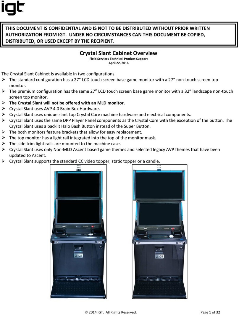
IGT Cobalt 27 User manual

Cobalt™ 27
Service Manual
90-200028-01
Georgia
Cobalt™
March 2020
Technology Training & Support Services
10 Memorial Boulevard, Providence, RI 02903 USA

Cobalt™ 27 Service Manual
SOFTWARE AND HARDWARE FEATURES MENTIONED IN THESE MATERIALS MAY NOT BE AVAILABLE IN
YOUR JURISDICTION, BUT ARE MENTIONED FOR TRAINING PURPOSES ONLY.
Warranty
Information in this document is subject to change without notice and does not represent a commitment on the part of IGT, a
wholly owned subsidiary of IGT. No part of this manual may be reproduced or transmitted in any form or by any means,
electronic or mechanical, including photocopying and recording, for any purpose other than the purchaser's personal use
without written permission of IGT.
Nothing contained in this document shall be construed as a warranty. The warranty, if any, for a product shall be contained
in the contract with IGT for the purchase, lease or license of the product. ALL OTHER WARRANTIES, EXPRESS OR
IMPLIED, INCLUDING BUT NOT LIMITED TO WARRANTIES OF MERCHANTABILITY, FITNESS FOR A
PARTICULAR PURPOSE OR NON-INFRINGEMENT, ARE HEREBY DISCLAIMED. IN NO EVENT SHALL IGT BE
LIABLE FOR DIRECT, INDIRECT, INCIDENTAL, PUNITIVE OR CONSEQUENTIAL DAMAGES, INCLUDING BUT
NOT LIMITED TO LOSS OF USE, REVENUE OR PROFITS.
Hardware Warning!
The following servicing instructions and/or information is for use by QUALIFIED PERSONNEL ONLY.
Systems Trademark and Copyright Information
© 2020 IGT. All rights reserved.
Each and every use of an IGT trademark contained herein is intended to be protected and all rights are reserved.
Third-Party Trademarks
All other trademarks and registered trademarks are the property of their respective owners, without intent to infringe.
Hardware Trademark and Copyright Information
© 2020 IGT. All rights reserved.
Certain trademarks and/or service marks used herein are the property of their respective third party owners. The use of
such marks herein is for identification purposes only, and does not imply an endorsement by IGT of the mark owner, or
vice-versa, or that such mark owner has authorized IGT to promote its products and/or services.
Contact Information
IGT
10 Memorial Boulevard
Providence, Rhode Island 02903
1-401-392-1000
IGT Support
1-866-777-8448
We Appreciate Your Ideas!
Was this material effective? Was it structured in a way that worked for you? Do you have ideas for making it
better?
Help the IGT team hit the jackpot. Please send your feedback to Support@igt.com Give it to us straight – We
appreciate your input.
2 Cobalt™ 27

Table of Contents
Safety 7
Chapter 1 Cobalt Overview 9
Cobalt Features 10
Specifications 11
Environmental Specifications 11
Electrical Specifications 11
Physical Specifications 11
Dimensions 12
Dimensions - with Topper 13
Dimensions - with Doors Open 14
External Components Overview 15
Cabinet Components 15
Player Panel Components 16
Lower Door Components 17
Basic Operational Instructions and Features 17
Security 17
Opening the Main Door 18
Opening the Lower Door 19
Opening the Cash Box Door 20
Accessing the Brain Box Secure USB Port 20
Door Monitoring 21
Internal Components Overview 22
Mutha Goose System Hardware 23
Cashless System Hardware 23
Powering On 24
Cobalt Access Levels 25
Chapter 2 Hardware 27
LCD Displays 28
Main LCD Display 29
Top LCD Display 30
On Screen Display (OSD) 30
LCD Removal 31
AC Box 32
AC Box Removal 32
Power Supply 33
Power Supply Removal 34
AVP 4+ Brain Box 36
Brain Box Removal 38
Cobalt™ 27 3

Cabinet Controller Board 39
Cabinet Controller Board Connectors 41
Switches 43
Cabinet Controller Board Removal 43
Audio Amplifier Board 44
Audio Amplifier Board Removal 44
Player Panel 45
Speakers 46
USB Charging Port 46
Bill Validator and Printer Bezels 46
Cashout Button 47
Button Panel 47
Player Panel Removal 48
Cashout Button Removal 50
Bezel LED Board Removal 50
Cabinet Lighting 51
LED Control Boards 51
Air Filters 53
Air Filter Maintenance 53
Hard Meters 54
Fledging Board 55
Fledging Board Connectors on Cabinet Controller Board 56
Fledging Board Removal 57
Cashless System Components 58
SMIB Module 58
C-Lite Interconnect Board 61
Card Reader 63
Bill Validator Theory of Operation 65
UBA® Bill Validator 65
UBA Bill Validator Components 66
UBA Bill Validator Connectors & Sensors 67
UBA Bill Validator Removal 68
UBA Bill Validator Error Codes 69
Nanoptix PayCheck 4™ Printer 71
Nanoptix PayCheck 4 Printer Components 71
Nanoptix PayCheck 4 Printer Connectors and Sensors 72
Nanoptix PayCheck 4 Printer, Loading Paper 73
Nanoptix PayCheck 4 Printer, Clearing Paper Jams 74
Nanoptix PayCheck 4 Printer Status Codes 75
Nanoptix PayCheck 4 Printer Removal 75
Chapter 3 Power Distribution 77
Power Distribution Overview 77
Power Distribution 78
Chapter 4 Installing Software & Clearing Memory 79
Program Installation 80
Requirements 80
BIOS and AP Chip Installation Steps 81
Software Installation Steps 83
Clearing Memory 84
Master Reset 84
4 Cobalt™ 27

6 Cobalt™ 27

Safety
This section contains safety precautions that should be reviewed and followed when troubleshooting
any IGT machine. It includes safety precautions that pertain to all IGT products.
General Safety Precautions
lFollow all applicable local electrical codes. Check to ensure that adequate power is available
based on the requirement(s) of the system being installed.
lAlways ensure that the electrical outlets are correctly wired and properly grounded. Polarity
and ground testers are available from most electronic stores. Test all outlets in the work area
before working on any electrical equipment. If there are any doubts about the wiring in the
work area, consult a qualified electrician.
Never use an adaptor plug to connect a three-prong power plug to a two-prong wall
outlet. Adaptors defeat the ground pin and eliminate the grounding protection.
lWhen working with either AC or DC voltage, take care not to touch the wires or circuitry to
each other or any other point of contact, including yourself. Use only approved test
equipment that is in good working condition.
lTurn off the power prior to connecting or disconnecting any electronic or electrical
components.
lTake precautions to protect sensitive electronic components from damage before moving
previously installed equipment.
lDisconnect the machine from all power sources before making changes to operating voltage
or frequency. Double check all electrical connections before applying power to avoid
permanent damage to the machine's electronic components.
lHandle all glass with extreme care to avoid breakage or injury from potentially sharp edges.
lBe cautious when handling all sheet metal to avoid injury due to sharp edges.
lVerify that the machine is securely bolted to a stand before beginning any work.
lReplace safety-critical components with the manufacturer’s recommended parts only.
lUse caution to keep hands clear of pinch points when closing doors.
Cobalt™ 27 7

Safety
Safety Messages
Safety messages are included in this manual and affixed to the product hardware. Safety messages
indicate:
lPotential hazard to the product or technician
lInstructions to reduce the chance of injury
lResults of not following the safety message instructions
Indicates that potential injury to the product or technician is possible if instructions are
not followed.
Indicates that serious injury or death may result if the instructions are not followed.
8 Cobalt™ 27

Chapter 1 Cobalt Overview
This manual describes the technical aspects of the Cobalt EGM. The information contained in this
document includes component identification, installation instructions, and preventive maintenance
practices.
This section describes the technical aspects of the Cobalt EGM including an overview of all of its
major components.
Topics include:
lCobalt Features on page 10
lSpecifications on page 11
lExternal Components Overview on page 15
lBasic Operational Instructions and Features on page 17
lInternal Components Overview on page 22
lPowering On on page 24
lCobalt Access Levels on page 25
Cobalt™ 27 9

Chapter 1 Cobalt Overview
Cobalt Features
lDual displays (27")
lIntelligent cabinet lighting
lPlayer Panel configuration(s):
oMechanical Button Panel with 5 buttons
lTopper (optional)
lHard Meters
lCashless System Components (optional)
Figure 1-1 Cobalt
10 Cobalt™ 27

Chapter 1 Cobalt Overview
Specifications
Environmental Specifications
Characteristic Specification
Storage 14°F (-10C) to 140°F (60C), 0% to 90% non-condensing
Operating 50°F (10C) to 100°F (38C), 10% to 90% non-Condensing
Electrical Specifications
Characteristic Specification
AC line voltage (single phase) 120 V option 108 to 132 VAC
230 V Option 198 to 264 VAC
Power consumption (average)
120 VAC @ 50/60 Hz 2.4 Amps
290 Watts
230 VAC @ 50/60 Hz 1.2 Amps
288 Watts
Circuit breaker 10.0A, 115 V/230 V
Heat flux (use for cooling requirements) 990 BTU/hr @ 120 VAC
980 BTU/hr @ 230 VAC
Physical Specifications
Each machine's weight may vary depending on the configuration of features and
options. It is recommended that a reasonable factor of safety be incorporated to allow
for variances in design and manufacturing of the individual products.
Characteristic Specification
Height 52.5" 133.3 cm
Height with Topper 70.3" 178.5 cm
Width 27.0" 69 cm
Depth 25.5" 64.78 cm
Weight with Topper 277 lbs. 125.65 kg
Cobalt™ 27 11

Chapter 1 Cobalt Overview
Dimensions
Figure 1-2 Dimensions
12 Cobalt™ 27

Chapter 1 Cobalt Overview
Dimensions - with Topper
Figure 1-3 Dimensions - with Topper
Cobalt™ 27 13

Chapter 1 Cobalt Overview
Dimensions - with Doors Open
Figure 1-4 Dimensions - with Doors Open
14 Cobalt™ 27

Chapter 1 Cobalt Overview
External Components Overview
Cabinet Components
Figure 1-5 Cobalt External Components
Label Description Label Description
1 Top Display 6 Stand
2 Main Display with Touchscreen 7 Cabinet Lighting
3 Player Panel 8 Attendant Key / Reset Switch
4 Main Door 9 Topper
5 Lower Door
Cobalt™ 27 15

Chapter 1 Cobalt Overview
Player Panel Components
For more information, see Player Panel on page 45.
Figure 1-6 Static Button Panel
Label Description
1 Speakers
2 Optional Cashless Components (SMIB Module / Card Reader)
3 USB Charging Port
4 Printer Bezel
5 Cashout Button
6 Service Button - Not used in this configuration
7 Bill Validator Bezel
8 Button Panel
16 Cobalt™ 27

Chapter 1 Cobalt Overview
Lower Door Components
Figure 1-7 Lower Door Components
Label Description
1 Main Door Latch
2 Main Door Lock
3 Lower Door Lock
4 External Hard Meters Location (Optional)
Basic Operational Instructions and Features
Security
External Access Doors
There are two external access doors. The Main Door provides access to the main/upper portion of
the cabinet. The Lower Door provides access to the lower area of the cabinet. Both doors may be
keyed separately and operate independently.
lThe Main Door enables access to regular technician and attendant activities such as ticket
fills, jam clears, repairs, troubleshooting, etc. Access to the logic and cabinet controller area
requires access through the main door.
lThe Lower Door enables access to the cash box area for drop crew activities. The lower
door must be opened to open the internal cash box door. Access to the lower door alone
does not allow access to critical electronics. The lower door may be opened using a release
mechanism through the main door without a key.
Internal Access Doors
lThe Cash Box Door enables access to the bill validator cash box for removal. Access to
this door first requires access to the main or lower door.
lThe Brain Box (logic area) has a locking cover restricting access to the Secure USB Port
and internal components.
Cobalt™ 27 17

Chapter 1 Cobalt Overview
Opening the Main Door
Use caution to keep hands clear of pinch points when closing doors.
Care must be taken when closing the door when the terminal is not secured. Closing
force should be applied downward rather than outward towards the operator.
1. Set the Main Door lock to the unlocked position.
2. Move the Main Door latch to the left.
Figure 1-8 Main Door Latch and Lock
3. While holding the edge of the door, lift the door upwards (A). The bottom portion of the
button panel remains in place (B).
Figure 1-9 Main Door Open
When closing the door, ensure the lock is unlocked and the latch is to the left.
18 Cobalt™ 27

Chapter 1 Cobalt Overview
Opening the Lower Door
1. Set the Lower Door lock in the unlocked position.
Figure 1-10 Lower Door Lock
2. Open the Lower Door to the left.
Figure 1-11 Lower Door Open
The Lower Door can also be opened while the Main Door is open. Pull the latch upwards and open
the Lower Door.
Figure 1-12 Open Lower Door from Main Door Access
Cobalt™ 27 19

Chapter 1 Cobalt Overview
Opening the Cash Box Door
1. Open the Lower Door.
2. Set the Cash Box Door lock in the unlocked position.
Figure 1-13 Cash Box Door Lock
3. Open the Cash Box Door downwards. Users can now remove the Cash Can.
Accessing the Brain Box Secure USB Port
1. Open the Main Door.
2. Set the Brain Box Cover lock in the unlocked position.
Figure 1-14 Brain Box Cover Lock
3. Slide the Brain Box Latch to the left.
20 Cobalt™ 27
Table of contents
Other IGT Arcade Game Machine manuals
Popular Arcade Game Machine manuals by other brands

Shelti
Shelti Pro Foos II Assembly instructions

Nintendo
Nintendo Donkey Kong Junior DJR1-UP Operation manual

Valley-Dynamo
Valley-Dynamo Jet-Hoops quick start guide
Simuline
Simuline Cycraft Installation & user manual

Chicago Gaming
Chicago Gaming REDLINE GT manual

LAI Games
LAI Games Little Speedy Operator's manual
Bandai Namco
Bandai Namco Time Crisis 5 Operation manual

Sega
Sega Derby Owners Club World Edition Service manual

Team Play
Team Play fishbowl frenzy Quick setup guide

UNIS
UNIS SAFARI RANGER Operation manual
MERIT INDUSTRIES
MERIT INDUSTRIES FORCE Upright Removal/Installation Instructions

AINSWORTH
AINSWORTH A620 Service manual

