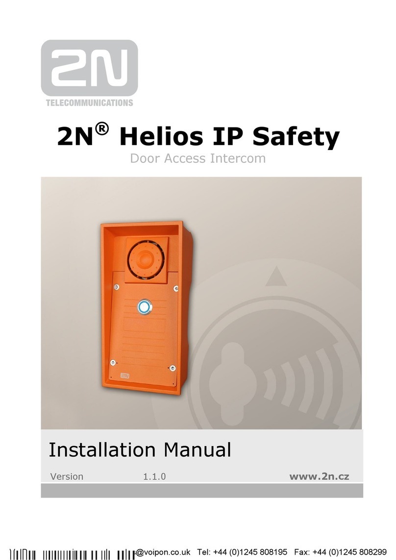
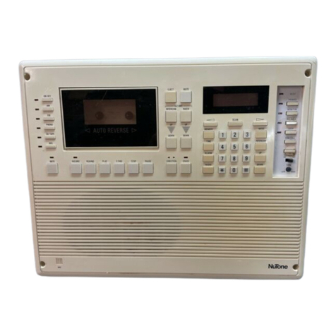
iGuard FPS110 Series User manual

iGuard FPS110 Series Operation Manual
Version 3.4.xxxx (Aug 10
th
, 2004)
Copyright © 2002 Lucky Technology Limited
www.lucky-tech.com
1
iGuard
FPS110 Series
Operation Manual
Version 3.4.xxxx

iGuard FPS110 Series Operation Manual
Version 3.4.xxxx (Aug 10
th
, 2004)
Copyright © 2002 Lucky Technology Limited
www.lucky-tech.com
2
Federal Communications Commission (FCC) Statement
This Equipment has been tested and found to comply with the limits for a Class A
digital device, pursuant to Part 15 of the FCC rules. These limits are designed to
provide reasonable protection against harmful interference in a residential
installation. This equipment generates, uses and can radiate radio frequency
energy and, if not installed and used in accordance with the instructions, may
cause harmful interference to radio communications. However, there is no
guarantee that interference will not occur in a particular installation. If this
equipment does cause harmful interference to radio or television reception, which
can be determined by turning the equipment off and on, the user is encouraged to
try to correct the interference by one or more of the following measures:
- Reorient or relocate the receiving antenna.
- Increase the separation between the equipment and receiver.
- Connect the equipment into an outlet on a circuit different from that to which the
receiver is connected.
- Consult the dealer or an experienced radio/TV technician for help.
CE
EMC DIRECTIVE 89/336/EEC (EN55022 / EN55024)
Trade Name : iGuard
Model No: FPS110 / LM

iGuard FPS110 Series Operation Manual
Version 3.4.xxxx (Aug 10
th
, 2004)
Copyright © 2002 Lucky Technology Limited
www.lucky-tech.com
3
Table of Content
1. INSTALLATION...................................................................................................5
1.1. Quick Installation.........................................................................................5
1.1.1. Pre-Installation Notes .............................................................................5
1.1.2. Installation ................................................................................................5
1.2. Power Requirements ..................................................................................7
1.3. Deciding where to install ............................................................................7
1.4. **Important** Mounting the Metal Back Panel........................................7
1.5. Connections - Power & external controls ................................................7
1.6. Connections - Corporate Network ............................................................9
2. CONFIGURATION............................................................................................11
2.1. Setting the date and time.........................................................................11
2.2. Setting the Network & TCP/IP address .................................................11
2.3. The Company Code..................................................................................13
2.4. Setting the Administrator Password & Access Password...................13
3. BASIC OPERATION.........................................................................................17
3.1. ENROLLMENT ..........................................................................................17
3.1.1. Enrollment with fingerprint ...............................................................17
3.1.2. Enabling Automatch..........................................................................19
3.1.3. Enrollment with Smart Card (for Models with Smart Card reader)20
3.1.4. Internal Memory vs. Smart Card Memory .....................................21
3.1.5. Registering an existing Smart Card ...............................................21
3.2. VERIFICATION..........................................................................................22
3.2.1. Verification with Fingerprint .............................................................22
3.2.2. Verification with Automatch .............................................................23
3.2.3. Verification with Smart Card............................................................23
3.2.4. Verification with Password...............................................................24
3.3. OTHER FUNCTIONS...............................................................................24
3.3.1. Suspending Resuming User............................................................24
3.3.2. Deleting ID..........................................................................................25
3.3.3. Resetting the device .........................................................................25
3.3.4. Emergency Procedures....................................................................25
4. ADMINISTRATION ...........................................................................................26
4.1. Using Web Brower ....................................................................................26
4.2. Employee List ............................................................................................27
4.2.1. Employee List – Internal Memory.......................................................27
4.2.2. Employee List – Smart Card Memory................................................29
4.3. Employee List - Add Employee...............................................................31
4.4. Department - List.......................................................................................32
4.5. Department - Add Department................................................................34
4.6. Access Control - Quick Access...............................................................35
4.7. Administration - Terminal Status.............................................................35
4.8. Administration - Password Setup ...........................................................36
4.9. Administration - Terminal Setup .............................................................37
4.10. Administration - Clock Setup...............................................................37
4.11. Administration - In / Out Trigger.............................................................38
4.12. Administration - Holiday Setup............................................................39
4.13. Administration - Terminal List..............................................................40
4.14. Administration - Add Access Log........................................................41
4.15. Tools - Export Employee......................................................................42

iGuard FPS110 Series Operation Manual
Version 3.4.xxxx (Aug 10
th
, 2004)
Copyright © 2002 Lucky Technology Limited
www.lucky-tech.com
4
4.16. Tools - Backup & Restore....................................................................42
4.17. Tools - Web Camera.............................................................................44
5. REPORTING......................................................................................................46
5.1. Tools-Export (XLS)....................................................................................46
5.2. Tools - Exports (TXT) ...............................................................................47
5.3. Reports - Access Log ...............................................................................48
5.4. Reports - Attendance................................................................................50
5.5. iServer.........................................................................................................50
Create Database: ..............................................................................................50
6MASTER-SLAVE/SUPER MASTER..............................................................55
6.1 Master vs. Slave Mode.............................................................................55
6.2 Setting Terminal ID ...................................................................................56
6.3 Super Master (Only for LM Series) .......................................................57
7MISCELLANEOUS............................................................................................58
7.1 Remote Door Relay ..................................................................................58
7.2 Various In/Out Modes...............................................................................60
7.3 Wiegand 26 bits Output............................................................................61
7.4 Fingerprint and Automatch Matching Security .....................................62
7.5 Web Camera Link Setup..........................................................................62
7.6 Web Pages Languages............................................................................64
7.7 Anti-Passback............................................................................................65
7.8 SNTP Time Server....................................................................................66
7.9 Security for Web Access..........................................................................67
7.10 Reset Device..............................................................................................68
7.11 Test Mode...................................................................................................69

iGuard FPS110 Series Operation Manual
Version 3.4.xxxx (Aug 10
th
, 2004)
Copyright © 2002 Lucky Technology Limited
www.lucky-tech.com
5
1. INSTALLATION
1.1. Quick Installation
Before installing your iGuard, it is important to check a few criteria for safe and
easy installation. For this, please read the pre-installation notes as listed below for
your reference as to steps you should take before implementing iGuard.
1.1.1. Pre-Installation Notes
•
The iGuard terminal is designed for indoor installation. If you wish to install it
outdoors, you must beware of not exposing it to water or harsh conditions.
•
During installation you must be sure of grounding the iGuard back metal
panel to Earth to prevent electrical impulses and shocks from affecting
users or the iGuard terminals.
•
To prevent electrical shortage or short-circuits, it is advised not to share the
power supply of the iGuard with any other device, e.g. electrical lock.
•
To ensure safety, do NOT connect the door button to the iGuard terminal.
Instead connect it directly to the door strike, in case of power outage or
other emergencies.
•
To heighten the security level of the premises, do install the external relay
together with the iGuard. This will increase security since the external relay
is placed within office premises and not outdoors, as is the iGuard.
•
Do NOT install the product next to heat emitting sources or in a place
subject to direct sunlight or excessive dust.
•
If smart card reader model is used, please make sure the Company Code is
set. See Configuration.
1.1.2. Installation
Determine the location(s) for installing iGuard, external relay, door lock and power
supply line. Fasten the rear metal panel at the location where the terminal will be
installed. Connect the terminal with the power supply provided by the factory.
iGuard Terminal Connections
•
Terminal #1 - Ground
•
Terminal #2 - + 12V
•
Terminal #3/4 - Normal Open
•
Terminal #4/5 - Normal Close

iGuard FPS110 Series Operation Manual
Version 3.4.xxxx (Aug 10
th
, 2004)
Copyright © 2002 Lucky Technology Limited
www.lucky-tech.com
6
•
Terminal #6/7 - Door Sensor (optional)
•
Terminal #8/9 – Not used
•
Terminal #10/11 - External Alarm (optional)
•
Plug - External Relay Switch (optional)
iGuard can be connected directly to your corporate network via standard RJ-45
cable & TCP/IP protocols. Make sure your computer/notebook has been installed
and configured with the TCP/IP Protocols.
iGuard can also be connected directly to the network card of PC via crossover RJ-
45 cable.
Setting Network and TCP/IP address
•
On your iGuard, press FUNC, enter the default password "123", press
FUNC, press 5.
•
Enter Date + FUNC.
•
Enter Time + FUNC.
•
Enter the device name + FUNC to continue.
•
Enter IP address (depending on your corporate network addressing scheme,
e.g. 192.168.0.101) + FUNC to continue.
•
Enter Subnet Mask (depending on your corporate network addressing
scheme, e.g. 255.255.255.0) + FUNC to continue.
•
Enter Default Gateway + FUNC to continue.
•
Enter DNS (optional) + FUNC to continue.
•
Select Master/Slave Mode (1 for Master or 2 for Slave).
•
Press 1to accept these values or 2to cancel.
To test whether the iGuard is functioning in the network, try to PING the device
from your PC.
•
On your PC, go to Run Command from Start Menu.
•
Type 'ipconfig " to check the IP address of your PC and make sure it is in
the same network as iGuard.
•
Ping the IP address of iGuard, default: 192.168.0.100.
•
If the ping responds the following, the IP is set properly and you are ready to
proceed:
•
C:\> ping 192.168.0.100
> Pinging 192.168.0.100 with 32 bytes of data:
> Reply from 192.168.0.100: bytes=32 time<10ms TTL=128
> Reply from 192.168.0.100: bytes=32 time<10ms TTL=128
> Reply from 192.168.0.100: bytes=32 time<10ms TTL=128
> Ping statistics for 192.168.0.100:
> Packets: Sent = 4, Received = 4, Lost = 0 (0% loss),
> Approximate round trip times in milli-seconds:
> Minimum = 0ms, Maximum = 0ms, Average = 0ms

iGuard FPS110 Series Operation Manual
Version 3.4.xxxx (Aug 10
th
, 2004)
Copyright © 2002 Lucky Technology Limited
www.lucky-tech.com
7
Open your PC web browser, Internet Explorer or Netscape Navigator, and type in
http://192.168.0.100 (IP Address of your iGuard), and you will be able to see
iGuard's web interface in the browser window.
1.2. Power Requirements
iGuard requires a switching DC 12V / 500mA power supply. It is not recommended
that the same power supply to be shared by both iGuard and the door strike
because of the potential back E.M.F. Problem.
**Warning: Please do NOT use other power supplies since this may lead to system failure, and poor or unreliable operation.
1.3. Deciding where to install
iGuard is a wall-mounted unit with a miniscule footprint, and can be conveniently
installed anywhere. However, it is recommended that the iGuard should be
installed as close to the door as possible, so that the user can open the door within
the timeout period, usually 5 seconds by default. Also note the following points:
•
Allow adequate air circulation to prevent internal heat buildup.
•
Do not install the product next to heat-emitting sources, or in a place subject
to direct sunlight and excessive dust.
1.4. **Important** Mounting the Metal Back Panel
The iGuard comes with a metal panel for mounting on the wall. The panel must
be grounded. By doing so, the static electricity that users emit can be discharged
easily to the ground, which would improve the fingerprint images of users.
1.5. Connections - Power & external controls
iGuard provides easy-access terminals for connections to external controls,
including Door Strikes, Door Sensor, Door Open Switch, and External Alarm.

iGuard FPS110 Series Operation Manual
Version 3.4.xxxx (Aug 10
th
, 2004)
Copyright © 2002 Lucky Technology Limited
www.lucky-tech.com
8
Power (12V DC):
Terminals #1 (ground) & #2 (+12V). The power requirement is 12V DC, 150mA
(idle), 500mA (peak).
Door Strike (Terminal 3 - 5):
(3 - 4 Normal Open, 4 - 5 Normal Close). These terminals are connected directly to
the internal relay, rating at 12V / 1A. If the door strike is within this current limit, it
can be directly connected to these terminals. If the system is used solely for Time
Attendance System, these terminals can be left disconnected.
Door Sensor (optional):
Terminals #6 & #7. It provides iGuard the current status of the door (open / close).
If the door is left open for over 10 seconds, iGuard will generate beep sounds to
alert others.
Open Door Switch (No longer used):
Terminals #8 & #9 are not used.
External Alarm (optional):

iGuard FPS110 Series Operation Manual
Version 3.4.xxxx (Aug 10
th
, 2004)
Copyright © 2002 Lucky Technology Limited
www.lucky-tech.com
9
Terminals #10 & #11. This is used for the optional external alarm. If the case of the
device is forced open during operation (such as a break-in), an internal sensor will
trigger this connection, and it will sound the external alarm.
External Relay (optional):
Switch on the right side. To make use of the external relay, you need to connect a
two pin connector to the board of iGuard and then connect it back to the external
relay. This controls the door strike from within the premises, heightening security
and preventing break-ins.
1.6. Connections - Corporate Network
You can connect iGuard directly to your corporate computer network via standard
RJ-45 cabling & TCP/IP protocols. By connecting it to the network, you can
manage & monitor the unit via any standard web browser, such as Microsoft
Internet Explorer & Netscape Navigator.
The connection is very straightforward as shown in the following picture:
Power-up

iGuard FPS110 Series Operation Manual
Version 3.4.xxxx (Aug 10
th
, 2004)
Copyright © 2002 Lucky Technology Limited
www.lucky-tech.com
10
After the powering up, iGuard will perform a self-test, then it will enter the standby
mode as shown below: -
Description
LCD Display
Initializing…
Power Up -- when iGuard is power-up, it will perform
a self-test…
iGuard System
Loading...
After about 10 sec., the device will load the system
program…
Monday 30 13:49
ID#:
After loading the system program, iGuard will enter
the standby mode and is now ready to use.

iGuard FPS110 Series Operation Manual
Version 3.4.xxxx (Aug 10
th
, 2004)
Copyright © 2002 Lucky Technology Limited
www.lucky-tech.com
11
2.CONFIGURATION
2.1. Setting the date and time
You need to enter the date and time so that iGuard can time stamp all the access
& time attendance records. Follow these steps to set the system date and time: -
Description
LCD Display
Enter Password: _
While in Standby Mode, press the Func key to enter
the Setup Menu. You will be prompted to enter the
Administrator Password as shown.
Enter Password:
123_
Enter the Administrator Password (default:. 123).
Press 1:
Add/Update ID
:
Press 5: System
Configuration …
Press the Func key to continue. The setup menu will
scroll down slowly as shown.
Date (M/D/Y):
08/30/1999
Enter 5to select the System Configuration menu. The
current date is displayed. If necessary, enter the new
date and then press the Func key to continue.
Time (H:M:S):
13:45:23
After pressing the Func key, the current time is
displayed. Enter the new time then press the Func key
to continue.
Terminal ID:
The system will then ask for the Terminal ID. The
Terminal ID is used to identify the iGuard in your
network, especially if you have installed more than one
(to be continued in the next section).
Note:
iGuard can keep the date & time running without power for approximately two days. Also, there is a software tool for users to
synchronize the clock of the iGuard device with the desktop PC (iSetClock.exe), which can be downloaded freely at the
website.
2.2. Setting the Network & TCP/IP address
You can connect iGuard directly to your corporate network. To do so, you would
need to assign a device name & an IP address to the product. It is possible to use

iGuard FPS110 Series Operation Manual
Version 3.4.xxxx (Aug 10
th
, 2004)
Copyright © 2002 Lucky Technology Limited
www.lucky-tech.com
12
the DHCP server in your network to dynamically assign the IP address, but it is
suggested to assign a static IP address to the product to avoid problems.
The following procedures show you how to assign the name, the IP addresses,
and other related settings. Collect all the information before proceeding.
Description
LCD Display
Enter Password:
_
While in Standby Mode, press the Func key to enter
the Setup Menu. You will be prompted to enter the
Administrator Password (default:. 123) as shown.
Press 1:
Add/Update ID
:
Enter 5to select the System Configuration menu.
Press 5: System
Configuration …
Pressing the Func key until you see “DHCP/Static IP”
DHCP/Static IP
(1/2)? Static
Press Func key to continue, and then press 1 to select
DHCP or 2to select Static IP.
IP Address:
192.168.001.123
Press Func key to continue. You will then be asked to
enter the IP address of the device. The default is
192.168.0.100. Enter the static IP address assigned to
the device (e.g., 192.168.1.123).Note: Please
configure the IP according to your corporate
network.
Subnetmask:
255.255.255.000
Press Func key to continue. Enter the sub-net mask
here (e.g., 255.255.255.0).
DefaultGateway:
192.168.000.200
Press Func key to continue. Enter the address of the
Default Gateway (e.g., 192.168.0.200).
DNS:
192.168.000.200
Press Func key to continue. Enter the address of the
Domain Name Server (e.g., 192.168.0.200). Make sure
that the IP address of all units are unique. (Warning: IP
addresses that are not unique will cause network
error and the iGuard would not function.
Press Func key to continue. You will be asked if the Master/Slave
(1/2)? Master

iGuard FPS110 Series Operation Manual
Version 3.4.xxxx (Aug 10
th
, 2004)
Copyright © 2002 Lucky Technology Limited
www.lucky-tech.com
13
device is a Master or Slave device (1/2)? If you have
only one unit of iGuard, choose (1) Master. If you have
more than one units of iGuard, you have to decide
which is the Master and which are the Slave(s). If you
choose (2) Slave, the system will ask you to provide the
Master IP Address, key in, default: 192.168.0.100.
Please also read the section about Master and Slave
mode.
Mon Aug 30 13:46
ID #:_
iGuard FPS110 can be configured as Master or Slave
device. Select one and then press Func key. The
system will reset itself and then return to Standby
Mode.
2.3. The Company Code
The Company Code is introduced for the units with the Smart Card option. The
Company Code is used to make sure that the unit only reads the smart cards
issued by the company. For example, if the Company Code of the unit is 1234, it
only reads the smart cards with the same Company Code, and will ignore the
cards with different company code.
All the units in the same company must have the same company code, and this
company code should be kept confidentially. The company code is set up in the
web page Administration - Terminal Setup via the web browser.
Please note that in the Master / Slave configuration, all the Slave units should have
the same company code as the Master unit.
2.4. Setting the Administrator Password & Access Password
iGuard has three "global” passwords1. The System Administrator Password is
used to access the system menu and to configure the system (such as accessing
the setup menu in the last example). The User Administrator Password is used
to manage the user accounts. The Door Access Password is used to release the
door strike in Quick Access option.
Follow these steps to assign & edit the three passwords:
Description
LCD Display
While in Standby Mode, press the Func key to enter System Admin:
123_

iGuard FPS110 Series Operation Manual
Version 3.4.xxxx (Aug 10
th
, 2004)
Copyright © 2002 Lucky Technology Limited
www.lucky-tech.com
14
the Setup Menu. Enter the System Administrator
Password (default 123) and press Func key, then
press 6to select "Set Password" menu. The menu
"Admin/Personal (1/2)?" will display. Press 1to select
Administrator password.
System Admin:
AB456_
Press the to erase the old password, and enter the
new password (e.g., AB456). The field size limit for
individual passwords is 10 digits, from 0-9 and A/B.
User Admin: _
Press the Func key to accept the new System
Administrator Password. You will then be prompted for
the User Administrator Password as shown.
User Admin:
7890BA_
Enter the new User Administrator Password (e.g.,
7890BA).
Door Access: _
Press the Func key to accept the new User
Administrator Password. You will then be prompted for
the Door Access Password as shown.
Door Access:
9394AB709_
Enter the new Door Access Password (e.g.,
9394AB709). It is suggested to use a long and hard-to-
guess password.
Mon Aug 30 13:49
ID #:_
Press Func to return to the standby mode.
Note:
You must enable the Door Access Password before it can be used, by specifying
the corresponding authorized time and terminals. It is disabled in the factory
settings. The only way to enable it is via the Internet browser (discussed in later
sections), under the “Quick Access" page as follows: -

iGuard FPS110 Series Operation Manual
Version 3.4.xxxx (Aug 10
th
, 2004)
Copyright © 2002 Lucky Technology Limited
www.lucky-tech.com
15
As shown in the figure above, there is no authorized time assigned in the default
setting, and none of the terminals is selected neither. You must specify the
authorized period by first clicking on any one of the Day buttons (i.e., Sunday to
Saturday and Holiday buttons), then select the desire time period (in 30-min
interval). The following figure shows a typical setting: -
After specifying the authorized time and terminals, you can gain access using the
Door Access Password, and it is illustrated in the following steps: -

iGuard FPS110 Series Operation Manual
Version 3.4.xxxx (Aug 10
th
, 2004)
Copyright © 2002 Lucky Technology Limited
www.lucky-tech.com
16
More details about using the Internet browser will be discussed in later sections.
1You should not confuse these Global Passwords with the Personal Password, which can be assigned uniquely to each
individual. More details about the Personal Password will be discussed in later sections.
Description
LCD Display
Enter Password:
_
Press the Func key while in the Standby Mode.
You will then be asked to enter the password.
Enter Password :
*********
Enter the Door Access Password (such as
9394AB709). The password is shown as astride
for security reason.
Mon Aug 30 13:49
ID #:_
Press the Func key again to proceed. If the password
is right, iGuard will release the door strike, and will
return to the Standby Mode.

iGuard FPS110 Series Operation Manual
Version 3.4.xxxx (Aug 10
th
, 2004)
Copyright © 2002 Lucky Technology Limited
www.lucky-tech.com
17
3.BASIC OPERATION
3.1. ENROLLMENT
3.1.1. Enrollment with fingerprint
Fingerprint enrollment is to register a fingerprint template for later recognition. A
good enrollment is crucial for all reliable fingerprint recognition systems, including
the iGuard.
iGuard takes advantage of the advanced DFX (Difficult Fingerprint Extraction)
technology (originally developed by Bell Labs USA), which works accurately with
most people's fingerprint images. iGuard can achieve an exceptionally low false-
rejection-rate of less than 1 %.
However, as individuals, our hands have different levels of moisture. In some
cases, iGuard may have difficulty in recognizing specific users' fingerprint images,
most commonly, people with dry skin. The problem is more noticeable during the
enrollment process since the sensor requires a more accurate and higher quality
fingerprint image than the normal verification process. The easiest way to get
around this problem is to apply a small amount of moisturizing lotion on our fingers
during the enrollment process. This step is only required in the enrollment stage,
and will not be needed in daily verification process.
In the case of poor fingerprint quality or dry finger, iGuard will ask you if you want
to lower the matching security. A low security level will bring more convenience to
the user but with a minor sacrifice of security. We recommend to choose low
security only for time attendance application.
Each person must register two fingers: one as the primary and the other one as the
secondary. In case that the primary finger is not suitable for verification such as
when the finger is hurt, the person can use his/her secondary finger for the
authentication process.
During the process, each fingerprint image is captured three times for minutiae
analysis and extraction. If the quality of any one of the three images is not good
enough, you will be asked to re-capture the three images again.
It is suggested to use your two thumbs as your primary and secondary fingers. It is
because your thumbs are usually bigger and can cover the scanner area better.
IMPORTANT: During the enrollment process, you must position the center of your
fingerprint of your thumb to the center of the fingerprint sensor. The center of the
fingerprint contains the most minutia points from which the fingerprint sensor can
extract. A good fingerprint image captured during the enrollment process can
significantly reduce the false-reject rate during later verification.

iGuard FPS110 Series Operation Manual
Version 3.4.xxxx (Aug 10
th
, 2004)
Copyright © 2002 Lucky Technology Limited
www.lucky-tech.com
18
The following steps show you how to register the user's fingerprint template:
Description
LCD Display
Enter ID # and
scan 1st Finger
While in standby mode, press the Func key to
enter the Setup Menu. Enter the Administrator
Password (default 123) and press Func key, then
press 1to select "Add /Update ID" menu.
Enter ID# A01_
Enter the user ID # (e.g. A01). The ID can be of
any length from 1 character to 8 characters.
Scanning 1 of 3...
:
:
Scanning 1 of 3...
Press the Func key to confirm the ID #. The
device now begins to capture the 1
st
image of the
primary finger. The horizontal bar on the second
line indicates the quality of the image. Lift the
sensor shutter with your right-hand thumb and
place it firmly on the sensor until the quality bar
reaches the right end. You may need to move and
rotate the thumb a little bit to achieve the required
quality.
Analyzing. Pls
remove finger...
After the quality bar reaches the right end, you will
be asked to remove the finger from the sensor.
Press Fun
c to scan
2 of 3
When the device detects that you have removed the
finger, it will ask you to place it back again for the 2
nd
image.
Press Func to scan
3 of 3
Press the Func key and repeat the same procedure,
and you will be asked to scan the 3
rd
time of the same
primary finger.
Press Func to scan
2nd Finger
Press the Func key again and repeat the procedure for
the third time. You will then be asked to scan the
secondary finger.
ID: A01 Added OK!
:
:
Press the Func key, and repeat the above steps to
scan the left-hand thumb three times again. If all the
images are OK, you will see the acknowledge
message "ID: A01 Added OK!" momentary, then the
device is ready for next enrollment.
Enter ID # and
scan 1st Finger

iGuard FPS110 Series Operation Manual
Version 3.4.xxxx (Aug 10
th
, 2004)
Copyright © 2002 Lucky Technology Limited
www.lucky-tech.com
19
Mon 30 Aug 12:00
ID #:_
Press to return to the standby mode.
Scanning 1 of 3
=== Too Dry !===
In the case of dry finger (poor fingerprint image), it will
warn you for dry finger. You can either wet your finger
with lotion and try again, or continue.
Set Security to
Low2 yes(1)/No(2)?
If continue with dry finger, at the end, it will prompt
you if you want to set security to low2. We
recommend to choose low security only for time
attendance application.
3.1.2. Enabling Automatch
This feature enables the device to identify a person without requiring the user to
first enter his/her user ID, and must be turn on via the Internet browser, as
described in the next section. All that needs to be done is to present your enrolled
finger to the sensor and wait for it to match your fingerprint template with stored
templates. Once a match is made, the door opens and the system will then return
to the standby mode.
The maximum number of users allowed to access the iGuard using automatch is
recommended to be limited to 30 users. This is due to the fact that the iGuard
would require some time to process the fingerprint and then search for it across
ALL the database stored on your iGuard. It is therefore recommended that the
automatch feature is left for top management and the rest of staff can use ID plus
Fingerprint for access. Also, user with poor fingerprint quality shall not use
automatch.
Description
LCD Display
Enter ID #: _
While in the standby mode, press the Func key to
enter the Setup Menu. Enter the Administrator
Password (default 123) and press Func key, then
press 8to select "Toggle Automatch ID" menu.
Enter ID #: A01_
Enter the ID # you want to enable automatch (e.g.,
A01). Then, press the Func key to confirm

iGuard FPS110 Series Operation Manual
Version 3.4.xxxx (Aug 10
th
, 2004)
Copyright © 2002 Lucky Technology Limited
www.lucky-tech.com
20
3.1.3. Enrollment with Smart Card (for Models with Smart Card reader)
The user has to be created prior to use this function either the fingerprint is
enrolled or the password is added. After the enrollment procedure, the user ID and
the fingerprint template is stored in the internal memory.
Please note that only one (the primary ) fingerprint template is stored on the smart
card.
The following steps illustrate how to write the user information to a Smart Card:-
Description
LCD Display
Enter ID #: _
While in the standby mode, press the Func key to
enter the Setup Menu. Enter the Administrator
Password (default 123) and press Func key, then
press 9to select “Issue/Import Card" menu. Press 1to
issue Smart Card.
Enter ID #: A01_
Enter the ID # you want to write to the Smart Card
(e.g., A01).
Waiting for
SmartCard...
Press the Func key to confirm. You will then be asked
to present the Smart Card.
Writing....
Present a Smart Card near the keypad. The unit will
then write the user information to the card.
Del ID fm Memory
Yes(1)/No(2)?
After writing to the card, you will be asked whether or
not to remove the user's fingerprint information from
the internal memory. It is recommended not to remove
user fingerprint information from memory.
Enter ID #: _
The unit will prompt for another ID.
Mon Aug 30 12:00
ID #:_
Press key once or wait till time out, the unit will
return to the standby mode.
Other manuals for FPS110 Series
1
Table of contents
