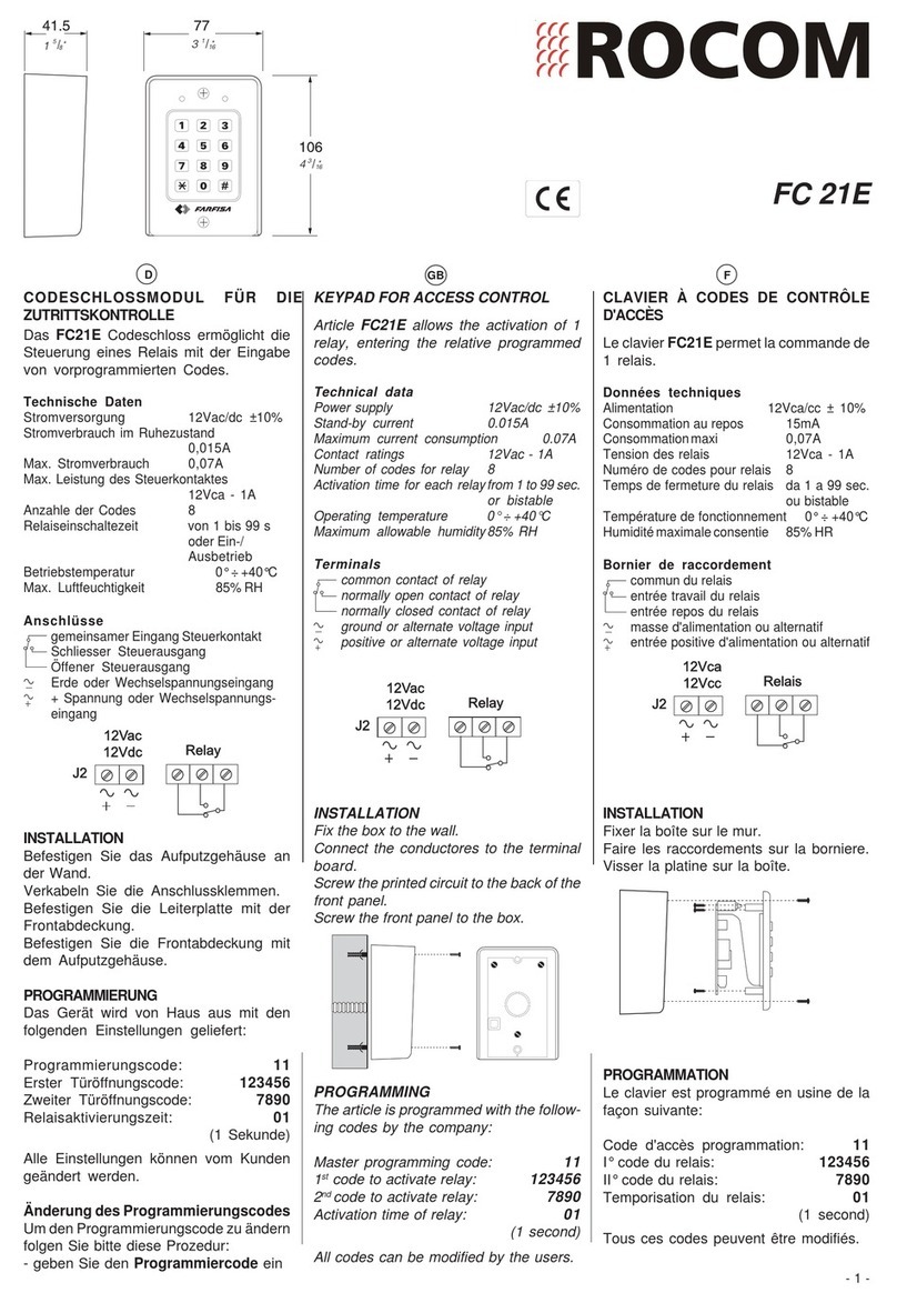
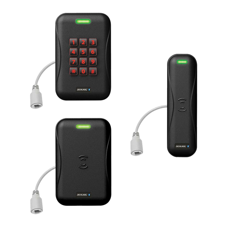
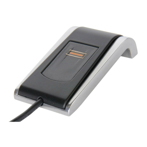
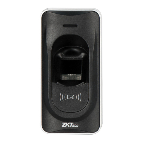
Northern Computers EntryProx User manual

EntryProx™
Quick Reference
Installation Guide
TD1131 rev0800

EntyProx™Installation Introduction
Table of Contents
Introduction . . . . . . . . . . . . . . . . . . . . . . . . . . . . . . . . .i
Product Overview . . . . . . . . . . . . . . . . . . . . . . . . . . . .ii
Installing EntryProx . . . . . . . . . . . . . . . . . . . . . . . . . . . .1-1
Wiring EntryProx . . . . . . . . . . . . . . . . . . . . . . . . . . . . . .2-1
Programming Hints . . . . . . . . . . . . . . . . . . . . . . . . . . .3-1

Installation Introduction EntyProx™

Installation Introduction EntyProx™
i
INTRODUCTION
This User’s Guide is intended for experienced installers of the
EntryProx unit. It is not intended for routine use and does not replace
the more comprehensive information contained in the EntryProx
Installation/Programming Manual. The Guide provides basic informa-
tion and instructions for installing, wiring, and programming the
EntryProx unit.
• For product specifications and functional descriptions, refer to
the Product Overview section.
• For instructions on installation methods and wiring diagrams,
refer to the Installing and Wiring sections.
• For information on available programming options, refer to the
Programming section.
If you experience problems when installing or wiring the EntryProx
unit, please contact your local EntryProx distributor.

EntyProx™Installation Introduction
ii
PRODUCT OVERVIEW
The EntryProx Access Control unit provides card and keypad access
control for a single entrance. The unit can be installed in a typical
one-stage configuration or a higher security two-stage (remote)
configuration. The EntryProx unit is compatible with all HID proximity
cards up to 37 bits. Manual or batch programming can only be com-
pleted with a 26-bit card. All programming options are performed
using the controller keypad.
Unit Capacity
The EntryProx unit can accommodate up to 2,000 users. Each user
can have a card/tag, a PIN code, or a card/tag PLUS a PIN code.
Transactions
A maximum of 1,000 transactions can be stored in the EntryProx
unit. Each transaction includes the time, the date, the user “slot
number,” and the event.

Installation Introduction EntyProx™
iii
T
ABLE
1: F
ACTORY
S
UPPLIED
P
ARTS
L
IST
D
ESCRIPTION
A. Controller Keypad Unit G. Press to Exit label
B. Controller Keypad Backplate H. Silicone Rubber "Dogbone"
C. Cable Asse blies I. Self-Adhering Pads
D. Antenna Backplate J. 2-pin Ju per
E. Antenna Housing K. Filler Piece
F. Mounting Screws
Figure 1: EntryProx Assembly Parts
T
ABLE
2: I
NSTALLER
S
UPPLIED
P
ARTS
L
IST
D
ESCRIPTION
Appropriate DC power supply Power supply cable (18AWG-22AWG)
Appropriate electrical tools Door lock cable (18AWG-22AWG)
Recommended remote antenna cable
ALP A 1174C (22AWG) Door monitor cable (18AWG-22AWG)
Wiegand interface cable ALP A
1295C (22AWG) (only if using a
separate Wiegand control panel)
Request to Exit cable (if using remote
switch)

EntyProx™Installation Introduction
iv
TABLE 3: SPECIFICATIONS
CATEGORY REQUIREMENTS
ENVIRONMENTAL
Operating Temperature -20°Fto130°F
(-28° C to 54° C)
Operating Humidity 5% to 95% relati e humidity, non-
condensing
ELECTRICAL
Power Supply/Current Requirements
(Does not include locking de ice or
peripherals, include both de ices in
your current requirements
calculations.)
10 15 VDC, linear filtered and
regulated power supply recommended
150 mA
MECHANICAL
Height 5.25 in (13.3 cm)
Width 2.75in(7cm)
Depth 1.375 in (3.5 cm)
RELAY OUTPUTS
Main Relay Form C (switches up to 4A)
AuxRelay FormC(switchesupto1A)
SOUNDER
4000 Hz, defeatable
LEDs
Bi-Color (red/green) Amber
TABLE 4: DEFAULT SETTINGS
PARAMETER DEFAULT SETTING
Master Code (user one) 1234*
Main Relay energizes for 5 seconds
Audible Keypress Feedbac ON
Local Propped Door Sounder activates after 30 seconds
Local Forced Door Sounder activates after 10 seconds
Printer Output Port Infrared (IR) port

Installation Section 1 EntyProx™
1-1
Section 1 - Installing the EntryProx
You can install the EntryProx unit by using a standard installation
method or a secure installation method. In a standard installation
the antenna housing remains intact with the controller keypad. A
standard installation involves:
• Mounting the EntryProx unit outside a secured area, such as
outside a main entrance.
• Wiring the EntryProx unit for door locks and alarm out-puts. In
a secure installation the antenna housing is removed from the
controller keypad and mounted outside a secured area. The
blank filler piece is then inserted into the controller keypad in
its place.
Note: If you enable the Request to Exit function, apply the "Press
to Exit" label to the filler piece. Refer to the "Wiring the Request to
Exit Switch" section for more information.
A secure installation involves:
• Mounting the EntryProx unit in a secured area, such as inside
a main reception area.
• Wiring the EntryProx unit for door locks and alarm out-puts.
• Mounting the Antenna Housing.
• Attaching the Press to Exit label (optional).
Note: If you use the secure installation method, you need to
mount and wire the antenna housing no more than 10-feet away
from the controller keypad unit.

FIGURE 2: REMOVING THE WIRING EXITS AND MOUNTING HOLES
Installation Section 1 EntyProx™
1-2
Mounting the EntryProx Unit
To mount the EntryProx unit to a wall surface, refer to Figure 2
and follow these instructions.
Instructions:
1. Remove the hex screw located at the bottom of the
EntryProx unit.
2. Disconnect the backplate of the EntryProx unit from the front
controller keypad.
3. Remove the wire exits and mounting hole cut-outs from the
backplate as shown in Figure 2.
Note: If you mount the EntryProx unit to a glass surface DO NOT
remove the wire exits on the backplate. Remove the appropriate
wire exit cut-outs located on each side of the controller keypad
case.
4. Attach the backplate to a wall or glass surface using the
mounting screws or the self-adhesive fasteners.
Mounting
Holes

EntyProx™Installation Section 1
1-3
Wiring the Controller Keypad for a Standard Installation
To wire the EntryProx unit for a standard installation, refer to
Figures 3 and 4 and follow these instructions.
Instructions:
1. Touch a grounded object BEFORE touching the main circuit
board to guard against possible static discharges.
2. Remove the main circuit board by pushing outward on the
two spring tabs in the direction shown in Figure 3.
3. Lift the main circuit board.
Note: A ribbon cable holds the main circuit board to the controller
keypad board. DO NOT CUT OR REMOVE this cable from its
connector.
4. Make the wiring connections for the door locks and alarm
outputs. Refer to the “Wiring EntryProx” section for appro-
priate wiring diagrams.
FIGURE 3: REMOVING THE CIRCUIT BOARD

Installation Section 1 EntyProx™
1-4
5. Pull the wires through the backplate as shown in Figure 4.
6. Reattach the main circuit board to the controller keypad unit.
7. Attach the controller keypad unit to the mounted backplate
and secure the EntryProx unit with a hex screw or tamper
screw.
FIGURE 4: PULLING THE WIRES THROUGH THE BACKPLATE

EntyProx™Installation Section 1
1-5
Wiring the Controller Keypad for a Secure Installation
In a secure installation, the antenna housing is removed from the
controller keypad and is located no more than 10 feet away from
the EntryProx unit. To wire the EntryProx unit for a secure installa-
tion, refer to Figures 5 and 6 and follow these instructions.
Instructions:
1. Touch a grounded object BEFORE touching the main circuit
board to guard against possible static discharges.
2. Remove the main circuit board by pushing outward on the
two spring tabs in the direction shown in Figure 3.
3. Lift the main circuit board.
Note: A ribbon cable holds the main circuit board to the controller
keypad board. DO NOT CUT OR REMOVE this cable from its
connector.
4. Unplug the four-pin connector P4 from the main circuit
board. See Figure 5.
5. Release the antenna housing from the controller keypad by
pressing inward on the four securing tabs.
6. Remove the antenna housing from the controller keypad by
pushing forward as shown in Figure 6.
P4 Connector
Cable Assembly
FIGURE 5: REMOVING THE P4 CONNECTOR

Installation Section 1 EntyProx™
1-6
7. Insert the extra 10-inch antenna cable assembly into con-
nector P4.
8. Splice in additional antenna cable Alpha 1174C (22AWG) up
to a maximum of 10 feet.
Note: The Alpha 1174C antenna cable is not supplied with the
EntryProx unit.
9. Pull the additional antenna cable through the mounted back-
plate as shown in Figure 4.
10. Make the wiring connections for the Request to Exit switch,
the door locks, and the alarm outputs. Refer to the “Wiring
EntryProx” section for appropriate wiring diagrams.
11. Reattach the main circuit board to the controller keypad
unit.
12. Attach the controller keypad unit to the mounted backplate
and secure the EntryProx unit with a hex screw or tamper
screw.
13. Run the additional antenna cable to the antenna housing
location.
14. Mount and wire the antenna housing.
FIGURE 6: REMOVING THE ANTENNA HOUSING

EntyProx™Installation Section 1
1-7
Mounting and Wiring the Antenna Housing for a Secure
Installation
To mount and wire the antenna housing, refer to Figures 7 and 8
and follow these instructions.
Instructions:
1. Position and secure the antenna backplate to the mounting
surface so that the two moisture release holes are on the
bottom.
2. Pull the antenna cable assembly through the backplate’s
cable holes.
3. Attach the antenna housing to the backplate by inserting the
four securing tabs into the backplate.
4. Cut the plastic connector off the antenna cable assembly.
5. Splice in the additional antenna cable. Be careful to match
the wire colors to the proper pin connectors on the 10-inch
antenna cable assembly.
6. Seal the wire holes with silicone.
FIGURE 8: ATTACHING THE ANTENNA HOUSING
Moisture
Release
Holes
FIGURE 7: MOUNTING THE ANTENNA BACKPLATE

Installation Section 1 EntyProx™
1-8
Selecting a Filler or Request to Exit Operation
The filler piece replaces the antenna housing on the controller key-
pad when you use the secure installation. If you are not going to
use the filler piece as a Request to Exit switch:
• Insert the filler piece into the opening on the controller key
pad.
• Apply the blank label.
If you are going to use the filler piece as a Request to Exit switch:
• Remove the two plastic side tabs on the filler piece.
• Apply the “Press to Exit” label to the filler piece.
• Insert the silicone rubber “dogbone” over the two aligned pins
on the switch activator.
• Insert the filler piece into the opening on the controller key
pad.
• Set the internal request to exit switch to ON. Refer to Table 6:
Program Commands, Programming Code 30, Option 7
Wiegand
Note: Refer to the “Wiring the Request to Exit Switch” section for
the appropriate wiring diagrams.
FIGURE 9: USING THE FILLER PIECE AS A REQUEST TO EXIT SWITCH

Wiring the EntryProx - Section 2 EntyProx™
2-1
Section 2 - Wiring the EntryProx
This section includes three wiring diagrams:
• Wiring the main relay
• Wiring the auxiliary relay
• Wiring the Request to Exit switch
Figure 10 illustrates the location of the four pin connectors on the
main circuit board. Table 5 on Page 2-2 describes each pin and
its use.
1
2
3
4
5
6
1
2
3
4
5
1 2 3 4
1
2
3
4
FIGURE 10: PIN LOCATOR DIAGRAM

Wiring the EntryProx - Section 2 EntyProx™
2-2
TABLE 5: PIN CONNECTOR DESCRIPTIONS/USES
PIN
CONNECTOR PIN WIRE
COLOR USE
P1 (5-pin)
1
2
3
4
5
Gray
Green
Blue
Black
Red
Main Relay, Normally Closed
Main Relay, Normally Closed
Main Relay, Common
Ground
Power n, +12 VDC
P2 (6-pin)
1
2
3
4
5
6
Green
Gray
Blue
Brown
Orange
White
Aux Relay, Normally Closed
Aux Relay, Normally Closed
Aux Relay, Common
REX Loop (if used) (NO contact)
Door Loop Contact (NC contact)
Loop Common (shared by REX and door loop)
P3 (4-pin)
1
2
3
4
Blue
Brown
White
Green
Not used
Wiegand LED Control, user-assigned
Wiegand Data 1
Wiegand Data 0
P4 (4-pin)
1
2
3
4
Red
Black
White
White
Bi-Color LED (Red +)
Bi-Color LED (Green +)
Antenna +
Antenna -

EntyProx™Wiring the EntryProx - Section 2
2-3
WIRING THE MAIN RELAY
The main relay for the door locking device is wired to connector
P1 on the EntryProx main circuit board. To wire the EntryProx unit
to the door locking device, refer to Figures 11 and 12 and follow
these instructions.
Instructions:
1. Power off the EntryProx unit and remove the controller key
pad from the backplate (if not already removed).
2. Remove the main circuit board from the controller keypad
as shown in Figure 3.
3. Locate connector P1 on the main circuit board.
4. Refer to Figure 11 to make the wiring connections for a Fail-
Secure Strike or Lock.
5. Refer to Figure 12 to make the wiring connections for a
Maglock or Fail-Safe Strike.
FIGURE 11: ELECTRIC STRIKE (FAIL SECURE WIRING DIAGRAM)

Wiring the EntryProx - Section 2 EntyProx™
2-4
6. Reattach the main circuit board to the controller keypad.
7. Reattach the controller keypad to the backplate and secure
the EntryProx unit with a hex screw or tamper screw.
Note: You can make the wiring connections for a gate actuator
(diagram not shown) by connecting the Blue (C) wire and the
Green (N/O) wire directly to the input. DO NOT connect a power
supply to the relay.

EntyProx™Wiring the EntryProx - Section 2
2-5
WIRING THE AUXILIARY RELAY
The EntryProx unit has an auxiliary relay feature that allows for
customized alarm programming. Pins 1, 2, and 3 on the P2
connector can be wired for one of the following alarm outputs:
• Alarm shunt
• Forced or propped door
The alarm shunt operation allows you to use the auxiliary relay to
bypass a door contact that is monitored by a separate alarm
system. If the entry or exit is controlled by the EntryProx unit, an
intrusion alarm will not be generated if the door is opened using an
access card or PIN number. The forced or propped door operation
allows you to use the auxiliary relay to install a local warning, such
as an audible or visual indicator if:
• A door is opened without using an access card or PIN
number at the EntryProx unit.
• A door is legitimately opened but is held open too long.
Note: The auxiliary relay audible and visual indicators and the
door open times can be programmed. Refer to Table 6: Program
Commands for more information.
FIGURE 12: MAGLOCK (FAIL SAFE WIRING DIAGRAM)
Table of contents
