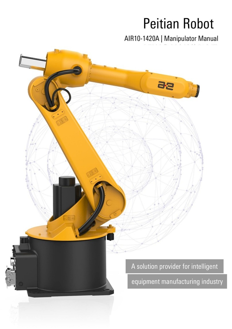
igus Drylin Delta User manual


1

2
Version V1.2-EN, September 2020
© Commonplace Robotics GmbH, 2011 – 2020
igus® , drylin® and robolink® are registered trademarks of igus GmbH.
igus® GmbH
Spicher Str. 1a
51147 Cologne
Germany
Phone Support: +49 (0) 2203-96498-255
www.igus.de, www.igus.eu

3
Table of Contents
1. Safety Instructions .............................................................................................................................. 5
2. Quick Start Guide ................................................................................................................................ 6
2.1. Set up and Connections.............................................................................................................................6
2.2. Switching on ....................................................................................................................................................6
2.3. Connect and Move the Robot ................................................................................................................ 7
3. Introduction ............................................................................................................................................ 8
3.1. System Overview ..........................................................................................................................................8
3.2. Glossary and Abbreviations....................................................................................................................9
3.3. Specifications ................................................................................................................................................ 11
3.4. Mechanical Dimensions .......................................................................................................................... 12
4. Electrical Connections ...................................................................................................................... 13
4.1. Overview .......................................................................................................................................................... 13
4.2. Pinout: Stepper Module .......................................................................................................................... 14
4.3. Pinout: Support Module .......................................................................................................................... 15
4.4. Pinout: Digital Input/Output Module ............................................................................................... 16
4.5. Connect Sensors and Actors to the DIO Module .......................................................................17
4.6. Option: Control Cabinet .......................................................................................................................... 19
4.7. Option: Embedded Computer ............................................................................................................. 20
4.8. Option: Operating Panel ......................................................................................................................... 23
5. Safety .......................................................................................................................................................24
5.1. Safety-Related Features of the Modular Robot Controller .............................................. 24
5.2. CE Certification .......................................................................................................................................... 24
5.3. Integration of SIL-Rated Safety Components .......................................................................... 24
6. Software Installation .......................................................................................................................26
6.1. Installation of the iRC - igus® Robot Control .............................................................................. 26
6.2. Licensing ......................................................................................................................................................... 28
6.3. Setting up the Ethernet Connection to the Embedded Computer ................................. 28
6.4. Installing the CAN-to-USB Driver ..................................................................................................... 29
7. Moving the Robot with iRC ........................................................................................................... 30
7.1. The iRC Graphical User Interface ..................................................................................................... 30
7.2. Connecting the Robot ............................................................................................................................. 32
7.3. Referencing the Robot ........................................................................................................................... 33
7.4. Moving the Robot with Software Buttons or Gamepad ...................................................... 34
7.5. Starting Robot Programs ...................................................................................................................... 36
7.6. Digital Inputs and Outputs .....................................................................................................................37
7.7. Software Interfaces ..................................................................................................................................37

4
7.8. Updating the Software ........................................................................................................................... 38
8. Programming the Robot with iRC ............................................................................................. 39
8.1. The Program Editor .................................................................................................................................. 39
8.2. Comments and Information in Programs ..................................................................................... 42
8.3. Variables and Variable Access .......................................................................................................... 44
8.4. Execution Flow ........................................................................................................................................... 48
8.5. Motion .............................................................................................................................................................. 55
8.6. Gripper and Digital IO ............................................................................................................................... 61
8.7. Camera ............................................................................................................................................................ 62
9. Stand-alone Operation with Embedded Computer and the Operating Panel ..... 63
9.1. Reset Errors/Enable Robot ................................................................................................................ 64
9.2. Moving the Robot with the 3-Axis Joystick ................................................................................ 64
9.3. Referencing ................................................................................................................................................... 65
9.4. Starting and Stopping a Program ..................................................................................................... 65
9.5. Manually Setting the Digital Inputs/Outputs ............................................................................ 66
9.6. Display of Status Information ........................................................................................................... 66
9.7. Organize Programs on the Embedded Control ......................................................................... 67
10. Project Configuration...................................................................................................................... 68
10.1. Program ......................................................................................................................................................... 68
10.2. Tool ................................................................................................................................................................... 68
10.3. Inputs / Outputs......................................................................................................................................... 69
10.4. Virtual Box ..................................................................................................................................................... 70
11. Advanced Robot Configuration .................................................................................................. 70
12. Interfaces Configuration ................................................................................................................. 71
12.1. Cameras ............................................................................................................................................................71
12.2. PLC Interface ................................................................................................................................................ 72
12.3. CRI Ethernet Interface ............................................................................................................................. 72
13. Troubleshooting.................................................................................................................................. 73
13.1. Support Contacts .......................................................................................................................................73
13.2. Online Tool - Fault Identification and Recovery ........................................................................73
13.3. Configuration of the Stepper Modules ......................................................................................... 74
13.4. Calibration of the Robot ......................................................................................................................... 75
13.5. Error Codes ................................................................................................................................................... 76

5
1. Safety Instructions
Operate the Robot safely!
Always ensure personal safety of users and others while operating
a Delta Robot or commissioning a robot cell! In particular, no person
or obstructions may be present in the working area of the Robot.
In its basic version the Robot Controller package does not contain safety related
functionality. Depending on the application, these may need to be added.
See “CE marking” below and Section 5.
CE marking: Delta Robot and the Robot Controller are a part of one system, which must be
risk assessed in its entirety and comply with the current safety regulations to ensure
personal safety. Depending on the result of the assessment further safety components
must be integrated. These are usually safety relays and door switches. Responsible is the
commissioning engineer of the system.
The Robot Controller contains a 24 V power supply unit that itself requires mains voltage
(120 / 240 V), depending on the configuration. Please check the label on the power supply.
Only qualified personnel may connect the power supply to the mains and put it into
operation.
Work on the robot electronics should only be carried out by qualified personnel. Check
current electrostatic discharge (ESD) guidelines.
Always disconnect the Robot Controller from the mains (120 / 240 V) when working in the
Control Cabinet or any electronics connected to the Robot Controller.
Do NOT hot-plug! It may cause permanent damage to the motor modules. Do not install or
remove any modules or plug/unplug connectors (e.g. Operating Panel, Emergency Stop
Button, DIO Modules or external relays, motor connectors) while powered on.
The Delta Robot must be set up on a sturdy surface and bolted down or otherwise
secured.
Only use and store the system in a dry and clean environment.
Only use the system at room temperature (15° to 32°C).
The ventilation of the system must be able to operate without hindrance, to ensure
sufficient airflow to cool the Stepper Motor Driver Modules. There must be at least 10 cm
of space next to the fan of the Robot Controller. The fan must, ideally, point upwards or to
the side (reduced efficiency). The fan must not point down.
Backup important data prior to installing the igus® Robot Control software.

6
2. Quick Start Guide
2.1. Set up and Connections
Follow Safety Instructions, Section 1.
Make sure that the on/off switch on the Control Cabinet is set to "off".
Mount the Robot on a suitable base. Make sure that there is no tension on the cables.
Feed the Robot cables through the large circular hole in the Control Cabinet and plug them
into the Stepper Modules. Each motor is
connected to its Stepper Module via
4 connectors.
All connectors are labeled and coded to aid
this process (see Section 0):
o Motor cable (labelled
Motor
)
o Encoder cable (2 connectors labelled
ENC-1
and
ENC-2
)
o Reference sensor (labelled
End-Stop
)
Secure the robot cables against tension, e.g. with a cable tie to one of the holes in the
Control Cabinet. If available, plug in the display cable and secure it via the screw
connection.
After that the Robot can be connected to the mains.
2.2. Switching on
Switch on the Robot using the on/off switch on
the Control Cabinet.
The green light-emitting diodes (LEDs) on the
modules are now on, also most red LEDs and
potentially some of the yellow LEDs.
Optional: When shipped with an Embedded
Computer, the green LEDs will start flashing
after approx. 20 s. This shows communication,
now the Robot Controller is up and running. If
available, you can now move the Robot using the Operating Panel (optional). Details can
be found in Section 8.

7
2.3. Connect and Move the Robot
Continue with point 2.3.1 or 2.3.2 depending on whether you have an Embedded Computer or
USB-Can adapter supplied with the robot
2.3.1. Preparation using the Embedded Computer
Connect your PC to the Robot Controller via an
Ethernet cable. Use the Ethernet port located
directly next to the USB socket on the embedded
computer of the Robot Controller.
Set the IP address of the PC to:
static and 192.168.3.1
with subnet mask of 255.255.255.0
2.3.2. Preparation using the USB-CAN adapter (
if supplied
)
Connect the USB-CAN-Adapter to a computer (USB port) and the Robot Controller
(D-Sub-9 port with “CAN” marking. Install the necessary driver from the USB memory
stick, see Section 6.2.
2.3.3. Connect and Move the Robot
Install the igus® Robot Control (iRC) software on
your PC, see Section 6.1.
Start the iRC software. On Start-up you can
choose the project suitable for your Robot. Please
refer to the igus product number, the project
names are based on these.
You can now activate the Robot by pressing:
o “Connect”,
o “Reset” and
o “Enable” in sequence.
Now the ‘’Status’’ indicator on the left should be
green, status “No Error”.
You can now move the joints of the robot using the
buttons in the “Jog” tab.
Referencing is mandatory prior to moving in
cartesian coordinates or executing a program.
For details, please refer to Section 7.

8
3. Introduction
3.1. System Overview
The robot system consists of four basic components:
1. Delta Robot : the mechanical linear joints, motors and connectors;
2. Robot Controller : Support Module, Steppermotor Driver and DIO Modules;
3. Robot Control Software: control software to execute robot programs;
4. Programming Environment: graphical software to set up robot programs.
There are two basic system configurations available:
Configuration A uses an Embedded Computer with Robot Control Software to run the
Modular Robot Controller. This set up can execute robot programs without an external
Windows PC connected. For programming an external PC can be connected via Ethernet.
Figure 3.1: Delta Robot with Embedded Computer running the Robot Control Software.
In configuration B a Windows PC serves both as programming environment and to command
the Modular Robot Controller via a USB-CAN adapter. This setup is often used in educational
settings.
Figure 3.2: Delta Robot with Robot Control Software and Programming Environment.
A
B

9
3.2. Glossary and Abbreviations
Image
Name
Abbrev.
Description
igus
®
drylin
®
Delta Robot
Robot
Mechanical robot
arm including
structure, motors
and cables
Modular Robot
Controller
Robot
Controller
Consists of:
1 Support
Module
3 or more
Stepper Modules
1-3 DIO Modules
Control Cabinet
-
Steel cabinet
that
the Robot
Controller can be
mounted in.
Includes a 24 V /
10 A power supply.
Embedded
Computer
-
Optional
Embedded
Computer with
Linux operating
system and the
TinyCtrl Robot
Control Software
Operating
Panel
-
Optional o
perating
hand-held device
with 3.5’’ capacitive
touchscreen
display and 3-axis
joystick

10
Emergency
Stop Button
-
Single
-
channel
emergency stop
Electronic Control Modules
Digital
Input/Output
Module
DIO
Module
Read
s
7 digital
inputs on 24 V level.
Sets 7 digital
output channels
based on Solid
State Relays.
Steppermotor
Driver Module
Stepper
Module
Versions:
Motor Encoder
(ME):
- high current (HC)
- low current (LC)
Output Encoder
(AE):
- high current (HC)
- low current (LC)
Support
Module
-
Provides 5 V logic
voltage, max. 2 A.
Interface for single-
channel Emergency
Stop Button.
Interface for
additional e.g. dual
channel safety
relays.

11
3.3. Specifications
Delta Robot
(if included)
Type
igus
®
drylin
®
Delta Robot
Number of axes
Depending on version
Payload
Depending on version
Modular
Robot Controller
Power supply
24 V
at 10
A
Type
DIN rail modules ME format with 5
-
pin bus connector
Communication
Controller Area Network (CAN) Fieldbus 500
kBit
USB-to-CAN Adapter PCAN-USB from Peak Systems
Ethernet
Support Modules
Provision of 5 V logic voltage: max. 2 A
SoftStart to prevent overloading the power supply
1-channel emergency stop function without safety
classification
Provision to connect external safety relays
Steppermotor Driver Modules
(Stepper Modules)
For operating a bipolar stepper motor
with
quadrature encoder RS422
24 V reference switch input
Digital In/Out Modules
(DIO Module)
7 digital inputs, 12
–
24 V
,
optocoupl
ed
7 digital outputs, solid state relays, max. 500 mA
Embedded Computer
(if included)
Platform
Phytec Regor or comparable
CPU e.g. Texas Instruments AM3352
Operating system
Linux
Software
TinyCtrl Robot Control Software
Interfaces
Control of the drives and DIO Modules via the CAN bus
Connection to igus® Robot Control via Ethernet
RS232 display connection
Programming and Robot Control Software
igus
®
Robot Control
(iRC)
Recommended System
requirements
PC with e.
g.
Intel i
5
CPU
(minimum i3)
and Windows 10,
free USB 2.0 port, ethernet port, 500 MB disk space

12
3.4. Mechanical Dimensions
For more information see the igus® manual “Technical Documentation robolink® DP Version”.

13
4. Electrical Connections
4.1. Overview
Figure 4.1: Overview of electrical connections.

14
4.2. Pinout: Stepper Module
Each Stepper Module drives a bipolar stepper motor with Motor Encoders. The encoder
signals are evaluated by a line driver (RS422).
Signals to each axis travel via three cables: the motor cable, encoder cable and reference
switch cable.
The motor cable is connected to a plug labelled “Motor”, the encoder cable is connected to
two plugs labelled ‘’ENC-1’’ and ‘’ENC-2’’ and the reference switch cable is connected to the
plug labelled “End-Stop”.
Motor connector:
Connects a bipolar stepper motor.
Pin 1 (left): blue B
Pin 2: white A
Pin 3: black B/
Pin 4: brown A/
Encoder connector 1
(ENC
-
1)
:
Connects a quadrature encoder to a line driver.
Pin 1 (left): white A
Pin 2: red 5 V DC
Pin 3: green B
Pin 4: grey 0 V
Encoder connector 2 (ENC-2):
Connects a quadrature encoder to a line driver.
Pin 1 (left): brown A-N
Pin 2: yellow B-N
Pin 3: blue index
Pin 4: pink index-N
All eight wires (encoder connectors 1 and 2) must be
connected to read the encoder.
End
-
S
top connector:
Connects to an end-stop or reference switch.
Pin 1 (left): brown 24 V
Pin 2: blue ground (GND)
Pin 3: black signal
Pin 4 do not connect

15
4.3. Pinout: Support Module
The Support Module provides 5 V logic voltage, a single-channel emergency stop relay,
a SoftStart relay. It feeds the signals into the DIN rail bus system.
Supply voltage connector:
Pin 1 (left): red 24 V
Pin 2: black GND
Pin 3: do not connect -
Pin 4: do not connect -
Controller Area Network (
CAN
)
connector:
Connects controller and CAN-interface of Embedded
Computer.
Pin 1 (left) 5 V to Embedded PC
Pin 2: black CAN-GND
Pin 3: orange CAN-L
Pin 4: red CAN-H
Emergency stop
(E
-
Stop)
connector:
Connects the Emergency Stop Button.
Pin 1 (left): blue E-Stop channel 1
Pin 2: brown 24 V output signal
Pin 3: black E-Stop channel 2
Pin 4: do not connect -
This is a single channel setup, adapt this to your
safety requirements! The options for connecting a
safety relay are described below and in Section 5.
Motor power bridge:
Allows the motor current to be interrupted by
external safety switches, see Section 5.
Pin 1 (left): motor power-out
Pin 2: do not connect
Pin 3: motor-power in
Pin 4: do not connect

16
4.4. Pinout: Digital Input/Output Module
The DIO Module provides input and output channels, e.g. to operate a gripper valve. The
outputs can switch up to 500 mA. The inputs use optocouplers and are compatible to input
Voltages between 12 and 24 V.
A circuit switched by the output relays must not contain any larger capacitors.
If the current exceeds 500 mA, the solid-state relays can suffer damage.
For safety reasons, the inputs and outputs of the DIO Module are electrically isolated. This
means that the circuits of the inputs and outputs are not connected to the internal circuits of
the controller.
It is, therefore, necessary to connect a supply voltage for the outputs and a ground line for the
inputs. For this purpose, the 24 V available in the robot controller can be used, but also an
external independent voltage source. In Software the inputs and outputs of the first
DIO Module are numbered 21-27; the second DIO Module (if supplied) has numbers 31-37; and
the third 41-47.
Digital Out connector
A (
D
-
out
A)
:
The output relays connect the pin of the power
supply with the corresponding output pins.
Pin 1 (left): Input voltage (for all seven channels)
Pin 2: D-Out channel 1 (in software: Dout21)
Pin 3: D-Out channel 2 (in software: Dout22)
Pin 4: D-Out channel 3 (in software Dout23)
Digital Out connector B (D-out B):
The D-out B pins are (from left to right) the
Digital Out channels 4-7 (picture not shown).
Digital In connector
A (
D
-
in
A):
Pin 1 of D-In A is the corresponding GND pin for all
input pins.
Pin 1 (left): Signal GND (for all seven channels)
Pin 2: D-In channel 1 (in software DIn21)
Pin 3: D-In channel 2 (in software DIn22)
Pin 4: D-In channel 3 (in software Din23)
Digital In connector B (D-in B):
The D-in B pins are (from left to right) the Digital In
channels 4-7 (picture not shown).

17
4.5. Connect Sensors and Actors to the DIO Module
The easiest way to connect a programmable logic controller (PLC) is via digital inputs and
outputs. Each Robot Controller comes with one DIO Module. This provides 7 inputs and
7 outputs (see Section 4.4). If additional inputs and outputs are required, up to two additional
DIO Modules can be integrated, see Section 10.1. A total of up to 3 DIO Modules can be
controlled.
The outputs are controlled via solid state relays and can switch up to 500 mA. This value must
not be exceeded during the switching process (e.g. by charging currents of capacitors) to
prevent damage to the relays.
Figure 4.2: Internal set up of a DIO Module.
The inputs and outputs are galvanically separated from the robot control. A power supply
(labelled “IO Supply” in the Figure above) must be connected. The integrated 24 V supply may
also be used.

18
4.5.1.1. To Connect a Sensor
Pin 1 (GND) of the D-In 1 connector must be connected to GND of the power supply
of the sensor.
The sensor signal (positive) must be connected to an input pin D-In 1 connector pins
2-4 or D-In 2 connector pins 1-4.the positive side of the sensor has to be connected
to VDD of the power supply.
The status of the inputs can be monitored in the "Input/Output" tab at the bottom of
iRC, see Section 7.1.
In a robot program inputs can be queried and reacted upon e.g. in an if-then-else
command, see Section 0.
4.5.1.2. To Connect an Actor (LED, pneumatic valve, relay…)
Pin 1 (Supply) of the D-Out 1 connector must be connected to a power supply (e.g.
24 V)
The actor (relay, etc.) is then powered from a free pin of the D-Out connectors
(D-Out 1 pin 2-4 and D-Out 2 pin 1-4).
You can set the outputs manually in the “Input / Output” tab on the bottom of iRC,
see Section 7.1.
In a robot program you can set the state of the outputs using the digital-out
command, see Section 8.6.
Figure 4.3: Connection of an input and output to the DIO Module.

19
4.6. Option: Control Cabinet
The Modular Robot Controller can be ordered in a steel cabinet. The cabinet shields the
control from dust, humidity and accidental access.
The dimensions of the control cabinet are W x L x H: 600 x 200 x 125 mm
Figure 4.4: Control Cabinet, closed. On the lower left the mains IEC connector / switch / fuse and
the cable fittings can be seen.
The cabinet includes a 24 V / 10 A power supply for 220 V / 110 V input. A fuse (8 A).
Distribution blocks are included. A small fan is mounted on the left side of the cabinet.
Figure 4.5: Control Cabinet with Power Supply, without Modular Control Electronics.
Table of contents
Other igus Robotics manuals
