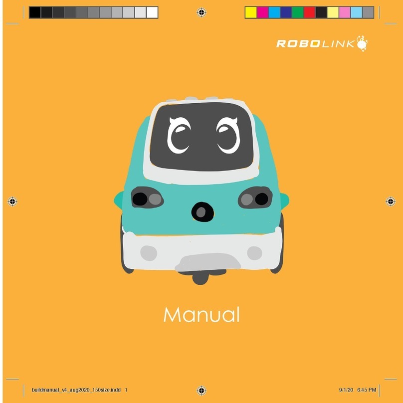
igus robolink User manual

robolink
®
Joint kit – Documentation (#4; 2016-12)
igus
®
robolink
®
Joint kit
Basics..........................................................................................................2
Joint types...................................................................................................3
Articulated arms..........................................................................................4
Angle sensors...........................................................................................11
Actuators...................................................................................................14
Draw wires.................................................................................................15
Mounting instruction cable end bottom..................................................18
Drive pulleys with integrated wire tightening .........................................19
Step motors...............................................................................................20
Drive modules...........................................................................................23
Drive units .................................................................................................24
Accessories...............................................................................................27
Controls.....................................................................................................27
Dimensioned drawings.............................................................................28
Exploded drawings / parts lists................................................................29

robolink
®
Joint kit – Documentation (#4; 2016-12)
igus
®
Basics
igus
®
GmbH develops plastic robotics joints, and produces and harnesses these under
the product group robolink
®
Joint kit. At present, 10 different joint types exist, which can
be combined with each other (status 2015-01).
This provides options to configure and design customized articulated arms for a variety of
customer applications.
Articulated arms can be equipped with angle sensors for positioning purposes. The angle
position of the joint is determined and electronically output (incremental magnetic sensor
system).
A variety of products, such as suction cups, blowers, grippers, camera, light source, etc.,
can be used as actuators (at the end of the articulated arm). Generally, the wires for these
actuators can be fed inside the articulated arm.
Articulated arms are moved with draw wires. One pair of wires each is designed to create
motion for one degree of freedom. The wire pair must be driven in an antagonistic
fashion. This provides for a wide selection of drive technologies. A host of drive
technologies are available, such as: pneumatic drives, electro-motors, but also manual
drives.
igus
®
GmbH offers step motors in various configurations as one possible drive
technology.
The step motors are configured into a drive module by means of a planetary gear and a
drive wheel. The drive wheel is a standardized option to attach and move draw wires.
A drive unit has the same number drive modules as the articulated arm has degrees of
freedom (DOF). igus
®
GmbH offers assembled drive units for a variety of articulated arms
on the basis of step motors with planetary gears in an aluminum housing.
A control (in this case: step motor control) is needed to move a robolink
®
articulated arm.
igus
®
GmbH does not offer or supply these controls and other electrical and electronic
components.

robolink
®
Joint kit – Documentation (#4; 2016-12)
igus
®
Joint types
The following joint types are on offer and can be combined into articulated arms:
Swivel joint RL-50-PL1 +/-90° swivel range
Rotating joints RL-50-TL1 +/-90° rotating range
RL-50-TL2 +/-90° rotating range
Symmetric RL-50-001 +/-90° swivel range
2 axes joint +/-170° rotating range
Asymmetric RL-50-002 +130°/-50° swivel range
2 axes joint +/-170° rotating range
Version without rotation RL-50-PL2 +130°/-50° swivel range
Fully swing in RL-50-003 +180°/0° swivel range
2 axes joint +/-170° rotating range
Version without rotation RL-50-PL3 +180°/0° swivel range
Big base joint RL-90-BL1 +/-90° swivel range
(for 6 DOF arms) +/-90° rotating range
Small base joint RL-50-BL2 +/-90° swivel range
(as “shoulder”) +/-90° rotating range
The swivel ranges are limited by mechanical stop dogs. These can be removed, thus
expanding the swivel range. This is only possible if the wire feed-through is not designed
to be inside the joint (=> Section - Wire feed-through) This option can only be used after
a technical review. Each joint can be optionally equipped with angle sensors.
Nur in Kombination mit RL-90-BL1
only in combination with RL-90-BL1
Fig.1: pivot joint
RL-50-PL1 Fig.2: rotating joint
RL-50-TL1 Fig.3: rotating joint
RL-50-TL1

robolink
®
Joint kit – Documentation (#4; 2016-12)
igus
®
Fig.4: symmetric 2 axes
joint RL-50-001
Fig.5: asymmetric 2 axes
joint RL-50-002
Fig.6: fully swing in 2 axes
joint RL-50-003
Fig.7: Big base joint
RL-90-BL1 (2 axes)
Fig.8: Small base joint
RL-50-BL2 (2 axes)
Articulated arms
The 10 joint types can be used to configure customized articulated arms. Please consider
the following characteristics:
•Rotating joint RL-50-TL1 and base joints RL-90-BL1 and RL-50-BL2 can only be
used as first joints in a multi axes joint arm.
•Rotating joint RL-50-TL2 can only be used in annexation to base joint RL-90-BL1
(“shoulder” kinematics: rotation – pivot – rotation).
•A 6 DOF configuration needs a big base joint RL-90-BL1 as first joint.
•The small base joint RL-50-BL2 is designed for easy humanoid applications with
low additional loads (max. 5 DOF: shoulder and elbow).
•Further joint variants or higher angle range on request.
Standard aluminum tubes (dia = 26 mm) are used as connecting elements between the
joints. The tubes have an inside contour to prevent rotation on the joint interface. The big
base joint RL-90-BL1 is connected by a plain aluminum tube (da = 40 mm), the distorsion

robolink
®
Joint kit – Documentation (#4; 2016-12)
igus
®
lock is given by 4 pcs. M4 screws in this case. Fiberglass (FGC) or carbon-fiber (CFC)
tubes can be selected as alternatives. The tube length is user selectable between l(min)
and l(max) = 1,000mm The minimum length l(min) differs depending on the location in the
system and is defined in Fig. 12 and Fig. 13. The standard length is 100 in each case.
Fig. 9: Interior contour of a connecting tube Fig. 10: Material versions - connecting
tube: FGC, aluminum, CFC
The specifications for the tube lengths, visible tube lengths and rotating point distances
are shown in Figures 7 and 8, along with information for minimum lengths:
X distance of the rotating points to each other, and from the end of the arms,
Y visible tube length,
L true tube length,
1…4 the first figure is always at the beginning of the articulated arm, increasing to a
max. of 4
2 axes joints and swivel joints are designed so that a maximum of 4 wires for each joint
located above can be fed through the joint (=> Section - Draw wires). In addition, each
joint can also feed 3 more cables or hoses with a maximum diameter of 4mm.
The rotating joint can only be the first joint of a series connection, but it can feed up to 8
additional wires, and directly distribute these to the drives in wire pairs.

robolink
®
Joint kit – Documentation (#4; 2016-12)
igus
®
Fig. 11: Tube length information for 1 joint
Fig. 12: Tube length information for combinations of 2 joints

robolink
®
Joint kit – Documentation (#4; 2016-12)
igus
®
This results in certain configuration options of the joints to each other. Articulated arm
versions can be configured with 1 to 6 degrees of freedom (DOF). The following figures
show some possibilities as an example.
RL-P1 RL-T1
RL-01 RL-T1P1 RL-P1P1
Fig. 13: Articulated arms with 1 DOF Fig. 14: Articulated arms with 2 DOF
RL-01P1 RL-P1P1P1 RL-T1P1P1 RL-B1P1
Fig. 15: Articulated arms with 3 DOF
RL-0101 RL-B103 RL-T1P101 RL-T1P1P1P1
Fig. 16: Articulated arms with 4 DOF

robolink
®
Joint kit – Documentation (#4; 2016-12)
igus
®
RL-T10101 RL-T101P1P1 RL-B101P1
Fig. 17: Articulated arms with 5 DOF
RL-B10101 RL-B10301
Fig. 18: Articulated arms with 6 DOF, ordering key
The following technical data corresponds to the system examples shown (at 100 mm tube
length each):
DOF
Fig.
Version
LT
[mm]
(Stand.)
x1*)
[mm] x2*)
[mm] x3*)
[mm] x4*)
[mm]
x
tot
.
[mm]
*)
weight
[gr]
*)
max. stat.
load [N]
*)
max. dyn.
load [N]
*)**)
1
13
RL-T1(-E)
100 173
134
-
-
307
290
89 62
13
RL-P1(-E)
100 134
-
-
-
134
270
89 62
2
14
RL-01(-E)
100 202
134
-
-
336
400
89 62
14
RL-T1P1(-E)
100 207
134
-
-
341
535
89 62
14
RL-P1P1(-E)
100 173
207
134
-
514
555
33 15
3
15
RL-01P1(-E)
100 202
207
134
-
543
665
33 15
15
RL-P1P1P1(-E)
100 173
207
207
134
721
815
18 5
15
RL-T1P1P1(-E)
100 207
207
134
-
548
800
33 15
15
RL-B1P1(-E)
100 252
134
-
-
386
1.585
49 21
4
16
RL-0101(-E)
100 202
236
134
-
572
775
30 12
16
RL-B103(-E)
100 282
134
-
-
416
1.750
44 18
16
RL-T1P101(-E)
100 207
236
134
-
577
910
30 12
16
RL-T1P1P1P1(-E)
100 207
207
207
134
755
1.060
18 5

robolink
®
Joint kit – Documentation (#4; 2016-12)
igus
®
DOF
Fig.
Version
LT
[mm]
(Stand.)
x1*)
[mm] x2*)
[mm] x3*)
[mm] x4*)
[mm]
x
tot
.
[mm]
*)
weight
[gr]
*)
max. stat.
load [N]
*)
max. dyn.
load [N]
*)**)
5
17
RL-T10101(-E)
100 236
236
134
-
606
1.020
30 12
17
RL-T101P1P1(-E)
100 236
207
207
134
784
1.170
18 5
17
RL-B101P1(-E)
100 252
207
134
-
593
1.960
30 9
6
18
RL-B10101(-E)
100 252
236
134
-
622
2.060
29 8
18
RL-B10301(-E)
100 282
236
134
-
652
2.115
28 7,5
*) only applies to geometric configurations with standard tube length = 100mm
**) at 30 RPMs and 0.1 sec. ramp time
Table 1: Specification for articulated arms with 1-6 DOF
All articulated arms can be optionally equipped with angle sensors (=> Section - Angle
sensors). The shown end-plates (for rotating joints) or end-flanges (for 2 axes and swivel
joints) are not part of the delivery scope, but can be ordered as accessories.
When the articulated arm is equipped with a rotating joint, RL-50-TL1, in the first position,
the assembled wires already exit the arm in pairs.
Fig. 19: Dimensioned drawing for an optional mounting plate for the rotating joint, rotating
joint view from below
When the articulated arm is equipped with a 2 axes or a swivel joint in the first position,
the use of a wire splitting unit (RL-WSU8-001) is generally recommended starting at 3
DOF for a controlled distribution of the drive wires.
The 3D STEP data for all articulated arms is available for download at:
www.igus.de/robolink/support&service.

robolink
®
Joint kit – Documentation (#4; 2016-12)
igus
®
Fig. 20: RL-WSU8-001 to connect an articulated arm with a 2 axes or swivel joint in the
first joint
Fig. 21: Dimensioned drawing for an optional mounting plate for the mounting component
RL-WSU8-001

robolink
®
Joint kit – Documentation (#4; 2016-12)
igus
®
Angle sensors
robolink
®
sensors are magnetic incremental angle sensors. Each axis (DOF) has
(optional) one magnetic ring and one associated sensor chip. The magnetic rings are
specified as follows:
Swivel motion RL-50-xxx 31 pole pairs 1 additional south pole
Rotating motion RL-50-xxx 29 pole pairs 1 additional south pole
Swivel and rotating motion RL-90-xxx 29 pole pairs 1 additional south pole
Fig. 22: Magnetic rings - swiveling (1) and
rotating (2) for RL-50-xxx Fig. 23: Sensor unit for 2 axes joint
RL-50-001 /-002 /-003
Fig. 24: Installation situation of the sensor in the joint RL-50-001 /-002 /-003

robolink
®
Joint kit – Documentation (#4; 2016-12)
igus
®
The encoder from Austriamicrosystems (=> Spec sheet download at
www.igus.de/robolink/support&service ) determines 4x40=160 A/B signals per pole pair.
This permits the following resolutions per axis:
Number of pulses
/
chanel
Number of
signals
(Quadratur)
Resolution
Swivel RL-50-xxx 1.240 4.960 0,073°
Rotation RL-50-xxx 1.160 4.640 0,078°
Swivel / Rotation
RL90-xxx 2.480 9.920 0,036°
Fig. 25: A/B and index signals from the encoder
The resolution of the individual axis approximately corresponds to the following
positioning errors at the corresponding tube lengths:
Distance from center point (x) [mm] Positioning accuracy [mm]
200 0,24
400 0,49
500 0,61
Table 2: Positioning accuracy with angle sensors
Since the positioning errors for multiple axis are compounded, system designs have a
positioning inaccuracy, or repeatability accuracy of approx. 1-2mm for multi-axes systems
(depending on the number of axes and tube lengths).
The Hall Sensor Honeywell SS443A is used to reference the system (home position). It
has an Open-Collector-Output. This is designed for the connection to a TTL/CMOS-circuit
– the 10kΩpull-up-resistance exists on the board already.
If the output has to be adapted to a 24V-circuit (e.g. PLC), it is realizable e.g. with the
following circuit diagram with an optical coupler device. The components have to be
adjusted to the respective loads. For this case, a possible electrical configuration is shown
in Fig. 26.

robolink
®
Joint kit – Documentation (#4; 2016-12)
igus
®
Fig. 26: Wiring the Hall sensors
Electrical circuit diagrams for the sensors are at www.igus.de/robolink/support&service .
Each joint axis must be reinitialized (homed) after a power failure.
Each axis (DOF) has 6 conductors. The corresponding strands are assigned as follows:
State
2012-08
producer igus
line name FIXFLEX
FF900.11.282
number of conductors 12
conductor cross section 0,09
line diameter [mm] 3,9
usage from 04.2012
pivoting movement
+5V red
GND black
Hall-Sensor white
Encoder Index green
Encoder Channel A blue
Encoder Channel B yellow
turning movement
+5V red/blue
GND brown
Hall-Sensor grey
Encoder Index grey/rose
Encoder Channel A violet
Encoder Channel B rose
Fig. 27: Cable definition - igus
®
sensor cables

robolink
®
Joint kit – Documentation (#4; 2016-12)
igus
®
Actuators
It is possible to connect various actuators to the last connecting tube of the articulated
arm. We generally recommend a plastic adapter element for this. igus
®
GmbH already
provides standard adapter elements for pneumatic grippers from FESTO
®
and SCHUNK
®
,
for electrical grippers from GIMATIC
®
, and also for suction systems. Cameras or lighting
sources (e.g. LED) can also be adapted.
Fig. 28: standardized adaptable pneumatic grippers
Our own draw wire gripper from igus
®
GmbH can also be mounted on the tube. 2 versions
are possible:
1) Wire force opens, spring force closes,
2) wire force closes, spring force opens.
The spring force can be configured between 20 and 100 N.
(technical documentation of the gripper under design, status 08-2012)
Fig. 29: igus
®
electrical gripper RL-50-GRI-03-xx with standard (left) and universal jaws
(right)

robolink
®
Joint kit – Documentation (#4; 2016-12)
igus
®
Draw wires
The construction kit components are generally driven by draw wires. Standard wires are
made from Dyneema
®
, 12-strand braiding, d=2mm, approx. 1.8 g/m, breaking strength >
3.500 N, operating elongation approx. 1%. A special coating ensures the best possible
service life and low friction.
The wires are installed and held in the joints and the drive (see Fig. 30) by means of wire
end nipples (wire end plate assembly instructions at the end of this chapter).
Fig. 30: Wire (2) with nipple (1) Fig.31 : assembled drive wire in a
tensionable drive wheel
The wire tension in an assembled robolink
®
system should be 5-10 N at idle. The joint has
(generally undesirable) play when the wire tension is inadequate. When the wire tension
is too high, the wire friction in the system and the service life of the wires are negatively
impacted. The tensionable drive wheels from igus
®
(see Fig. 25) are ideally suited for
adjusting the pretension in the draw wires. These come in two parts and can be easily
adjusted to the correct pretension by hand or with an igus
®
tensioning tool (instructions at
the end of this chapter). Readjusting the antagonistic draw wires is generally only needed
during initial operation (2-3 times) or after extended down-time.
The wire guidance for rotating motions is accomplished with Bowden cable segments
from igus
®
GmbH. For this application, the Bowden cables fulfill the following
requirements:
•high compressive strength up to max. 1,500 N wire tension force;
•continuous motion possible, because the segments are made from RN54 material;
•low bending radii, optionally as small as 30mm.
Fig. 32: igus
®
Bowden
cable Fig. 33: Bowden cable segments / schematic

robolink
®
Joint kit – Documentation (#4; 2016-12)
igus
®
All draw wire components are available for reorder from igus
®
GmbH as replacement
parts or as individual components. The article numbers are:
Wire: RL-SD02-01-xxxx xxxx = desired wire length in mm
Nipple: RL-SD02-SN01 2 parts, brass
Bowden cable: RL-SD02-BZ01-xxxx xxxx = Bowden cable length in mm
Tensionable
drive wheel RL-ZA011-0250-xx xx = shaft diameter of the drive
The following instructions for feeding robolink
®
wires must be observed:
•wires must never travel across sharp edges,
•surfaces that are in contact with moving wires should as flat as possible,
•maintain a bending radius of 30mm for wire deflections,
•always slightly pretension wires in robolink
®
systems (approx. 10N),
•inadequately tensioned wires result in undesirable play in the joint,
•excessively tensioned wires cause increased friction and wear,
•igus
®
GmbH recommends using tensionable drive wheels, RL-ZA011-0250-xx,
•igus
®
GmbH recommends using the igus
®
Bowden cable RL-SD02—BZ01 to feed
wires on sections that are not straight,
•whenever possible, feed wires in a straight line and in a free-floating manner
(minimize the use of Bowden cables),
•using deflection pulleys is only recommended for systems with low loads.
When multiple joints are arranged in series, the draw wires of the upper joint are fed
through the lower joint. In this case, the motion of the upper joint must be independent
from the motion of the lower joint. The 4 draw wires of the second joint are therefore fed
through the first joint in a Bowden cable.
In the current configuration, a maximum of 4 wires can be fed through the lower joint. This
is the reason for the limitation of the number of joints that can be arranged in series.
The following figures show how the wires are fed through a lower joint. This feed-through
is pre-assembled by igus
®
and is not assembled by the customer.

robolink
®
Joint kit – Documentation (#4; 2016-12)
igus
®
Fig. 34: Two wire pairs are fed through the
lower joint Fig. 35: Upper connecting element for
guiding the wire
Fig. 36: Bowden cable segments for
parallel feed-through Fig. 37: Lower connecting element

robolink
®
Joint kit – Documentation (#4; 2016-12)
igus
®
Mounting instruction cable end bottom
1) Overview of the neccessairy accessories
4)
Wetting w
ith Loctite Nr. 4204 (alt. 401)
(1) wire, (2) terminal block, (3) wedge
-
Wire end (with the insert wedge) must
necessarily be wetted with Loctite No. 4204 or
401 (“superglue”)
2) Threading the terminal block onto the wire
5) Mounting the terminal block on the
wedge
-
with a suitable device (pliers with suitable
opening), the terminal block has to be leaded on
the wedge,
-
cable shall not be damaged,
-
bring cable end bottom in the following end
position:
-
threading the terminal block onto the wire (1)
-
smaller diameter (2) of the terminal block first on the
wire, (larger diameter (3) shows for cable-end (4))
3) Insert the wedge into the rope
6) Remove protruding wire
-
Manually insertion of the wedge in the cable end
(with the tip first)
-
Insert wedge as centrally as possible in the rope
-
Insert wedge fully into the rope
-
If necessary / desired remove the overlap with a
scalpel
7) Control / end position
The tree should look after these steps as the
following:
State 25.01.12
!
d
rying time min. 90 minutes before us
e
!
strength/retention with Loctite 4204 > 1.900N
strength/retention with Loctite 401 > 1.400N
strength/retention without Loctite > 190 N
1
2
3
1
2 3
4

robolink
®
Joint kit – Documentation (#4; 2016-12)
igus
®
Drive pulleys with integrated wire tightening
The igus
drive unit is equipped with new pulleys RL-ZA011-0250-xx (since July 2011).
They enable the user to tighten the wires for the robolink arm easily.
The tension of the wires can be adjusted individually:
If the tension is to low: the joint will have play (will bounce).
If the tension is to high: friction in the system will rise, all components will be
wearing faster
1. RL-ZA011-0250-xx (nominal diameter 50mm) 2.
unscrew the 3 screws for ~ 2 turns
3.
tighten the rope with the 3-pin-tool that
is delivered with the drive unit
4.
tighten the 3 screws again after that
All drive pulleys can be adapted to different motor shafts (res. gear shafts) by using
different adapter pieces. The following standard dimensions can be chosen from stock:
•RL-ZA011-0250-05 for shaft diameter 5 mm
•RL-ZA011-0250-06 for shaft diameter 6 mm
•RL-ZA011-0250-08 for shaft diameter 8 mm
•RL-ZA011-0250-08PFN for shaft diameter 8 mm (with feather key groove DIN 6885)
•RL-ZA011-0250-10 for shaft diameter 10 mm
•RL-ZA011-0250-10PFN for shaft diameter 10 mm (with feather key groove DIN 6885)
•RL-ZA011-0250-12 for shaft diameter 12 mm
•RL-ZA011-0250-12PFN for shaft diameter 12 mm (with feather key groove DIN 6885)

robolink
®
Joint kit – Documentation (#4; 2016-12)
igus
®
Step motors
Step motors from igus
®
are one possible drive option for wires. These are bipolar 2-phase
hybrid motors. The following options are available: NEMA17 and NEMA23 step motors
with M12 plug connectors or as strand conductors (cost effective alternative). Technical
documentation can be found in the technical spec sheet (download at
www.igus.de/robolink/support&service).
Tab. 3: Basic technical specs for step motors
Fig. 38: Connector versions:
MOT-AN-S-060-005-042-M-A-AAAA (NEMA17)
MOT-AN-S-060-020-056-M-A-AAAA (NEMA23)
Fig. 39: Strand conductor versions:
MOT-AN-S-060-005-042-L-A-AAAA (NEMA17)
MOT-AN-S-060-020-056-L-A-AAAA (NEMA23)
Other manuals for robolink
1
Table of contents
Other igus Robotics manuals
