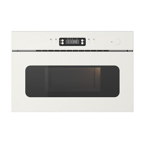
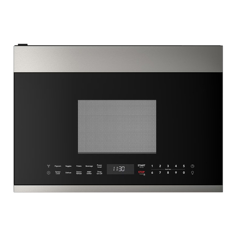
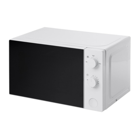
IKEA IMH172DS1 User manual

MICROWAVE HOOD COMBINATION
INSTALLATION INSTRUCTIONS
This product is suitable for use above electric or gas cooking products up to and including 36" (91.4 cm) wide.
The installation instructions cover different models, so the appearance of your particular model may be different from
the illustration version.
COMBINACIÓN MICROONDAS CAMPANA -
INSTRUCCIONES DE INSTALACIÓN
Esta unidad puede usarse encima de productos para cocción eléctricos o a gas de hasta 36" (91,4 cm) de ancho.
Les instructions d'installation couvrent différents modèles; par conséquent, l'aspect de votre modèle peut être différent de celui
de la version illustrée.
INSTRUCTIONS D’INSTALLATION
DE L’ENSEMBLE FOUR À MICRO-ONDES/HOTTE
Ce produit est conçu pour l’utilisation au-dessus d’appareils de cuisson électriques ou à gaz de 36" (91,4 cm) de largeur ou moins.
Las instrucciones de instalación abarcan varios modelos, por lo que el aspecto de su modelo específico puede diferir del que aparece
en la ilustración.
MICROWAVE HOOD
COMBINATION SAFETY.........................2
INSTALLATION REQUIREMENTS..........2
Tools and Parts......................................2
Remove Cardboard Template...............3
Location Requirements.........................3
Product Dimensions..............................3
Electrical Requirements ........................4
INSTALLATION INSTRUCTIONS............4
Remove Mounting Plate........................4
Rotate Blower Motor.............................4
Locate Wall Stud(s) ...............................6
Mark Rear Wall ......................................7
Drill Holes in Rear Wall..........................7
Attach Mounting Plate to Wall ..............8
Prepare Upper Cabinet .........................8
Install Damper Assembly ......................9
Install the Microwave Oven...................9
Complete Installation ............................10
VENTING DESIGN SPECIFICATIONS....11
ASSISTANCE ...........................................12
Replacement Parts................................12
Accessories...........................................12
SEGURIDAD DE LA COMBINACIÓN
MICROONDAS CAMPANA .....................13
REQUISITOS DE INSTALACIÓN ............13
Piezas y herramientas...........................13
Quite la plantilla de cartón ....................14
Requisitos de ubicación........................14
Dimensiones del producto....................14
Requisitos eléctricos.............................15
INSTRUCCIONES DE INSTALACIÓN ....15
Retire la placa de montaje ....................15
Rote el motor del soplador ...................15
Ubique el(los) pie(s) derecho(s)
de pared ................................................17
Marque la pared posterior.....................18
Taladre orificios en la pared posterior...19
Ajuste la placa de montaje a la pared...19
Preparación del armario superior .........20
Instale el ensamblaje de la compuerta
de tiro ....................................................20
Instalación del horno de microondas ...21
Complete la instalación.........................22
ESPECIFICACIONES PARA
EL DISEÑO DE LA VENTILACIÓN .........23
ASISTENCIA.............................................24
Refacciones...........................................24
Accesorios.............................................24
SÉCURITÉ DE L’ENSEMBLE FOUR
À MICRO-ONDES/HOTTE......................25
EXIGENCES D’INSTALLATION ..............25
Outillage et pièces.................................25
Dépose du gabarit de carton................26
Exigences d’emplacement....................26
Dimensions du produit..........................26
Spécifications électriques.....................27
INSTRUCTIONS D’INSTALLATION........27
Dépose de la plaque de montage.........27
Réorientation du moteur
du ventilateur.........................................27
Identifier la position du/des poteau(x)
du colombage mural .............................29
Tracé sur le mur arrière .........................30
Perçage de trous dans le mur arrière ...31
Fixation de la plaque de montage
sur lemur................................................31
Préparation du placard supérieur .........32
Installation du module du clapet
anti-reflux
.............................................. 32
Installation du four à micro-ondes........33
Achever l’installation .............................34
SPÉCIFICATIONS / CONCEPTION
DU CIRCUIT D’ÉVACUATION.................35
ASSISTANCE ...........................................36
Pièces de rechange...............................36
Accessoires...........................................36
Table of Contents / Índice / Table des matières
W10823833A

2
INSTALLATION REQUIREMENTS
Tools Needed
Gather the required tools and parts before starting installation.
Read and follow the instructions provided with any tools
listed here.
■Measuring tape
■Pencil
■Masking tape or
thumbtacks
■Scissors
■No. 2 Phillips screwdriver
■No. 3 Phillips screwdriver
for Z\v-20 x 3" bolts
■Drill
■■C\zn" (5 mm), C\," (10 mm),
B\," (16 mm) drill bits
■■C\v" (19 mm) hole saw
■Diagonal wire cutting pliers
■Stud finder
■■M\zn" socket wrench
(or box wrench) for Z\v" x 2"
lag screws
■1½" (3.8 cm) diam. hole
drill bit for wood or metal
cabinet
■Keyhole saw
■Caulking gun and
weatherproof caulking
compound
■Duct tape
Parts Supplied
For information on reordering, see “Replacement Parts” section.
NOTE: The hardware items listed here are for wood studs.
For other types of wall structures, be sure to use appropriate
fasteners.
A BCD E F G
H
A. C\zn-24 x 3" round-head bolts (2)
B. Z\v-20 x 3" flat-head bolts (2)
C. Washers (2)
D. C\zn" toggle nuts (2)
E. Z\v" x 2" lag screws (2)
F. Sheet metal screws (2)
G. Power supply cord bushing (1)
H. Damper assembly (for wall or
roof venting)
Not Shown:
■Upper cabinet template
■Mounting plate (attached to
back of microwave oven)
■Cardboard template (part of
packaging)
■Aluminum grease filters
■Charcoal filters (Depending
on model, charcoal filters may
not be included. See User
Instructions.)
NOTE: Depending on model, aluminum grease filter and charcoal
filter may be combined.
Materials Needed
■Standard fittings for wall or roof venting. See “Venting Design
Specifications” section.
MICROWAVE HOOD COMBINATION SAFETY
You can be killed or seriously injured if you don't immediately
You can be killed or seriously injured if you don't follow
All safety messages will tell you what the potential hazard is, tell you how to reduce the chance of injury, and tell you what can
happen if the instructions are not followed.
Your safety and the safety of others are very important.
We have provided many important safety messages in this manual and on your appliance. Always read and obey all safety
messages.
This is the safety alert symbol.
This symbol alerts you to potential hazards that can kill or hurt you and others.
All safety messages will follow the safety alert symbol and either the word “DANGER” or “WARNING.”
These words mean:
follow instructions.
instructions.
DANGER
WARNING
Tools and Parts

3
Remove Cardboard Template
The cardboard piece from the top of the microwave oven
packaging is perforated. The piece inside the perforation
is for use as a rear wall template.
1. Cut along the perforation to separate the template from the
rest of the cardboard packaging.
2. Set the cardboard template to the side and refer to it during
the “Mark Rear Wall” part of installation.
Location Requirements
Check the opening where the microwave oven will be installed.
The location must provide:
■Minimum installation dimensions. See “Installation
Dimensions” illustration.
■Minimum one 2" x 4" (50.8 x 101.6 mm) wood wall stud and
minimum C\," (10 mm) thickness drywall or plaster/lath within
cabinet opening.
■Support for weight of 150 lbs (68 kg), which includes
microwave oven and items placed inside the microwave
oven and upper cabinet.
■Grounded electrical outlet inside upper cabinet. See
“Electrical Requirements” section.
NOTES:
■If installing the microwave oven near a left sidewall,
make sure there is at least 6" (15.2 cm) of clearance
between the wall and the microwave oven, so that
the door can open fully.
■Some cabinet and building materials are not designed to
withstand the heat produced by the microwave oven for
cooking. Check with your builder or cabinet supplier to make
sure that the materials used will not discolor, delaminate or
sustain other damages.
Special Requirements
For Wall Venting Installation Only:
■Cutout must be free of any obstructions so that the vent
fits properly, and the damper blade opens freely and fully.
For Roof Venting Installation Only:
■If you are using a rectangular to round transition piece,
the 3" (7.6 cm) clearance needs to exist above the
microwave oven so that the damper blade can open freely
and fully. See “Rectangular to Round Transition” illustration
in “Venting Design Specifications” section.
12" (30.5 cm) min.
14" (35.6 cm) max.
30"
(76.2 cm)
min.
A B
upper cabinet and
side cabinet depth
See note below.
30"
(76.2 cm)
typical*
66" (167.6 cm) min.
A. 2" x 4" wall stud
B. Grounded 3 prong outlet
*30" (76.2 cm) is typical for 66" (167.6 cm) installation height.
Exact dimensions may vary depending on type of range/
cooktop below.
NOTE: To ensure good performance, do not obstruct top vent
airflow. If cabinets are deeper than 14" (35.6 cm), the unit must
be spaced out from the wall, using appropriate materials, which
are able to support 150 lbs (86 kg).
29⁷⁄₈" (76.0 cm)
17¹⁄₈"
(43.5 cm)
+/- ³⁄₁₆"
(0.5 cm)
16¹⁄₄"
(41.3 cm)
Up to
16
³⁄₄
"
(42.5 cm)*
*Overall depth of product will vary slightly depending on
door design.
Spacer
14" 14" 14"
Product Dimensions
Installation Dimensions
NOTE: The grounded 3 prong outlet must be inside the upper
cabinet. See “Electrical Requirements” section.

4
INSTALLATION INSTRUCTIONS
Remove Mounting Plate
Depending on your model, the mounting plate may be in
the foam packaging, or it may be attached to the back of
the microwave oven.
NOTE: To avoid possible damage to the work surface, cover
the work surface.
1. Remove any remaining contents from the microwave oven
cavity.
2. If the mounting plate is attached to the back of the microwave
oven, remove it and set it aside.
3. Tape the microwave oven door closed so that door does not
swing open while the microwave oven is being handled.
NOTE: To avoid damage to the microwave oven, do not grip
or use the door or door handle while the microwave oven is
being handled.
A
B
A. Screws
B. Damper plate
2. Keep damper plate and screws together and set aside.
Rotate Blower Motor
The microwave oven is set for recirculation installation. For wall
or roof venting, changes must be made to the venting system.
NOTE: Skip this section if you are using recirculation installation.
Keep the damper assembly in case the venting method is
changed, or the microwave oven is reinstalled in another
location where wall or roof venting may be used.
Wall Venting Installation Only
1. Remove screws attaching damper plate to top of microwave
oven exterior. Slide damper plate toward the front of the
microwave oven and lift up.
Electrical Requirements
Electrical Shock Hazard
Plug into a grounded 3 prong outlet.
Do not remove ground prong.
Do not use an adapter.
Do not use an extension cord.
Failure to follow these instructions can result in death,
fire, or electrical shock.
WARNING
Observe all governing codes and ordinances.
Required:
■A 120 volt, 60 Hz, AC only, 15- or 20-amp electrical supply
with a fuse or circuit breaker.
Recommended:
■A time-delay fuse or time-delay circuit breaker.
■A separate circuit serving only this microwave oven.
GROUNDING INSTRUCTIONS
SAVETHESE INSTRUCTIONS
■ For all cord connected appliances:
The microwave oven must be grounded. In the event of
an electrical short circuit, grounding reduces the risk of
electric shock by providing an escape wire for the electric
current. The microwave oven is equipped with a cord
having a grounding wire with a grounding plug. The plug
must be plugged into an outlet that is properly installed
and grounded.
WARNING: Improper use of the grounding plug can
result in a risk of electric shock. Consult a qualified
electrician or serviceman if the grounding instructions are
not completely understood, or if doubt exists as to whether
the microwave oven is properly grounded.
Do not use an extension cord. If the power supply cord is
too short, have a qualified electrician or serviceman install
an outlet near the microwave oven.

5
A
4. Lift blower motor out of microwave oven.
A. Screws (in recessed holes)
A
A. Blower motor
5. Rotate blower motor 180° so that exhaust ports face
the back of microwave oven, and lower blower motor
back into the microwave oven.
A
A. Exhaust port
6. Reattach blower motor to back of microwave oven
with 2 screws removed in step 3.
7. Reattach damper plate. Make sure damper plate tabs are
inserted into the slots in the top of the microwave oven.
AB
C
D
A. Damper plate
B. Screws
C. Damper plate tabs
D. Slots
8. Secure damper plate with 2 screws removed in Step 1.
A
A. Exhaust port
IMPORTANT: If blower motor is not positioned with flat sides
facing the back of the microwave oven (as shown), performance
will be poor.
6. Reattach blower motor to back of microwave oven with 2
screws removed in Step 3 of “Wall Venting Installation Only.”
Securely tighten screws.
NOTE: If blower motor is not correctly oriented, the 2 screws
removed in Step 3 cannot be reattached to the microwave oven.
7. Reattach damper plate. Make sure damper plate tabs are
inserted into the slots in the top of the microwave oven.
AB
C
D
A. Damper plate
B. Screws
C. Damper plate tabs
D. Slots
8. Secure damper plate with 2 screws removed in Step 1 of
“Wall Venting Installation Only.”
Roof Venting Installation Only
1. Repeat Step 1 from “Wall Venting Installation Only.”
2. Repeat Step 2 from “Wall Venting Installation Only.”
3. Repeat Step 3 from “Wall Venting Installation Only.”
4. Repeat Step 4 from “Wall Venting Installation Only.”
5. Rotate blower motor so that exhaust ports face the top
of microwave oven and flat sides of blower motor face
back of microwave oven. Lower blower motor back into
microwave oven.
3. Remove 2 screws attaching blower motor to back
of microwave oven.

6
Locate Wall Stud(s)
NOTE: If no wall studs exist within the cabinet opening, do not
install the microwave oven.
See illustrations in “Possible Wall Stud Configurations.”
1. Using a stud finder, locate the edges of the wall stud(s) within
the opening.
2. Mark the center of each stud, and draw a plumb line down
each stud center. See illustrations in “Possible Wall Stud
Configurations.”
Possible Wall Stud Configurations
These depictions show examples of preferred installation configurations with the mounting plate.
No Wall Studs at End Holes
Figure 1
No Wall Studs at End Holes
Figure 2
AA
B
C
D
E
E
F
AA
B
C
C
D
E
E
F
NOTE: If wall stud is within 6" (15.2 cm) of the vertical centerline
(see “Mark Rear Wall” section), only recirculation or roof venting
installation can be done.
Wall Stud at End Hole
Figure 3
Wall Studs at End Holes
Figure 4
A,D
B
E
A,D
C
E
C
F
A
A,D
B
C
C
D
E
E
F
A. End holes (on mounting plate)
B. Cabinet opening vertical centerline
C. Wall stud centerlines
D. Holes for lag screws
E. Support tabs
F. Mounting plate center markers

7
Mark Rear Wall
The microwave oven must be installed on a minimum of 1 wall
stud, preferably 2, using a minimum of 1 lag screw, preferably 2.
1. Using measuring tape, find and clearly mark the vertical
centerline of the opening.
A
A. Centerline
2. Align the center markers on the cardboard template (carton
top cap) to the centerline on the wall, making sure it is level,
and that the top of the cardboard template is butted up
against the bottom edge of the upper cabinet.
NOTES:
■If the front edge of the upper cabinet is lower than the back
edge, lower the cardboard template so that its top is level
with the front edge of the cabinet.
■If the cardboard template is damaged or unusable, measure
and mark the wall with the dimensions described in Step 4.
A
C
B
D
A. Rear wall
B. Cardboard template
C. Top of cardboard template must
align with front edge of cabinet.
D. Front edge of upper cabinet
3. Holding the cardboard template in place, mark both holes
in the lower corners, and draw a horizontal line across the
bottom edge of the cardboard template. These represent
the mounting plate’s end holes and bottom edge.
4. Remove the cardboard template and check the markings:
Upper cabinet bottom
Bottom of mounting plate
Mounting plate end hole
15³⁄₄"
(40.0 cm) 17¹⁄₄"
(43.8 cm)
14¹⁄₈"
(35.9 cm)
14¹⁄₈"
(35.9 cm)
Centerline
■The bottom edge line must be 17Z\v" (43.8 cm) from the
bottom of the upper cabinet and must be level.
■The end holes must be 15C\v" (40.0 cm) from the bottom edge
of the upper cabinet and must be on a level line with each
other. They must each be 14Z\," (35.9 cm) from the centerline.
5. With the support tabs facing forward (see illustrations in
“Locate Wall Stud(s)” section), align the mounting plate center
markers to the centerline on the wall, making sure its bottom
edge is aligned to the horizontal line drawn in Step 3, and that
the end holes are properly marked. Make sure the mounting
plate is level.
NOTE: If the cabinets are deeper than 14" (35.6 cm), a customer
supplied spacer must be securely attached to the wall in the
proper position before attaching the mounting plate to the
spacer. See note in “Installation Dimensions” in the “Location
Requirements” section.
6. Holding the mounting plate in place, find the wall stud
centerline(s) drawn in Step 2 of “Locate Wall Stud(s),” and
mark at least 1, preferably 2 hole(s) through the mounting
plate, closest to the wall stud centerline(s). See figures 1, 2
and/or 3 in “Possible Wall Stud Configurations” in “Locate
Wall Stud(s)” section. The blackened holes in the shaded
areas are ideal hole locations.
7. Set the mounting plate aside.
Wall Venting Installation Only
6" (15.2 cm) 6" (15.2 cm)
³⁄₈" (1.0 cm)
Upper cabinet bottom
4" (10.2 cm) Centerline
8. Mark the centerline C\," (1.0 cm) down from the bottom edge
of the upper cabinet.
9. Using measuring tape, measure out 6" (15.2 cm) on both
sides of the centerline, and mark.
10. Measure down 4" (10.2 cm) from the mark made in Step 8,
and mark.
11. Using a straightedge, draw the 2 horizontal, level lines
through the marks made in steps 8 and 10.
12. Draw the 2 vertical, plumb lines down from the marks made
in Step 9 to complete the 12" x 4" (30.5 x 10.2 cm) rectangle.
This is the venting cutout area.
13. Cut a C\v" (19 mm) hole in one corner of the cutout area.
14. Using a keyhole saw, cut out the venting cutout area.
Drill Holes in Rear Wall
In addition to being installed on at least 1 wall stud, the mounting
plate must attach to the wall at both end holes. If the end holes
are not over wall studs, use two C\zn-24 x 3" round-head bolts
with toggle nuts; if 1 end hole is over a wall stud, use 1 lag screw
and one C\zn-24 x 3" round-head bolt with toggle nut; or if both
end holes are over wall studs, use 2 lag screws. Following are 3
installation configurations.
Installation for No Wall Studs at End Holes
(Figures 1 and 2)
1. Drill B\," (16 mm) holes through the wall at both end holes
marked in Step 3 of “Mark Rear Wall.”
2. Drill C\zn" (5 mm) hole(s) into the wall stud(s) at the hole(s)
marked in Step 6 of “Mark Rear Wall.” Refer to figures 1
and 2 in “Possible Wall Stud Configurations” in “Locate
Wall Stud(s)” section.
Installation for Wall Stud at One End Hole (Figure 3)
1. Drill a C\zn" (5 mm) hole into the wall stud at the end hole
marked in Step 3 of “Mark Rear Wall.”
2. If installing on a second wall stud, drill a C\zn" (5 mm) hole into
the wall stud at the other hole marked in Step 6 of “Mark Rear
Wall.” Refer to Figure 3 in “Possible Wall Stud Configurations”
in “Locate Wall Stud(s)” section.
3. Drill a B\," (16 mm) hole through the wall at the other end hole.

8
Installation for Wall Studs at Both End Holes (Figure 4)
1. Drill C\zn" (5 mm) holes into the studs at the end holes marked
in Step 3 of “Mark Rear Wall.”
Attach Mounting Plate to Wall
NOTE: Secure the mounting plate to the wall at both end holes
drilled into the wall studs and/or drywall using either C\zn-24 x 3"
round-head bolts and toggle nuts or Z\v x 2" lag screws.
Refer to illustrations in “Possible Wall Stud Configurations” in
“Locate Wall Stud(s)” section.
No Wall Studs at End Holes (Figures 1 and 2)
NOTE: The mounting plate must be secured to the wall on
at least 1 wall stud as well as at both ends.
1. With the support tabs of the mounting plate facing forward,
insert C\zn-24 x 3" round-head bolts through both end holes
of mounting plate.
2. Start toggle nuts on bolts from the back of the mounting
plate. Leave enough space for the toggle nuts to go
through the wall and to open.
C
A
B
A. C\zn-24 x 3" round-head bolt
B. Mounting plate
C. Spring toggle nut
3. Position mounting plate on the wall.
4. Push the 2 bolts with toggle nuts through the drywall, and
finger tighten the bolts to make sure toggle nuts have
opened against drywall.
A
B
C
D
A. C\zn-24 x 3" round-head bolt
B. Mounting plate
C. Spring toggle nut
D. Drywall
5. Insert lag screw(s) into the hole(s) drilled into wall stud(s) in
Step 2 of “Installation for No Wall Studs at End Holes” in
the “Drill Holes in Rear Wall” section.
6. Check alignment of mounting plate, making sure it is level.
7. Securely tighten all lag screws and bolts.
Wall Stud at One End Hole (Figure 3)
1. With the support tabs of the mounting plate facing forward,
insert a C\zn-24 x 3" round-head bolt through the end hole that
fits over the B\," (16 mm) hole drilled in Step 3 of “Installation
for Wall Stud at One End Hole” in the “Drill Holes in Rear
Wall” section.
D
E
G
U
p
p
e
r
-
c
a
b
i
ne
t
t
e
m
p
l
a
t
e
F
10"
(25.4 cm)
10"
(25.4 cm)
2. Start a toggle nut on the bolt from the back of the mounting
plate. Leave enough space for the toggle nut to go through
the wall and to open.
3. Position mounting plate on the wall.
4. Push the bolt with toggle nut through the drywall, and finger
tighten the bolt to make sure toggle nut has opened
against drywall.
5. Insert a lag screw into the remaining end hole.
6. If installing on a second wall stud, insert a lag screw into the
other hole drilled in Step 2 of “Installation for Wall Stud at
One End Hole” in the “Drill Holes in Rear Wall” section.
7. Check alignment of mounting plate, making sure it is level.
8. Securely tighten the lag screw(s) and bolt.
Wall Studs at Both End Holes (Figure 4)
1. Position mounting plate on the wall.
2. Insert lag screws into both end holes.
3. Check alignment of mounting plate, making sure it is level.
4. Securely tighten the lag screws.
Prepare Upper Cabinet
1. Disconnect power to outlet.
2. Remove all contents from upper cabinet.
3. Place Upper Cabinet Template against the bottom of the
upper cabinet, and attach with tape or thumbtacks. Make
sure the template centerline aligns with the vertical
centerline on the rear wall.
The “rear wall” arrows must be against the rear wall so that
the holes cut into the upper cabinet align with the holes in the
top of the microwave oven.
NOTES:
■If the upper cabinet has a frame around it, trim the template
edges so that it fits inside the frame against the upper cabinet
bottom. The template has trim lines to use as guides.
■If the wall behind the microwave oven (as installed) has a
partial wall covering (for example, tile backsplash), be sure
the “Rear Wall” arrows align to the thickest part of the rear
wall (for example, the thickness of the tiles rather than the
drywall).
4. Make sure the 10" (25.4 cm) dimension from the rear wall to
points “D” and “E” on the template is maintained.
NOTE: If the upper cabinet is deeper than 14" (35.6 cm), Upper
Cabinet Template must be placed the same distance from the wall
as the thickness of the customer supplied spacer. See not in
“Installation Dimensions” in the “Location Requirements” section.

9
A
B
A. Metal cabinet
B. Power supply cord bushing
A B C D
A. Back of microwave oven
B. Damper assembly
C. Damper blade
D. Sheet metal screws
5. Cut the 1Z\₂" (3.8 cm) diameter hole at the circular
shaded area “G” on the template. This hole is for
the power supply cord.
NOTE: If upper cabinet is metal, the supply cord bushing
needs to be installed around the supply cord hole as shown.
6. Drill C\," (10 mm) holes at points “D” and “E” on the template.
These are for two Z\v-20 x 3" bolts and washers used
to secure the microwave oven to the upper cabinet.
For Roof Venting Installation Only
7. Cut C\v" (19 mm) hole at one corner of the shaded rectangular
area “F” on Upper Cabinet Template.
8. Using a keyhole saw, cut out the rectangular area.
Install Damper Assembly
(for wall venting only)
1. Check that damper blade moves freely and opens fully.
2. Position the damper assembly on the back of the microwave
oven so that the damper blade hinge is at the top, and the
damper blade opens away from the microwave oven.
3. Secure damper assembly with 2 sheet metal screws.
Install the Microwave Oven
WARNING
Excessive Weight Hazard
Use two or more people to move and install
microwave oven.
Failure to do so can result in back or other injury.
IMPORTANT: The control side of the microwave oven is the
heavy side. Handle the microwave oven gently.
1. Place a washer on each Z\v-20 x 3" flat-head bolt and place
inside upper cabinet near the C\," (10 mm) holes.
2. Make sure the microwave oven door is closed and
taped shut.
3. Using 2 or more people, lift microwave oven and hang it on
support tabs at the bottom of mounting plate.
NOTE: To avoid damage to the microwave oven, do not grip
or use the door or door handle while the microwave oven is
being handled.
A
B
A. Mounting plate
B. Support tabs
4. With front of microwave oven still tilted, thread power supply
cord through the power supply cord hole in the bottom of the
upper cabinet.

10
5. Rotate microwave oven up toward upper cabinet.
NOTE: If venting through the wall, make sure the damper
assembly fits easily into the vent in the wall cutout.
6. Push microwave oven against mounting plate and hold
in place.
NOTE: If microwave oven does not need to be adjusted, skip
steps 7-9.
7. If adjustment is required, rotate microwave oven downward.
Using 2 or more people, lift microwave oven off of mounting
plate, and set aside on a covered surface.
8. Loosen mounting plate screws. Adjust mounting plate and
retighten screws.
9. Repeat steps 3-6.
10. With the microwave oven centered, and with at least one
person holding it in place, insert bolts through upper cabinet
into microwave oven. Tighten bolts until there is no gap
between upper cabinet and microwave oven.
NOTES:
■Some upper cabinets may require bolts longer or shorter than
3" (7.6 cm). Longer or shorter bolts are available at
most hardware stores.
■Overtightening bolts may warp the top of the microwave
oven. To avoid warping, wood filler blocks (installer to
provide) may be added. The blocks must be the same
thickness as the space between the upper cabinet bottom
and the microwave oven.
A
A. Bolts
For Roof Venting Installation Only
1. Insert damper assembly through the cabinet cutout so
that the long tab of the damper assembly slides under
the raised tabs of the damper plate. Then secure with
sheet metal screw.
NOTE: The screw cannot be installed if the damper assembly
is not positioned as shown.
A B C
D E F
A. Raised tabs
B. Damper assembly
C. Sheet metal screw
D. Upper cabinet cutout
E. Long tab
F. Damper plate
2. Connect vent to damper assembly.
A B
A. Vent
B. Damper assembly (under vent)
Complete Installation
1. Install filters. Refer to the User Instructions
for filter placement.
Electrical Shock Hazard
Plug into a grounded 3 prong outlet.
Do not remove ground prong.
Do not use an adapter.
Do not use an extension cord.
Failure to follow these instructions can result in death,
fire, or electrical shock.
WARNING
2. Plug microwave oven into grounded 3 prong outlet.
3. Reconnect power.
4. Check the operation of microwave oven by placing 1 cup
(250 mL) of water on the turntable and programming a cook
time of 1 minute at 100% power. Test vent fan and exhaust
by operating the vent fan.
5. If the microwave oven does not operate:
■Check that a household fuse has not blown, or that
a circuit breaker has not tripped. Replace the fuse
or reset the circuit breaker. If the problem continues,
call an electrician.
■Check that the power supply cord is plugged into
a grounded 3 prong outlet.
■See the User Instructions for troubleshooting information.
Installation is now complete.
Save Installation Instructions for future use.

11
VENTING DESIGN SPECIFICATIONS
This section is intended for architectural designer and builder/
contractor reference only.
NOTES:
■Vent materials needed for installation are not provided
with microwave hood combination.
■We do not recommend using a flexible metal vent.
■To avoid possible product damage, be sure to vent air
outside, unless using recirculation installation. Do not vent
exhaust air into concealed spaces, such as spaces within
walls or ceilings, attics, crawl spaces or garages.
For optimal venting installation, we recommend:
■using roof or wall caps that have back draft dampers
■using a rigid metal vent
■using the most direct route by minimizing the length of the
vent and number of elbows to provide efficient performance
■using uniformly sized vents
■using duct tape to seal all joints in the vent system
■using caulking compound to seal exterior wall or roof opening
around cap
■not installing 2 elbows together, for optimal hood
performance
If venting through the wall, be sure that there is proper clearance
within the wall for the damper to open fully.
If venting through the roof, and rectangular to round transition
is used, be sure there is at least 3" (7.6 cm) of clearance
between the top of the microwave oven and the transition
piece. See “Rectangular to Round Transition” illustration.
Roof venting Roof cap
Wall venting Wall cap
Rectangular to Round Transition
NOTE: The minimum 3" (7.6 cm) clearance must exist between
the top of the microwave oven and the rectangular to round
transition piece so that the damper can open freely and fully.
A
B
C
E
F
D
3" (7.6 cm)
A. Roof cap
B. 6" (15.2 cm) min. diameter round vent
C. Elbow (for wall venting only)
D. Wall cap
E. 3Z\v" x 10" to 6" (8.3 x 25.4 cm to 15.2 cm)
rectangular to round transition piece
F. Vent extension piece, at least 3" (7.6 cm) high
Recommended Standard Fittings
The following length equivalents are for use when figuring vent
length. See the examples in “Recommended Vent Length.”
A B C
D E F G
A. Rectangular to round transition piece: 3Z\v" x 10" to 6" = 5 ft
(8.3 x 25.4 cm to 15.2 cm = 1.5 m)
B. Roof cap: 3Z\v" x 10" = 24 ft (8.3 x 25.4 cm = 7.3 m)
C. 90° elbow: 3Z\v" x 10" = 25 ft (8.3 x 25.4 cm = 7.6 m)
D. 90° elbow: 6" = 10 ft (15.2 cm = 3 m)
E. Wall cap: 3Z\v" x 10" = 40 ft (8.3 x 25.4 cm = 12.2 m)
F. 45° elbow: 6" = 5 ft (15.2 cm = 1.5 m)
G. 90° flat elbow: 3Z\v" x 10" = 10 ft (8.3 x 25.4 cm = 3 m)

12
Recommended Vent Length
A 3Z\v" x 10" (8.3 x 25.4 cm) rectangular or 6" (15.2 cm) round
vent should be used.
The total length of the vent system including straight vent,
elbow(s), transitions and wall or roof caps must not exceed
the equivalent of 140 ft (42.7 m) for either type of vent. See
“Recommended Standard Fittings” section for equivalent lengths.
For best performance, use no more than three 90° elbows.
To calculate the length of the system you need, add the
equivalent lengths of each vent piece used in the system.
See the following examples:
3Z\v" x 10" (8.3 x 25.4 cm) vent system = 73 ft (22.2 m) total
A B
C
6 ft (1.8 m)
2 ft
(0.6 m)
A. One 3Z\v" x 10" (8.3 x 25.4 cm) 90° elbow = 25 ft (7.6 m)
B. 1 wall cap = 40 ft (12.2 m)
C. 2 ft (0.6 m) + 6 ft (1.8 m) straight = 8 ft (2.4 m)
6" (15.2 cm) vent system = 73 ft (22.2 m) total
A B
C D
6 ft (1.8 m)
2 ft
(0.6 m)
A. Two 90° elbows = 20 ft (6.1 m)
B. 1 wall cap = 40 ft (12.2 m)
C. 1 rectangular to round transition piece = 5 ft (1.5 m)
D. 2 ft (0.6 m) + 6 ft (1.8 m) straight = 8 ft (2.4 m)
If the existing vent is round, a rectangular to round transition
piece must be used. In addition, a rectangular 3" (7.6 cm)
extension vent between the damper assembly and rectangular
to round transition piece must be installed to keep the damper
from sticking.
ASSISTANCE
Call your authorized dealer or service center. When you call, you
will need the microwave oven model number and serial number.
Both numbers can be found on the model and serial number
plate, which is located behind the microwave oven door on the
front frame of the microwave oven.
If you need additional assistance, call us at our toll free number
or visit our website listed in the User Guide.
Replacement Parts
If any of the installation hardware needs to be replaced, call us
at our toll free number listed in the User Guide.
Following is a list of available replacement parts. You will need
your model number located on the front facing of the microwave
oven opening, behind the door.
■Damper Assembly
■Mounting Plate
■Upper Cabinet Template
■Mounting Screw Kit (includes parts A-G in “Parts Supplied”
in the “Tools and Parts” section)
Accessories
Filler Panel Kits are available from your dealer to use when
installing this microwave oven in a 36" (91.4 cm) or 42"
(106.7 cm) wide opening. The filler panels come in pairs.
Each panel is 3" (7.6 cm) wide.
A
A. Filler panels
See your authorized dealer or service center for details.
Filler Panel Kits: 8171336 White
8171337 Black
8171338 Biscuit
8171339 Stainless Steel
99403 Almond

13
REQUISITOS DE INSTALACIÓN
Herramientas necesarias
Reúna las herramientas y piezas necesarias antes de comenzar
la instalación. Lea y siga las instrucciones provistas con
cualquiera de las herramientas enlistadas aquí.
■Cinta de medir
■Lápiz
■Cinta adhesiva protectora
o chinches
■Tijeras
■Destornillador Phillips N° 2
■Destornillador Phillips N° 3
para los pernos de Z\v-20
x 3"
■Taladro
■Brocas de C\zn" (5 mm),
C\," (10 mm), B\," (16 mm)
■Sierra perforadora de C\v"
(19 mm)
■Pinzas cortaalambres de
ángulo
■Detector de pies derechos
■Llave de tubo de M\zn" (para
los tirafondos de Z\v" x 2"
■Broca para un orificio con
un diám. 1½" (3.8 cm)
para el armario de madera
o de metal
■Sierra caladora
■Pistola para calafateo y
masilla para calafateo a
prueba de agua
■Cinta para ductos
Piezas suministradas
Para recibir información sobre cómo volver a pedir, vea
la sección “Refacciones”.
NOTA: Los artículos de ferretería que se enumeran aquí son para
los pies derechos de madera. Para otros tipos de estructuras de
pared, asegúrese de usar los sujetadores adecuados.
A BCD E F G
H
A. Pernos de cabeza redonda
de C\zn-24 x 3" (2)
B. Pernos de cabeza plana de
Z\v-20 x 3" (2)
C. Arandelas (2)
D. Tuercas de ajuste de C\zn"
E. Tirafondos de Z\v" x 2"
F. Tornillos para lámina metálica (2)
G. Forro para el cable de
suministro de energía (1)
H. Ensamblaje de la compuerta de
tiro (para la ventilación a través
de la pared o del techo)
No se muestra:
■Plantilla del armario superior
■Placa de montaje (sujeta a la
parte posterior del horno de
microondas)
■Plantilla de cartón (parte del
embalaje)
■Filtros de aluminio para grasa
■Filtros de carbón (Según el
modelo, tal vez no se incluyan
filtros de carbón. Vea las
Instrucciones para el usuario).
NOTA: Según el modelo, el filtro de aluminio para grasa y el filtro
de carbón pueden combinarse.
Materiales necesarios
■Accesorios corrientes para la ventilación a través de la pared
o del techo. Vea la sección “Especificaciones para el diseño
de la ventilación”.
SEGURIDAD DE LA COMBINACIÓN MICROONDAS CAMPANA
Si no sigue las instrucciones de inmediato, usted puede
morir o sufrir una lesión grave.
Si no sigue las instrucciones, usted puede morir o sufrir
una lesión grave.
Todos los mensajes de seguridad le dirán el peligro potencial, le dirán cómo reducir las posibilidades de sufrir una lesión y lo que
puede suceder si no se siguen las instrucciones.
Su seguridad y la seguridad de los demás es muy importante.
Hemos incluido muchos mensajes importantes de seguridad en este manual y en su electrodoméstico. Lea y obedezca siempre
todos los mensajes de seguridad.
ADVERTENCIA
PELIGRO
Este es el símbolo de advertencia de seguridad.
Este símbolo le llama la atención sobre peligros potenciales que pueden ocasionar la muerte o una lesión a
usted y a los demás.
Todos los mensajes de seguridad irán a continuación del símbolo de advertencia de seguridad y de la palabra
“PELIGRO” o “ADVERTENCIA”. Estas palabras significan:
Piezas y herramientas

14
Quite la plantilla de cartón
La pieza de cartón de la parte superior de la caja del horno
de microondas está perforada. La pieza que está dentro
de la perforación se usa como plantilla para la pared posterior.
1. Corte a lo largo de la perforación para separar la plantilla del
resto del embalaje de cartón.
2. Coloque la plantilla de cartón al costado y tómela como
referencia durante la parte “Marque la pared posterior”
de la instalación.
Requisitos de ubicación
Revise la abertura donde se instalará el horno de microondas.
El lugar debe tener:
■Dimensiones mínimas para la instalación. Vea la ilustración
“Dimensiones de instalación”.
■Un pie derecho de pared de madera como mínimo, de 2" x
4" (50,8 x 101,6 mm) y un panel de cartón yeso o yeso/listón
con un espesor mínimo de C\," (10 mm) dentro de la abertura
del armario.
■Un soporte para un peso de 150 lb (68 kg), el cual incluye
el horno de microondas y los objetos que se coloquen dentro
del mismo, así como también en el armario superior.
■Un contacto eléctrico conectado a tierra dentro del armario
superior. Vea la sección “Requisitos eléctricos”.
NOTAS:
■Si va a instalar el horno de microondas cerca de una pared
lateral izquierda, asegúrese de dejar un espacio de por lo
menos 6" (15,2 cm) entre la pared y el horno de microondas,
para que la puerta se pueda abrir en toda su extensión.
■Algunos armarios y materiales de construcción no
han sido diseñados para resistir el calor que produce
el horno de microondas durante la cocción. Verifique con
el constructor o distribuidor de armarios para asegurarse
de que los materiales que se usen no se descoloren,
astillen ni sufran ningún otro tipo de daño.
Requisitos especiales
Solamente para la instalación con ventilación en la pared:
■El recorte deberá estar libre de cualquier obstrucción para
que el ducto de escape encaje como es debido y la hoja
de la compuerta se abra libre y completamente.
Solamente para la instalación con ventilación en el techo:
■Si usa un tubo de ajuste rectangular a redondo, deberá
haber un espacio de 3" (7,6 cm) por encima del horno de
microondas, para que la hoja de la compuerta pueda abrirse
libre y completamente. Vea la ilustración “Tubo de ajuste
rectangular a redondo” en la sección “Especificaciones
para el diseño de la ventilación”.
A B
12" (30,5 cm) mín.
14" (35,6 cm) máx.
profundidad del
armario superior y
del armario lateral
Vea la nota siguiente.
A. Pie derecho de pared de 2" x 4"
B. Contacto de pared de conexión a tierra de 3 terminales
*30" (76,2 cm) es lo típico para la altura de una instalación
de 66" (167,6 cm). Las medidas exactas pueden variar según
el tipo de estufa/superficie de cocción que esté debajo.
NOTA: Para asegurar un buen desempeño, no obstruya el flujo
de aire y ventilación de la parte superior. Si los armarios tienen
una profundidad mayor a 14" (35,6 cm), debe haber un espacio
entre la unidad y la pared utilizando materiales apropiados para
soportar 150 lb (68 kg).
29⁷⁄₈" (76,0 cm)
16¹⁄₄"
(41,3 cm)
Hasta
16³⁄₄"
(42,5 cm)*
17¹⁄₈"
(43,5 cm)
+/- ³⁄₁₆"
(0,5 cm)
*El ancho total del producto variará ligeramente según el diseño
de la puerta.
Espaciador
14" (35,6 cm) 14" (35,6 cm) 14" (35,6 cm)
Dimensiones del producto
Dimensiones de instalación
NOTA: El contacto de pared de conexión a tierra de 3
terminales debe estar dentro del armario superior. Vea
la sección “Requisitos eléctricos”.

15
INSTRUCCIONES DE INSTALACIÓN
Retire la placa de montaje
Según el modelo, la placa de montaje puede estar en el paquete
de espuma o sujeta a la parte posterior del horno de microondas.
NOTA: Cubra la superficie de trabajo para evitar posibles daños
en la misma.
1. Saque el contenido restante de la cavidad del horno
de microondas.
2. Si la placa de montaje está sujeta a la parte posterior
del horno de microondas, quítela y déjela a un lado.
3. Coloque cinta adhesiva en la puerta del horno de microondas
para que ésta no se abra mientras se manipula el horno
de microondas.
NOTA: Para evitar daños al horno de microondas, no agarre ni
use la puerta o la manija de la puerta mientras manipula el horno
de microondas.
Rote el motor del soplador
El horno de microondas ha sido fijado para la instalación con
recirculación. Para la ventilación a través de la pared o del techo,
deberá modificarse el sistema de ventilación.
NOTA: Saltee esta sección si va a usar la instalación con
recirculación. Conserve el ensamblaje de la compuerta de tiro
en caso de cambiar el método de ventilación o si va a volver
a instalar el horno de microondas en otro lugar en donde pueda
usar la ventilación a través de la pared o del techo.
A
B
A. Tornillos
B. Placa de la compuerta de tiro
2. Mantenga juntos la placa de la compuerta de tiro y
los tornillos y déjelos a un lado.
Solamente para la instalación con ventilación en la pared
1. Saque los tornillos que sujetan la placa de la compuerta a
la parte superior del exterior del horno de microondas.
Deslice la placa de la compuerta hacia el frente del horno
de microondas y levántela.
Requisitos eléctricos
ADVERTENCIA
Peligro de Choque Eléctrico
Conecte a un contacto de pared de conexión a tierra de
3 terminales.
No quite la terminal de conexión a tierra.
No use un adaptador.
No use un cable eléctrico de extensión.
No seguir estas instrucciones puede ocasionar
la muerte, incendio o choque eléctrico.
Cumpla con todos los códigos y ordenanzas vigentes.
Se necesita:
■Un suministro eléctrico de 120 voltios, 60 Hz, CA solamente,
de 15 o 20 amperios protegido con fusible o cortacircuitos.
Se recomienda:
■Un fusible o un cortacircuitos retardador.
■Un circuito separado que preste servicio a este horno de
microondas solamente.
INSTRUCCIONES PARA
LA CONEXIÓN A TIERRA
GUARDE ESTAS
INSTRUCCIONES
■ Para todos los aparatos electrodomésticos de
conexión con cable:
El horno de microondas debe estar conectado a tierra. En
caso de que se produzca un cortocircuito, la conexión a
tierra reduce el riesgo de electrocución por medio de un
alambre de escape para la corriente eléctrica. El horno de
microondas está equipado con un cable que tiene un
alambre de conexión a tierra con un enchufe para
conexión a tierra. El enchufe debe estar conectado a un
tomacorriente que está correctamente instalado y
conectado a tierra.
ADVERTENCIA: El uso incorrecto del enchufe
para la conexión a tierra puede resultar en riesgo de
electrocución. Consulte con un electricista o técnico
calificado si las instrucciones para conexión a tierra no se
entienden bien o si hay alguna duda con respecto a la
correcta conexión a tierra del horno de microondas.
No use un cable de extensión. Si el cable de suministro
eléctrico es muy corto, haga que un electricista o técnico
calificado instale un tomacorriente cerca del horno de
microondas.

16
A
4. Levante y saque el motor del soplador del horno
de microondas.
A. Tornillos (en orificios de rebajo)
A
A. Motor del soplador
5. Rote el motor del soplador 180° de manera que las lumbreras
de escape queden mirando hacia la parte posterior del horno
de microondas y bájelo nuevamente dentro del horno
de microondas.
A
A. Lumbrera de escape
6. Vuelva a sujetar el motor del soplador a la parte posterior
del horno de microondas con los 2 tornillos que quitó en
el paso 3.
7. Vuelva a sujetar la placa de la compuerta de tiro. Cerciórese
de que las lengüetas de la placa de la compuerta de tiro
estén insertadas en las ranuras que están en la parte superior
del horno de microondas.
AB
C
D
A. Placa de la compuerta de tiro
B. Tornillos
C. Lengüetas de la placa de la compuerta de tiro
D. Ranuras
8. Asegure la placa de la compuerta de tiro con los 2 tornillos
que quitó en el paso 1.
A
A. Lumbrera de escape
IMPORTANTE: Si no se coloca el motor del soplador con
los lados planos mirando hacia la parte posterior del horno
de microondas (tal como se muestra), éste tendrá
un rendimiento insuficiente.
6. Vuelva a sujetar el motor del soplador a la parte posterior
del horno de microondas con los 2 tornillos que quitó en
el paso 3 de “Solamente para la instalación con ventilación
en la pared”. Apriete firmemente los tornillos.
NOTA: Si no se orienta el motor del soplador como es debido,
los 2 tornillos que se quitaron en el paso 3 no podrán volver a
sujetarse al horno de microondas.
7. Vuelva a sujetar la placa de la compuerta de tiro. Cerciórese
de que las lengüetas de la placa de la compuerta de tiro
estén insertadas en las ranuras que están en la parte superior
del horno de microondas.
AB
C
D
A. Placa de la compuerta de tiro
B. Tornillos
C. Lengüetas de la placa de la compuerta de tiro
D. Ranuras
8. Asegure la placa de la compuerta de tiro con los 2 tornillos
que quitó en el paso 1 de “Solamente para la instalación
con ventilación en la pared”.
Solamente para la instalación con ventilación en el techo
1. Repita el paso 1 de “Solamente para la instalación con
ventilación en la pared”.
2. Repita el paso 2 de “Solamente para la instalación con
ventilación en la pared”.
3. Repita el paso 3 de “Solamente para la instalación con
ventilación en la pared”.
4. Repita el paso 4 de “Solamente para la instalación con
ventilación en la pared”.
5. Rote el motor del soplador de manera que las lumbreras
de escape queden mirando hacia la parte superior
del horno de microondas y los lados planos del motor
del soplador queden mirando hacia la parte posterior
del horno de microondas. Baje el motor del soplador
nuevamente dentro del horno de microondas.
3. Saque los dos tornillos que sujetan el motor del soplador
a la parte posterior del horno de microondas.

17
Ubique el(los) pie(s) derecho(s) de pared
NOTA: Si no hay pies derechos de pared dentro de la abertura
del armario, no instale el horno de microondas.
Vea las ilustraciones en “Posibles configuraciones de los pies
derechos de pared”.
1. Ubique los extremos del(de los) pie(s) derecho(s) de pared
dentro de la abertura con un detector de pies derechos.
2. Marque el centro de cada pie derecho y trace una línea a
plomo hacia abajo del centro de cada pie derecho. Vea
las ilustraciones en “Posibles configuraciones de los pies
derechos de pared”.
Posibles configuraciones de los pies derechos de pared
Estas representaciones muestran ejemplos de las configuraciones de instalación preferidas con la placa de montaje.
Sin pies derechos de pared en los orificios de los extremos
Figura 1
Sin pies derechos de pared en los orificios de los extremos
Figura 2
AA
B
C
D
E
E
F
AA
B
C
C
D
E
E
F
NOTE: If wall stud is within 6" (15.2 cm) of the vertical centerline
(see “Mark Rear Wall” section), only recirculation or roof venting
installation can be done.
Pie derecho de pared en un orificio del extremo
Figura 3
Pies derechos de pared en ambos orificios de los extremos
Figura 4
A,D
B
E
A,D
C
E
C
F
A
A,D
B
C
C
D
E
E
F
A. Orificios de extremo (en la placa de montaje)
B. Línea central vertical de la abertura del armario
C. Líneas centrales de los pies derechos de pared
D. Orificios para los tirafondos
E. Lengüetas de soporte
F. Marcadores centrales para la placa de montaje

18
El horno de microondas deberá instalarse como mínimo sobre
1 pie derecho de pared, preferentemente 2, usando un mínimo
de 1 tirafondo, preferentemente 2.
1. Con la cinta de medir, ubique y marque claramente la línea
central vertical de la abertura.
A
A. Línea central
2. Alinee los marcadores centrales en la plantilla de cartón
(cubierta superior del empaque) con la línea central en
la pared, asegurándose de que esté nivelada y de que
la parte superior de la plantilla de cartón esté contra
el extremo inferior del armario superior.
NOTAS:
■Si el extremo frontal del armario superior está más bajo
que el extremo posterior, baje la plantilla de cartón para
que la parte superior quede nivelada con el extremo
frontal del armario.
■Si la plantilla de cartón está dañada o no puede usarse,
mida y marque la pared con las dimensiones descritas
en el paso 4.
A
C
B
D
A. Pared posterior
B. Plantilla de cartón
C. La parte superior de la plantilla de cartón deberá
alinearse con el extremo frontal del armario.
D. Extremo frontal del armario superior
3. Sujetando la plantilla de cartón en su lugar, marque ambos
orificios en las esquinas inferiores y trace una línea horizontal
a lo largo del extremo inferior de la plantilla de cartón. Éstos
representan los orificios de los extremos de la placa de
montaje y el borde inferior.
4. Retire la plantilla de cartón y verifique las marcas:
Parte inferior del armario superior
Orificio del e
xtremo
de la placa de montaje
15³⁄₄"
(40,0 cm) 17¹⁄₄"
(43,8 cm)
14¹⁄₈"
(35,9 cm)
14¹⁄₈"
(35,9 cm)
Línea central
Parte inferior de la placa de montaje
■La línea inferior del borde deberá estar a 17Z\v" (43,8 cm) de
la parte inferior del armario superior, y debe estar nivelada.
■Los orificios de los extremos deberán estar a 15C\v" (40,0
cm) del borde inferior del armario superior, y deberán estar
alineados entre ellos. Deberán estar a 14Z\," (35,9 cm) de
la línea central.
5. Con las lengüetas de soporte mirando hacia adelante (vea
las ilustraciones en la sección “Ubique el[los] pie[s] derecho[s]
de pared”), alinee los marcadores centrales de la placa de
montaje con la línea central de la pared, cerciorándose de
que el borde inferior esté alineado con la línea horizontal
trazada en el paso 3, y que los orificios de los extremos
estén debidamente marcados. Cerciórese de que la placa de
montaje esté nivelada.
NOTA: Si los armarios tienen una profundidad mayor a 14"
(35,6 cm), un espaciador provisto por el cliente debe ajustarse
firmemente a la pared en la posición adecuada antes de fijarse
la placa de montaje al espaciador. Vea la nota en “Dimensiones
de instalación” en la sección “Requisitos de ubicación”.
6. Sosteniendo la placa de montaje en su lugar, ubique
la(s) línea(s) central(es) de los pies derechos de la pared
marcada(s) en el paso 2 de “Ubique el(los) pie(s) derecho(s)
de pared”, y marque por lo menos 1, preferentemente 2,
orificios a través de la placa de montaje, lo más cercano a
la(s) línea(s) central(es). Vea las figuras 1, 2 y/o 3 en “Posibles
configuraciones de los pies derechos de pared” en la sección
“Ubique el(los) pie(s) derecho(s) de pared”. Los orificios
ennegrecidos en las áreas sombreadas son las ubicaciones
ideales para los orificios.
7. Deje a un lado la placa de montaje.
Solamente para la instalación con ventilación en la pared
6" (15,2 cm) 6" (15,2 cm)
³⁄₈" (1.0 cm)
Parte inferior del armario superior
4" (10,2 cm) Línea central
8. Marque la línea central C\," (1.0 cm) hacia abajo desde
el borde inferior del armario superior.
9. Usando una cinta de medir, mida hacia afuera 6" (15,2 cm)
a ambos lados de la línea central y marque.
10. Mida hacia abajo 4" (10,2 cm) desde la marca que hizo
en el paso 8 y marque.
11. Trace con una regla 2 líneas niveladas horizontales a través
de las marcas que hizo en los pasos 8 y 10.
12. Trace las 2 líneas verticales a plomo hacia abajo desde
las marcas hechas en el paso 9 hasta completar
el rectángulo de 12" x 4" (30,5 x 10,2 cm). Ésta es el área
de recorte de la ventilación.
13. Corte un orificio de C\v" (19 mm) en una esquina del área
de corte.
14. Corte el área de corte de la ventilación con una sierra
caladora.
Marque la pared posterior

19
C
A
B
A. Perno de cabeza redonda de C\zn-24 x 3"
B. Placa de montaje
C. Tuerca de ajuste con resorte
A
B
C
D
A. Perno de cabeza redonda de C\zn-24 x 3"
B. Placa de montaje
C. Tuerca de ajuste con resorte
D. Panel de yeso
Taladre orificios en la pared posterior
Además de instalar la placa de montaje en al menos 1 pie
derecho, la placa debe sujetarse a la pared en ambos orificios
de los extremos. Si los orificios no están sobre los pies derechos
de pared, use dos pernos de cabeza redonda de C\zn-24 x 3"
con tuercas de ajuste; si 1 orificio está sobre un pie derecho
de pared, use un tirafondo y un perno de cabeza redonda
de C\zn-24 x 3" con una tuerca de ajuste; o si ambos orificios
de los extremos se encuentran sobre los pies derechos de pared,
use 2 tirafondos. A continuación, se incluyen 3 configuraciones
de instalación.
Instalación sin pies derechos de pared en los orificios
de los extremos (figuras 1 y 2)
1. Taladre orificios de B\," (16 mm) a través de la pared, en
los dos orificios de los extremos que se marcaron en
el paso 3 de “Marque la pared posterior”.
2. Taladre uno o más orificios de C\zn" (5 mm) en el(los) pie(s)
derecho(s), en el(los) orificio(s) que se marcó (marcaron) en
el paso 6 de “Marque la pared posterior”. Consulte las figuras
1 y 2 en “Posibles configuraciones de los pies derechos
de pared” en la sección “Ubique el(los) pie(s) derecho(s)
de pared”.
Instalación para pie derecho de pared en un orificio del
extremo (figura 3)
1. Taladre un orificio de C\zn" (5 mm) a través del pie derecho de
pared en el orificio del extremo que se marcó en el paso 3 en
“Marque la pared posterior”.
2. Si va a instalar en un segundo pie derecho de pared, taladre
un orificio de C\zn" (5 mm) en el pie derecho de pared, en
el otro orificio marcado en el paso 6 de “Marque la pared
posterior”. Consulte la figura 3 en “Posibles configuraciones
de los pies derechos de pared” en la sección “Ubique
el(los) pie(s) derecho(s) de pared”.
3. Taladre un orificio de B\," (16 mm) a través de la pared
en el otro orificio del extremo.
Instalación para pies derechos de pared en ambos
orificios de los extremos (figura 4)
1. Taladre orificios de C\zn" (5 mm) en los pies derechos de pared,
en los orificios de los extremos que se marcaron en el paso 3
de “Marque la pared posterior”.
Ajuste la placa de montaje a la pared
NOTA: Asegure la placa de montaje a la pared en ambos orificios
de los extremos que se perforaron en los pies derechos de pared
y/o en el panel de yeso utilizando pernos de cabeza redonda de
C\zn-24 x 3" y tuercas de ajuste o tirafondos de Z\v x 2".
Vea las ilustraciones en “Posibles configuraciones de los pies
derechos de pared” en la sección “Ubique el(los) pie(s) derecho(s)
de pared”.
Sin pies derechos de pared en los orificios de los
extremos (figuras 1 y 2)
NOTA: La placa de montaje debe asegurarse a la pared en por
lo menos 1 pie derecho de pared, como así también en ambos
extremos.
1. Con las lengüetas de soporte de la placa de montaje mirando
hacia adelante, inserte pernos de cabeza redonda de C\zn-24
x 3" a través de ambos orificios del extremo de la placa de
montaje.
2. Coloque las tuercas de ajuste en los pernos comenzando
por la parte posterior de la placa de montaje. Deje suficiente
espacio para que las tuercas de ajuste puedan atravesar la
pared y abrirse.
3. Posicione la placa de montaje en la pared.
4. Empuje los 2 pernos con las tuercas de ajuste a través
del panel de yeso y apriete los pernos con los dedos para
asegurarse que las tuercas de ajuste se hayan abierto contra
el panel de yeso.
5. Inserte el(los) tirafondo(s) en el(los) orificio(s) taladrado(s) en
el(los) pie(s) derecho(s) de pared en el paso 2 de “Instalación
sin pies derechos de pared en los orificios de los extremos”
en la sección “Taladre orificios en la pared posterior”.
6. Controle la alineación de la placa de montaje, asegurándose
de que esté nivelada.
7. Ajuste bien todos los tirafondos y pernos.
Pie derecho de pared en un orificio del extremo (figura 3)
1. Con las lengüetas de soporte de la placa de montaje
mirando hacia adelante, inserte un perno de cabeza
redonda de C\zn-24 x 3" a través del orificio del extremo
que coincida con el orificio de B\," (16 mm) taladrado
en el paso 3 de “Instalación para pie derecho de pared
en un orificio del extremo” en la sección “Taladre orificios
en la pared posterior”.
2. Coloque una tuerca de ajuste en el perno comenzando
por la parte posterior de la placa de montaje. Deje suficiente
espacio para que la tuerca de ajuste pueda atravesar la pared
y abrirse.
3. Posicione la placa de montaje en la pared.
4. Empuje el perno con la tuerca de ajuste a través del panel
de yeso y apriete el perno con los dedos para asegurarse que
la tuerca de ajuste se haya abierto contra el panel de yeso.
5. Inserte un tirafondo en el orificio del extremo restante.
6. Si se hace la instalación en un segundo pie derecho
de pared, inserte un tirafondo en el otro orificio taladrado
en el paso 2 de “Instalación para pie derecho de pared
en un orificio del extremo” en la sección “Taladre orificios
en la pared posterior”.
7. Controle la alineación de la placa de montaje, asegurándose
de que esté nivelada.
8. Apriete con firmeza el(los) tirafondo(s) y el perno.

20
A
B
A. Armario de metal
B. Forro para el cable de suministro de energía
A B C D
A. Parte posterior del horno de microondas
B. Ensamblaje de la compuerta de tiro
C. Hoja de la compuerta de tiro
D. Tornillos para lámina metálica
Pies derechos de pared en ambos orificios de los
extremos (figura 4)
1. Posicione la placa de montaje en la pared.
2. Inserte los tirafondos en ambos orificios de los extremos.
3. Controle la alineación de la placa de montaje, asegurándose
de que esté nivelada.
4. Ajuste firmemente los tirafondos.
Preparación del armario superior
1. Desconecte la energía que alimenta el contacto de pared.
2. Saque el contenido del armario superior.
3. Coloque la plantilla del armario superior contra la base
del armario superior, y sujétela con cinta adhesiva o chinches.
Asegúrese de que la línea central de la plantilla quede
alineada con la línea central vertical en la pared posterior.
Las flechas que indican “pared posterior” deberán estar
contra la pared posterior, para que los orificios que se
cortaron en el armario superior queden alineados con
los orificios que están en la parte superior del horno
de microondas.
NOTAS:
■Si el armario superior tiene un marco alrededor, recorte
los extremos de la plantilla para que encaje dentro
del marco, contra la base del armario superior. La plantilla
tiene líneas de recorte para usarlas como guías.
■Si la pared detrás del horno de microondas (según
se haya instalado) tiene un revestimiento de pared parcial
(como pueden ser baldosas de salpicadero), asegúrese
de que las flechas de la “Pared posterior” se alineen
con la parte más gruesa de la pared posterior (por ejemplo,
el espesor de las baldosas y no el panel de yeso).
4. Asegúrese de mantener la medida de 10" (25,4 cm) desde
la pared posterior a los puntos “D” y “E” en la plantilla.
NOTA: Si el armario superior tiene una profundidad mayor
a 14" (35,6 cm), la plantilla del armario superior debe colocarse
a la misma distancia de la pared que el grosor del espaciador
provisto por el cliente. Vea la nota en “Dimensiones de
instalación” en la sección “Requisitos de ubicación”.
D
E
G
U
p
p
e
r
-
c
a
b
i
ne
t
t
e
m
p
l
a
t
e
F
10"
(25.4 cm)
10"
(25.4 cm)
5. Corte un orificio de 1Z\₂" (3,8 cm) de diámetro en el área
sombreada circular “G” en la plantilla. Este orificio es para
el cable de suministro de energía.
NOTA: Si el armario superior es de metal, el forro del cable de
suministro necesitará ser instalado alrededor del orificio del cable
de suministro, como se muestra.
6. Taladre orificios de C\," (10 mm) en los puntos “D” y “E” de
la plantilla. Éstos son para los dos pernos de Z\v-20 x 3" y
las arandelas usadas para asegurar el horno de microondas
al armario superior.
Solamente para la instalación con ventilación en el techo
7. Corte un orificio de C\v" (19 mm) en una esquina del área
rectangular sombreada “F” en la plantilla del armario superior.
8. Corte el área rectangular con una sierra caladora.
Instale el ensamblaje de la
compuerta de tiro
(solamente para la ventilación a través
de la pared)
1. Verifique que la hoja de la compuerta se mueva libremente y
que se abra completamente.
2. Coloque el ensamblaje de la compuerta de tiro detrás
del horno de microondas, de manera que la bisagra de
la hoja de la compuerta esté en la parte superior, y la hoja de
la compuerta se abra hacia afuera del horno de microondas.
3. Asegure el ensamblaje de la compuerta de tiro con 2 tornillos
para lámina metálica.
Table of contents
Languages:
Other IKEA Microwave Oven manuals

IKEA
IKEA MATÄLSKARE User manual

IKEA
IKEA EFTERSMAK User manual

IKEA
IKEA HUSHALLAFRAMTID MW3 User manual

IKEA
IKEA GRÄNSLÖS User manual

IKEA
IKEA NUTID MWC 6 User manual

IKEA
IKEA IMH16 User manual

IKEA
IKEA FRAMTID MW 3 User manual

IKEA
IKEA FINSMAKARE User manual

IKEA
IKEA MATÄLSKARE User manual

IKEA
IKEA TILLREDA User manual