ii
Ikegami Tsushinki Co., Ltd.
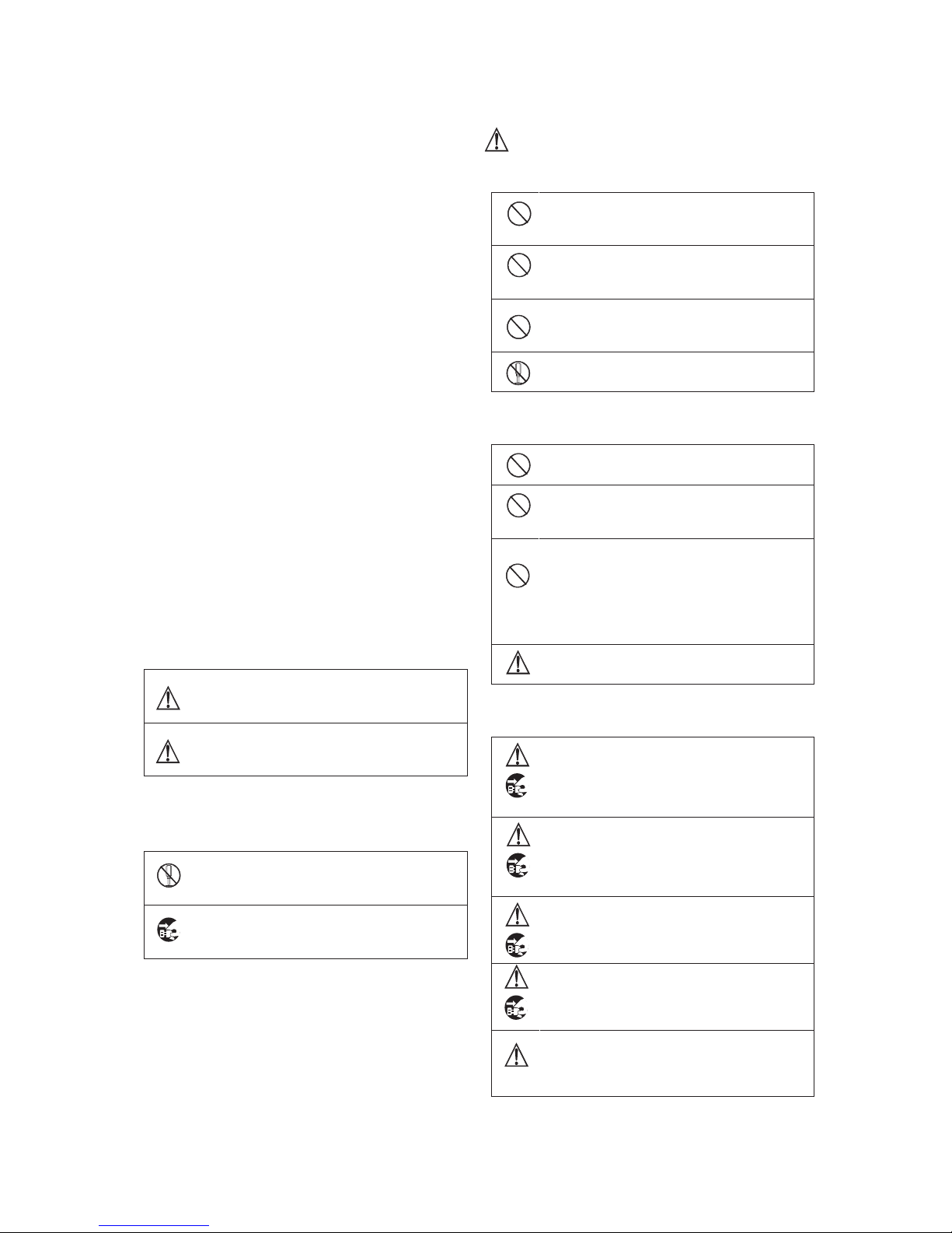
Caution
When you use the product:
Do not place any heavy object on this unit!
By doing so, the unit may lose the balance and fall down or
be dropped down, causing personal injury.
Do not get on or sit on this unit or the carrying case!
The unit may be broken or fall down, resulting in personal
injury.
Before moving the unit, be sure to turn off the power switch
and unplug the power plug from the outlet and disconnect the
connecting cables between devices!
If you fail to do so, the power cord may be damaged,
causing a fire or an electric shock accident.
If the unit is not to be used for a long time, be sure to unplug
the power plug from the outlet for safety.
Failure to do so may cause a fire.
When you install the product:
Do not block the ventilation holes of this unit!
Blocking the ventilation hole may cause heat to build up
inside the unit, causing a fire. Do not use the unit in the
following manner:
•Putting the unit upside down; toppling it over
sideways; or inverting it.
•Pushing unit onto a narrow place with poor ventilation.
•Placing the unit on a soft material such as carpet.
•Covering the unit with a piece of table cloth, etc.
To Use the Product Proficiently
When you use the product:
•When using the unit at a watery location such as near a bath or poolside,
do not allow water to enter this unit or the cables.
The water that has entered the unit or the cables may cause an electric
accident.
Please be especially careful when you use it when it is raining or
snowing; near the beach; or in the kitchen.
•If thunder is heard, be sure to use the unit by considering the operating
environment and the situation.
If required, interrupt the use of the unit, and keep off the unit, or else
you may receive an electric shock.
•Do not connect any device to an AC outlet with a power rating (W)
exceeding the rating allowed for the outlet.
Be sure to check the power rating value indicated near the AC outlet or
the Instruction Manual, or the Operation Manual.
•Do not use the power cord or connecting cables by forcefully bending (or
twisting or pulling) them.
By doing so, the insulation of the cord or cables may be damaged,
causing an electric shock accident to occur.
When you install the product:
•Install the unit by keeping it away from a location exposed to excessive
humidity or dust, oily smoke, or steam.
Installation of the unit on such a location may cause an electric shock.
Do not place the unit near a cooking table or a humidifier.
•Make sure that the unit is securely protected from falling by a sudden
earthquake or a shock.
Be sure to carry out a falling prevention measure for safety to ensure
that no personal injury will occur by falling of this unit.
Concerning Maintenance of the Product:
•For safety, be sure to turn off the power switch and unplug the power
plug from the outlet before carrying out the maintenance of this unit.
Failure to do so may cause an electric shock.
•To ensure that the unit will maintain its performance in a stable manner
for a long time, it is recommended that a “Periodic Inspection” should be
carried out.
Please consult with the sales person in charge for Periodic Inspections.
•This unit contains some high voltage sections inside. Any inspection,
maintenance or repair work of this unit must be carried out by a
knowledgeable expert of this type of product, otherwise an electric shock
accident may occur.
Precautions for Use
Read this document carefully and take precautions regarding the
following issues to ensure the safe use of this Viewfinder.
1. Use of a power supply other than the specified supply
(DC) is strictly forbidden.
2. Do not apply any shock on the view finder.
Take necessary precautions against shock, as glass materials are
used inside Liquid Crystal Display (LCD) panel.
3. Don’t apply strong external force against the screen
of the viewfinder.
Don not press the screen strongly. Be careful not to apply strong
external force to the screen of the viewfinder.
The screen may be damaged, causing a trouble.
4. Avoid using or storing the unit at following locations:
Locations with temperatures outside the specified range
In the open air environment, necessary precautions must be
taken against radiation as heat may build up inside the unit by
direct sunlight, even if the surrounding temperature may be
within the specified range. (Be sure to protect the unit from
direct sunlight.)
Make sure that the exhaust and the intake ports on the rear of
the Viewfinder is never blocked. Check the exhaust port in
particular to confirm that it is not blocked by the black-out
curtain and the like.
Rainy, Snowy, and Excessively Humid Locations
May cause an electric leakage or malfunction of the unit.
5. Be careful of operation at low temperature
Keep in mind that the function of the backlight will be lower
and the life will become short at low temperature. It is
recommendable to use the unit at normal temperature.
6. Avoid direct sunlight to the screen of the viewfinder
Keep in mind that there is a possibility of spoiling the display
performance when the screen of the viewfinder is exposed to
the direct sunlight for a long period of time.
7. Precaution regarding the LCD panel
Avoid directly touching the surface of the LCD panel as much
as possible. For cleaning the surface, use a piece of dry and soft
cloth to wipe off the dirt without harshly rubbing the surface.
Do not use any solvent such as thinner or benzene.
8. Precaution against a long time operation and display
When a liquid crystal panel displays the fixed bright
image, still image and so on for a long time
continuously or is used continuously in
high-temperature and high-humidity environment, an
afterimage, a brightness drop, a screen burning, a stain,
a line, a change of color and so on may occur as the
structural feature of a LCD panel.
Please avoid the continuous long time display of an
especially bright image and fixed patterns such as
marker, WFM and VSC and the continuous use in the
sealed place which has a high-temperature and
high-humidity environment and in the vicinity of outlet
for an air conditioning equipment.
The long time continuous display of such an image and
use in such an environment hasten a secular change of
an LCD panel.
It is recommended that a fixed bright image and a still
image are not displayed continuously for a long time
and that the brightness level is made lower. And when