Ikegami MKC-300HD User manual

MKC-300HD
Digital Process Compact 3CMOS Color Camera

The copyright of the software made for this product
is in Ikegami Tsushinki Co., Ltd.
It forbids to reproduction, a change, and so on about
DN-27466

1
Safety Precautions
For safe and correct usage
DN-27466
Thoroughly read the “Safety Precautions” and the
operation manual before using the unit. Keep them
carefully after reading and use as ready reference.
Pictorial Symbols
The
“Safety
Precautions”
and
markings
on
the
product
contain various
pictorial
symbols
to
assure
the
safety
use
of
the
product and
prevent
an
injury
to
you
and
other
persons
as
well
as
property damage.
As
each
symbol
has
the
following
meanings,
thoroughly
under- stand them before using the unit.
Please note that some precautions may not be
applicable to the product that you purchased.
WARNING:
Indicates a potentially hazardous situation
that may arise due to improper handling
by taking no notice of this symbol and
could result in a serious injury or death.
CAUTION:
Indicates a potentially hazardous situation
that may arise due to improper handling
by taking no notice of this symbol and
could result in an injury or property
damage only.
[Note] △means a heads-up.
Examples of symbols
Symbol “ ” means a prohibited action.
The content of prohibited matter is mentioned
near or in the figure. (The figure on the left
side represents “Caution for disassembling”.
Symbol “ ” means a mandatory or directive
content. Practical precautions are shown in
the figure. (The figure on the left side
represents “Pull out power plug from plug
outlet.”)
1..1CAUTION
When using the unit:
Do not place a receptacle containing water or a
small metallic piece on the unit!
If
water
spills
in
the
unit,
a
fire
or
electric
shock
may
be caused.
Do not use other power supply voltage than
specified!
A fire or electric shock may be caused.
Do not put a metal body or flammable material
into the opening of the unit!
Do not drop in such material!
A
fire
or
electric
shock may be caused.
Do not make alterations to the unit!
A fire or electric shock may be caused.
When installing the unit:
Do not set the unit in an unstable place!
It may drop or turn down, causing an injury.
Do not connect to any other equipment than
specified!
A fire or electric shock may be caused.
When fixing the unit, ask a professional
contractor!
When
fixing
the
unit,
do
so
in
accordance
with
the
specified procedure; otherwise it may drop or
turn down, causing a fire, electric shock or
injury.
Especially when fixing it to the wall or ceiling,
be sure to ask a professional contractor.
When an abnormal state occurs:
If the unit produces smoke, gives out a foul smell
or produces an abnormal sound, turn off the
power switch immediately and pull out the power
plug!
If the unit is used as it is, a fire or electric shock
may be caused. Check that no smoke is
produced, and then contact the dealer or sales
representative.
If water or foreign matter enters the unit, turn
off the power switch and pull out the power plug!
If the unit is used as it is, a fire or electric shock
may be caused. Check that no smoke is
produced, and then contact the dealer or sales
representative.
If the unit is dropped or the case is broken, turn
off the power switch and pull out the power plug!
If the unit is used as it is, a fire or electric shock
may be caused. Contact the dealer or sales
representative.
If
the
unit
fails
to
operate
properly,
turn
off
the
power switch and pull out the power plug!
If the unit is used as it is, a fire or electric shock
may be caused. Contact the dealer or sales
representative.
Do not use any damaged power cord (exposed
core, broken wire, etc.)!
If the unit is used as it is, a fire or electric shock
may be caused. Contact the dealer or sales
representative.
The copyright of the software made for this
product is in Ikegami Tsushinki Co., Ltd.
It forbids to reproduction, a change, and so on
about a part of this calligraphy or all without

2
W
ARNING:
When installing the unit:
Do not place a heavy thing on the unit!
The unit may lose a balance or drop, causing an
injury.
Do not get a leg over the unit or carrying case!
Do not sit down on it!
The unit may break down or turn down, causing
an injury.
When moving the unit, be sure to turn off the power
switch, pull out the power plug and remove the
connecting cable between the unit and equipment
beforehand.
The cord may be damaged, causing a fire or electric
shock.
When the unit is not used for a long period of time,
be sure to pull out the power plug for safety’s sake.
Otherwise, it may cause a fire.
When installing the unit:
Do not block up the ventilating hole of the unit!
If
the
ventilating
hole
of
the
unit
is
blocked
up,
heat will accumulate internally, causing a fire.
Avoid the following usage:
・Turning up or down the unit. Turning it
sideways.
・Pushing it in ill-ventilated place.
・Placing it on a carpet etc.
・Covering it with a table cloth etc.
ints on proper usageH
When using the unit:
・When using the unit in a water-place such as
bathroom, poolside, etc., prevent water from flowing
into the unit and cable; otherwise causing an electric
shock.
When using it in rainy weather, during snowing, on
the seaside or waterside, and in a cooking place, use
care to prevent such an accident.
・When snow comes on, check the surrounding conditions
before use.
Stop using the unit temporarily as necessary and do
not touch it; otherwise causing an electric shock.
・Do not connect any equipment whose required electric
power
exceeds
the
wattage
(W)
that
can
be
supplied
from the AC outlet.
Refer to wattage shown near the AC outlet or in the
operation manual.
・Do not bend (or twist or pull) the power cord and
connect-
ing cable excessively.
The covering material of the cord and cable may
break, causing an electric shock.
When installing the unit:
Avoid installing the unit in a moist place, dusty place or
any other place exposed to oily smoke and vapor; otherwise
causing an electric shock.
Do not place the unit near a cooking table or
humidifier.
・As
this
unit
is
heavy
(over
10Kg),
carry
it
by
2
or
more
persons.
If it is carried by one person, it may turn down or drop,
some- times causing an physical damage to the waist
or hand or a physical injury.
・Take preventive measures against the overturn of the
unit
due to an earthquake or sudden shock.
As the unit may overturn and cause a physical
injury, take preventive measures against the
overturn.
Maintenance
Turn off the power switch and pull out the power plug
before maintenance; otherwise, causing an electric
shock.
In
order
to
keep
a
long
and
stable
performance,
“Periodical
check” is
recommended.
For
details
of
the
periodical
check,
consult
with the sales representative.
As the unit has high-voltage parts in it, an expert who
has the knowledge about the product should perform
these check, maintenance and repair; otherwise causing
an electric shock.
Wipe the dirt/dust off the camera using a dry, soft cloth. If the
stain is stubborn soak the cloth with water or detergent, wring
well and wipe. If you use detergent, wipe off the detergent with
a cloth that was soaked in just water and wring well. When
wiping, always turn the power off, and take care not to spill
water in the camera.
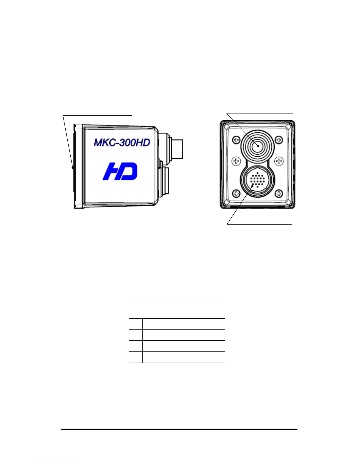
The MKC-300HD is authorized UL60601 Class I .
NOTE: This equipment has been tested and found to
comply with the limits for a Class A digital device,
pursuant to part 15 of the FCC Rules. These limits are
designed to provide reasonable protection against harmful
interference when the equipment is operated in a
commercial environment. This equipment generates, uses,
and can radiate radio frequency energy and, if not
installed and used in accordance with the instruction
manual, may cause harmful interference to radio
communication. Operation of this equipment in a
residential area is likely to cause harmful interference in
which case the user will be required to correct the
interference at his own expense.
Changes or modifications not expressly approved by the
party responsible for compliance could void the user's
authority to operate the equipment.
Please classify by the material, and dispose of them
according to the law and the ordinance etc. of the country
and the local government when you dispose of the main
body and materials for packing.
The MKC-300HD is not AP・APG equipment.
The BATTERY for BT1 in MKC-300HD, that should be
used same model as below when you need to
exchange it.
MODEL : CR2032
DN-27466

3
Guidance and manufacturer's declaration - electromagnetic emissions
The Model MKC-300HD is intended for use in the electromagnetic environment specified below. The
customer or the user of the Model MKC-300HD should assure that it is used in such an environment.
Emissions test Compliance Electromagnetic
The Model MKC-300HD uses RF energy only for its
internal function. Therefore, its RF emissions are very low
and are not likely to cause any interference in nearby
electronic equipment.
RF emissions CISPR 11 Group 1
RF emissions CISPR 11 Class A
Harmonic emissions
IEC61000-3-2 Class A
Voltage
fluctuations/flicker
emissions IEC61000-3-3
Complies
The Model MKC-300HD is suitable for use in all
establishments other than domestic and those directly
connected to the public low-voltage power supply network
that supplies buildings used for domestic purposes.
Immunity test IEC 60601 test level compliance level Electromagnetic environment
guidance
Electrostatic
discharge(ESD)
IEC61000-4-2
±6kV contact
±8kV air
±6kV contact
±8kV air
Floors should be wood, concrete
or ceramic tile. If floors are
covered with synthetic material,
the relative humidity should be
at least 30%.
Electrical fast
transient/burst
IEC61000-4-4
±2kV for power
supply lines
±1kV for input/output
lines
±2kV for power
supply lines
±1kV for input/output
lines
Main power quality should be
that of a typical commercial or
hospital environment.
Surge
IEC61000-4-5
±1kV differential
mode
±2kV common mode
±1kV differential
mode
±2kV common mode
Main power quality should be
that of a typical commercial or
hospital environment
Voltage dips, short
interruptions and
voltage variations on
power supply input
lines.
IEC61000-4-11
<5% Ut
(>95% dip In Ut)
for 0.5 cycle
40% Ut
(60% dip In Ut)
for 5 cycle
70% Ut
(30% dip In Ut)
for 25 cycle
<5% Ut
(>95% dip In Ut)
for 5 cycle
<5% Ut
(>95% dip In Ut)
for 0.5 cycle
40% Ut
(60% dip In Ut)
for 5 cycle
70% Ut
(30% dip In Ut)
for 25 cycle
<5% Ut
(>95% dip In Ut)
for 5 cycle
Main power quality should be
that of a typical commercial or
hospital environment. If the user
of the MODEL MKC-300HD
requires continued operation
during power mains
interruptions, It is recommended
that the MODEL MKC-300HD be
powered from an uninterruptible
power supply or battery.
Power frequency
(50/60 Hz)
magnetic field
IEC61000-4-8
3 A/m 3 A/m Power frequency magnetic fields
should be at characteristic of a
typical location In a typical
commercial or hospital
environment.
NOTE Ut is the a.c.mains voltage prior to application of the test level.
DN-27466

4
Guidance and manufacturer's declaration - electromagnetic emissions
The Model MKC-300HD is intended for use in the electromagnetic environment specified below. The
customer or the user of the Model MKC-300HD should assure that it is used in such an environment.
Immunity test IEC 60601 test level compliance level Electromagnetic environment guidance
Conducted RF
IEC61000-4-6
Radiated RF
IEC61000-4-3
3 Vrms
150 kHz to 80 MHz
3 V/m
80 MHz to 2.5 GHz
3 Vrms
3 V/m
Portable and mobile RF communications
should be used no closer to any part of
the MODELMKC-300HD, Including
cables, than the recommended
separation distance calculated from the
equation applicable to the frequency of
the transmitter.
Recommended separation distance
d=1.2√P
d=1.2√P 80~800 MHz
d=1.2√P 800 MHz~2.5 GHz
where P is the maximum output power
rating of the transmitter lnwatts (W)
according to the transmitter
manufacturer and d is the recommended
separation distance in meters(m)
Field strengths from fixed RF
transmitters, as determined by an
electromagnetic site survey, *ashould be
less than the compliance level In each
frequency range*b. Interference may
occur in the vicinity of equipment marked
with the following symbol:
NOTE 1 At 80 MHz and 800 MHz, the higher frequency range apply.
NOTE 2 These guidelines may not apply in all situations. Electromagnetic propagation Is affected by
absorption and reflection from structures, objects and people.
*a Field strengths from fixed transmitters, such as base stations for radio (cellular/cordless) telephones
and land mobile radios, amateur radio, AM and FM radio broadcast and TV broadcast cannot be
predicted theoretically with accuracy. To assess the electromagnetic environment due to fixed RF
transmitters, an electromagnetic site survey should be considered. If the measured field strength In
the location in which the MODEL MKC-300HD Is used exceeds the applicable RF compliance level
above, the MODEL MKC-300HD should be observed to verify normal operation. If abnormal
performance is observed, additional measures may be necessary, such as reorienting or relocating
the MODEL MKC-300HD.
*bOver the frequency range 150 kHz to 80 MHz, field strengths should be less than 3 V/m.
DN-27466

5
DN-27466
CONTENTS
2. Name and Function of Each Parts ............................................................................6
■Camera Head..............................................................................................................6
■Front Panel of Camera Control Unit (CCU) ............................................................. 5
■Rear Panel of Camera Control Unit (CCU)............................................................... 9
3. Operation.................................................................................................................. 11
■Connection ................................................................................................................ 11
■Electrical Connection ............................................................................................... 12
■Setting Auto White Balance.....................................................................................13
4. Menu Operation ....................................................................................................... 14
■Operation Method ....................................................................................................14
■Video Adjust.............................................................................................................. 15
■AE Mode ...................................................................................................................16
■DTL Set.....................................................................................................................17
■Video Setting ............................................................................................................18
■Auto Adjust ...............................................................................................................19
■Scene File.................................................................................................................. 20
■Foot Switch Mode..................................................................................................... 21
■Inverse ......................................................................................................................22
■STILL Setting........................................................................................................... 22
■Date/Time Adjust...................................................................................................... 23
■DVI Setting ............................................................................................................23
■Down Converter setting ...........................................................................................24
■Miscellaneous ...........................................................................................................24
■Version Info ...............................................................................................................25
5. Specification .............................................................................................................25
■Ratings......................................................................................................................25
■Performance.............................................................................................................. 26
■Functions ..................................................................................................................26
6. External Appearance................................................................................................28
■Camera Head Unit:mm............................................................................ 28
■CCU........................................................................................................................... 28

6
2.Name and Function of Each Parts
■Camera Head
Rear View
Side View
②Lens Connector
1/3” C-mount①
③Camera Connector
① 1/3” C-mount
Mount for connecting the lens and microscope adapter.
② Lens Connector
Used to connect the Iris cable of the special microscope adapter and 1/3” C-mount
lens.
Lens Connector Pin Assignment
(Connector Type: HR10A-7R-4S)
1 +12V
2 GND
3 IRIS
4 N.C
③ Camera Connector
Used to connect to the Camera connector of CCU with the Camera cable.
DN-27466

5
■Front Panel of Camera Control Unit (CCU)
○
1Power Switch ○
5Automatic Gain Control Switch
① Power Switch
To power on/off MKC-300HD. When this switch is turned on, the logo of "Ikegami"
lights up blue. Pressing the top of the switch turns on power, and pressing the bottom
of the switch turns off power. When this switch is turned on, the picture is output in the
state where power was last turned off. However, the state of still screen picture is not
○
16 Arrow Key
○
2Auto White Balance Switch
○
3Color Bar Switch ○
7Detail Enhancement Switch
○
8Freeze Picture Switch
○
4Electronic Shutter Switch
○
9Picture Save Switch
○
6Iris Control Switch
○
13 Video Level Indicator
○
12 Brightness Control Volume
○
11 Blue Paint Volume ○
15 SET Switch
○
10 Red Paint Volume ○
14 Menu Switch
○
17 USB connector
DN-27466

6
held.
② Auto White Balance Switch
To execute Auto White Balance. Use this switch, when the camera is not used for a
certain time, color balance is not proper, and the light source changes. To control the
white balance, project a white photographic object and adjust the iris just before
LEVEL INDICATOR lights up red. When AWB switch is pressed, "Auto White
Balance" appears on the monitoring screen to execute auto white balance. After
several seconds, "= OK =" appears on the screen, ending auto white balance.
When an auto iris lens or an iris control adjustable microscope adapter is used,
the iris will be set to an optimum condition automatically.
③ Color Bar Switch
Output an internal color bar signal of the camera to a color monitor. This color bar
signal can be used to control the brightness, contrast, etc. of the color monitor.
④ Electronic Shutter Switch
To keeps the video signal output level constant by controlling shutter speed
automatically. Automatic switching from 1/100 seconds to 1/10,000 seconds. When
this switch is used with ○
5Automatic Gain Control Switch, an optimum picture can be
output regardless of the brightness of an object.
⑤ Automatic Gain Control Switch
When shooting a dark scene from a bright scene, this function automatically
controls sensitivity setting inside the camera, thereby keeping the video signal
output level constant. It is possible to choose between increasing sensitivity by
6steps from up to +3
dB (1.5 times) and till up to +18dB (6 times) on the menu.
When this switch is used with ○
4Electronic Shutter Switch, an optimum picture
can be output regardless of the brightness of a photographic object.
⑥ Iris Control Switch
To switch the iris of the microscope adapter and lens to Auto (Auto iris).
⑦ Detail Enhancement Switch
The skin tone color is mainly enhanced.
DN-27466

7
⑧ Freeze Picture Switch
By pressing the switch, the video images can be captured as a still picture.
⑨ Picture Save Switch
Press the switch to acquire the still picture from the camera into USB storage
connected to 17USB connector. The picture quality is 1920x1080 pixels at Bitmap
format (non-compressed) or 1920x1080 pixels at JPEG format. The stored picture
quality can be adjusted on the menu.
⑩ Red Paint Volume
To finely control the red color on the video images.
⑪ Blue Paint Volume
To finely control the blue color on the video images
⑫ Brightness Control Volume
To finely control the brightness of the video images. It works as a control function
while ○
4Electronic Shutter and ○
5Automatic Gain Control are operative. When
using an auto iris adjustable microscope adapter or an auto iris lens, it works as a
fine control function, with ○
6Iris Control Switch turned on. It can be manually
controlled when this switch turned off.
⑬ Video Level Indicator
Indicate the video output level. When LED of the video level indicator lights up red, it
means that the video output signal level has exceeded 100%.
⑭ Menu Switch
To display the menu that the user can set as desired on the monitor.
Select an item you want to set with ○
16 Arrow key and define it with ○
14 Menu
Switch for menu items you can set.
Refer to “Menu Operation” (Page 15) for further detailed operations.
⑮ SET Switch
To define the item you want to set with the menu displayed, press this switch. Refer to
“Menu Operation” (Page 15) for further detailed operations.
DN-27466

8
⑯ Arrow Key
To select a scene file among 1, 2, 3 and Function. The scene file setting can be fixed
through the menu. When selecting an item you want to set on the menu, move cursor
by clicking Arrow Keys , and changing the contents of the item you want to set,
choose the value you have set by clicking Arrow Keys .
⑰ USB Connector
Used to connect the USB storage for saving a still picture.
DN-27466

9
■Rear Panel of Camera Control Unit (CCU)
○
5VBS Output Connector
○
6S-VIDEO Output Connector ○
8USB Connector
○
7SD RGB Output Connector
○
9DVI-D Output Connector
① Camera Connector
Connect the camera cable from the camera head.
② HD-SDI Output Connector
Output 2ch of HD-SDI signal.
Connect a Video Cable (Option) to a HD-SDI input interfaced monitor.
③ Genlock Input Connector
To use in phase synchronization with other systems. Connect a synchronized
signal from another system. Equivalent to Three-Phase Synchronization (HD) and
Two-Phase Synchronization (SD).
○
10 Foot Switch Connector
○
3Genlock Input Connector
○
1Camera Connector
○
4HD RGB Output Connector
○
2HD-SDI Output Connector
⑪Potential Equalization Terminal
DN-27466

10
④ HD RGB Output Connector
Output HD RGB video signal. YPbPr video signal output is also available by
changing the setting on the menu.
Refer to “Video Setting” (Page 19) for further detailed operations.
Connect a RGB Video Cable (Option) to a RGB input interfaced monitor.
⑤ VBS Output Connector (SD)
Output SD video signal.
Connect a Video Cable (Option) to a SD Video input interfaced monitor.
⑥ S-VIDEO Output Connector (SD)
Output Y/C video signal.
Connect a S-VIDEO Cable (Option) to a S-VIDEO input interfaced monitor.
⑦ SD RGB Output Connector
Output SD RGB video signal. YPbPr video signal output is also available by
changing the setting on the menu.
Refer to “Video Setting” (Page 19) for further detailed operations.
Connect a RGB Video Cable (Option) to a RGB input interfaced monitor.
⑧ USB Connector
Connect USB storage device.
⑨ DVI-D Output Connector
Connect a DVI-D Cable (Option) to a DVI-D input interfaced devices such as
monitor.
⑩ Foot Switch Connector
To
connect
the
FOOT
SW
cable
extension
from
the
foot
switch
(black) for a still picture
capturing.
⑪ Potential Equalization Terminal
This connector uses for potential equalization grounding which have one point of
protective earth.
DN-27466

11
3.Operation MKC-300HD
■Connection Camera Head
DVI interfaced equipment
DVD recorder
DVI-D cable
A
C outlet
RGB cable
Foot Switch
MKC-300HD CCU Rear Panel
S-VIDEO cable
Camera cable
Coaxial cable
Monitor
* Terminate the output from RGB OUT and VIDEO OUT at 75ohms on the receiver
side.
CAUTION for USB Connection
The USB output of this camera is provided to record
picture signals at JPEG or BMP format only into an
external USB storage device, and it has no function to
exchange the control signal from external equipment.
When making USB connection between this camera and a
USB storage device, the USB output may not operate
properly according to equipment.
For USB storage device of which operation has been
already confirmed, please contact our company.
DN-27466

12
■Electrical Connection
Turn on power supply to the monitor and other external equipment. Check that
CCU and the camera head are connected with a camera cable, and then turn on
power supply (POWER switch) of CCU.
When power to CCU is turned on, MKC-300HD
(CAMERA HEAD+CCU) is
initialized by the built-in computer. The pictures on the monitor are not stable
during this period. However it is not a failure.
When initialization is finished, the video image from the camera is output under
the same setting condition with the last use. (Note1)
* When moving the CCU, be sure to turn off the POWER switch, disconnect the
power plug and remove the connecting cable between equipment beforehand.
CAUTION Caution for Camera cable connection and disconnection
Turn off the power of MKC-300HD when you connect or
disconnect the camera cable. If the CCU is turned on, it may
cause the fault of MKC-300HD.
NOTE: Phenomenon on video image
MKC-300HD may happen following phenomenon on its video
image. It is not failure but it is because of employing CMOS
sensor
When its sensitivity gain is going up and/or when it is slow
shutter mode, it may appear high lighting dots. In case under
high temperature condition, it may be remarkable.
It may appear horizontal stripe pattern or flicker on a video
image under the fluorescent lighting. In this case, please use
manual electrical shutter of 1/100 (50Hz area) or 1/120 (60Hz
area). It will be reduce, but please note that it will not
disappear at all.
In case of fast moving object on a video image, it may appear
distortions.
Note1
When power is turned off in the state of still screen picture, that state will not be held
even if power is turned on again, and MKC-300HD is set to the normal shooting state.
DN-27466

13
■Setting Auto White Balance
Usually, MKC-300HD can be operated immediately after turning the power switch
on. Therefore, any other operations are unnecessary.
However, when using MKC-300HD for the first time, or when the light source has
been changed, Auto White Balance setting is required.
<Operation>
A
uto White Balance Switch
① Shoot a white photographic object on the screen largely. Set the picture level to
such a degree that the white photographic object is not excessively bright, and press
AWB button.
② “Auto White Balance” appears on the monitor screen. When auto white balance
is finished, “OK” appears.
Auto White Balance
Auto White Balance
= O K =
When the video level is low, "Too Dark" appears.
If Auto White Balance is "NG", check the video level etc. and then press
the white balance switch again.
DN-27466

14
4. Menu Operation
MKC-300HD has various useful and practical functions. The user can select and set
these functions on the menu. The basic operation is as follows.
■Operation Method
1. Pressing the ○
14 Menu switch (ref. page 5) on the front panel of CCU displays a
menu on the monitoring screen, on which various camera functions can be set.
▪▪▪MENU ▪▪▪
Video Adjust
AE Mode
DTL Set
Video Setting
MENU
Auto Adjust
Scene File
Foot Switch Mode
Inverse
STILL Setting
Date/Time Adjust
DVI Setting
Down Converter setting
Miscellaneous
Version Info
2. Select an item by Arrow Keys on the front panel of CCU, and press SET
switch to define the mode.
* Pressing Menu switch on the front panel of CCU while the menu screen is
displayed quits the menu screen.
SET
DN-27466

15
■Video Adjust
Used to adjust the level of black, red and blue of video picture.
Video Adjust
QUIT
Master Pedestal -5
Gain Offset Red 0
Blue 0
[Master Pedestal]Used to change the master pedestal value by
Arrow Keys . It is not used during ordinary
operation.
[Gain Offset Red]Used to change the level of red by Arrow Keys
switches. It has the same function as ○
10 Red
video volume (ref. page5) on the front panel of
CCU.
[Blue]Used to change the level of blue by Arrow Keys
switches. It has the same function as ○
11 Blue
video volume on the front panel of CCU.
DN-27466

16
■AE Mode
Used to adjust the electronic shutter and automatic sensitivity setting.
AE Mode
QUIT
Manual Shutter OFF
AE Level Set 0
AE Speed Middle
AE Sensitivity 40
Peak Ratio Set 0
Area Select Middle
AGC Max Gain 3dB
Normal Gain setting -3dB
Auto Shutter Limit 1/10000
[Manual Shutter]Usually, turn it to OFF. When using at a certain
electronic shutter speed, change it by Arrow
Keys switches.
[AE Level Set]Used to finely control brightness, when Manual
Shutter is turned off, and either
or
both
of ○
4
Electronic
S
hutter
S
witch (ref. page5)
and ○
5
Automatic Gain Control Switch on the Front
Panel of CCU are turned on. It has the same
function as ○
12 Brightness Control Volume on the
Front Panel of CCU.
[AE Speed]Used to select the response rate of the Electronic
Shutter and Automatic Gain Control from among
Middle, Fast and Slow.
[AE Sensitivity]To adjust the tolerance level ratio to the target
level according to the peak value of video signal
within the photometric area and the electronic
shutter.
[Peak Ratio Set]To change the type of photometry while the
Electronic Shutter and Automatic Gain Control
are operative. [+]direction:Peak value photometry.
[-]direction: Average value photometry.
DN-27466
Table of contents
Other Ikegami Color Camera manuals