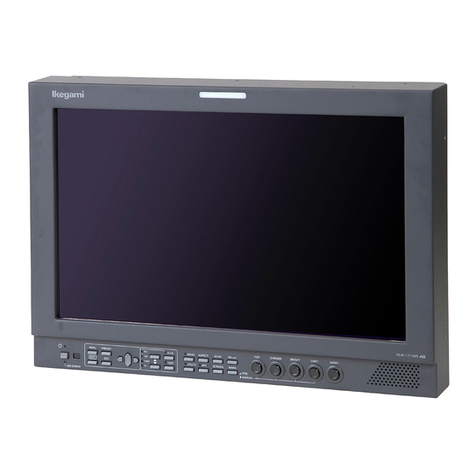
Ikegami HTM-1917R User manual

MODEL
HTM-1917R
HDTV/SDTV MULTI FORMAT
COLOR MONITOR
OPERATION MANUAL


SA 1966
SA 1965
CAUTION
RISK OF ELECTRIC SHOCK
DO NOT OPEN
CAUTION: TO REDUCE THE RISK OF
ELECTRIC SHOCK, DO NOT
REMOVE COVER (OR BACK).
NO USER-SERVICEABLE
PARTS INSIDE. REFER
SERVICING TO QUALIFIED
SERVICE PERSONNEL.
The lightning flash with arrowhead inside a triangle is intended to warn the user that
parts inside the product are dangerous and many cause electric hazards.
The exclamation mark inside a triangle is intended to inform users that important
operating and servicing instructions are provided with the equipment.
SA 1966
SA 1965
WARNING: FOR CONTINUED SAFETY, REPLACE SAFETY CRITICAL
COMPONENTS ONLY WITH MANUFACTURE’S RECOMMENDED
PARTS (REFER TO SERVICE LITERATURE).
WARNING: TO REDUCE THE RISK OF ELECTRIC SHOCK, DO NOT EXPOSE THIS
EQUIPMENT TO RAIN OR WATER.
INFORMATION TO USER FOR FCC
Warning
This equipment generates, uses and can radiated radio frequency
energy and if not installed and used in accordance with the instruction
manual. May cause interference to radio communications.
It has been tested as a Class A computing device and found to comply
within the limits for a Class A computing device in accordance with
the specifications in subpart J of Part 15 of FCC Rules, which are
designed to provide reasonable protection against such interference
when operated in a commercial environment.
Operation of this equipment in a residential area is likely to cause
interference in which case the user will be required at his own expense
to take whatever measures may be required to correct the interference.
Instructions for Disposal of Electric and Electronic Equipment in Private Household
Disposal of used Electric and Electronic Equipment
(Applicable in the European Union and other European countries with separate collection systems)
This symbol on the product, or in the related documents in the package, indicates that this product shall not
be treated as normal household waste. Instead, it should be taken to a proper applicable collection point or
depot for the recycling of electric and electronic equipment.
By ensuring this product is disposed of correctly, you will help prevent possible negative consequences for the
environment and human health, which could otherwise be caused by inappropriate waste handling of this product. The
recycling of materials will help to conserve natural resources.
For more detailed information about recycling of this product, please contact your local city authority, your household
waste disposal service or the place where you purchased the product.

IMPORTANT SAFETY INSTRUCTION
1. General
1) Read all instructions provided.
2) Save these instructions for future use.
3) Follow all warnings and instructions marked
on the television equipment.
4) Never insert objects of any kind into this
television monitor through cabinet slots as
they may come in contact with dangerous
voltage points or short out parts, resulting in
fire or electric hazards, Never spill liquid of
any kind on the television monitor.
5) Do not attempt to service this television
monitor yourself as operating or removing
covers many expose you to dangerous voltage
or other hazards, Refer all servicing to
qualified service personnel.
6) Do not use attachments not recommended by
the television equipment manufacturer as they
may result in the risk of fire, electric shock, or
injury to persons.
7) This television monitor has been preadjusted
to meet the respective broadcasting standard
signals. So, it cannot be used with the signals
of different broadcasting standards.
8) When keeping or transporting the unit for a
long time, pack it in the supplied carton or
equivalent.
2. Power supply
1) This television equipment should be operated
only from the type of power source indicated on
the marking label.
2) This television equipment is provided with a
three-wire grounding type plug with a third
(grounding) pin. This plug will only fit into a
grounding-type power outlet. This is a safety
feature. If you are unable to insert the plug
into the outlet, contact your electrician to
replace your obsolete outlet.
Do not defeat the safety purpose of the
grounding-type plug.
3) When connecting and disconnecting the
power cable, be sure to hold the plug.
4) Do not allow anything to rest on the power
cord. Do not place this television equipment
where the cord will be abused by persons
walking on it.
5) For added protection for this television
equipment during a lightning storm, or when
it is left unattended and unused for long
periods of time, unplug it from the wall outlet.
This will prevent damage to the equipment
due to lightning and power-line surges.
6) Do not overload wall outlets and extension
cords as this can result in fire or electric shock.
3. Usage and location
1) Do not use this television equipment near
water - for example, near a bath tub,
kitchen sink, or laundry tub, in a wet basement,
or near a swimming pool, or the like.
2) Do not place this television equipment on an
unstable cart, stand, or table. The television
equipment may fall, causing serious injury to
children and adults, and serious damage to the
equipment. Use only with a cart or stand
recommended by the manufacture, or sold
with the television equipment. Wall or shelf
mounting should follow the manufacture’s
instructions, and should use a mounting kit
approved by the manufacture.
Television equipment and cart combination
should be moved with care. Quick stops,
excessive force, and uneven
surfaces may cause the
equipment and cart
combination to overturn.

3) Slots and openings in the cabinet and the back
or bottom are provided for vitiation, and to
ensure reliable operation of the monitor and
to protect it from overheating, these openings
should never be blocked or covered. The openings
should never be blocked by placing the
television equipment on a bed, sofa, rug, or
other similar surface. (This television
equipment should never be placed near or
over a radiator or heat register.)
This television equipment monitor should not
be placed in a built-in installation such as a
bookcase unless proper ventilation is
provided.
4) Avoid operating or placing (keeping) in a hot
(+40ºC or over) or cold (less than 0ºC), high
vibration, or dusty place. Avoid operating or
placing (keeping) in a place exposed to direct
sunlight, otherwise the CRT surface may
deteriorate.
5) If an image of extremely high brightness is
displayed on the screen for a long time, the
CRT may get burned in.
4. Cleaning
1) Unplug this television equipment from the
wall outlet before cleaning. Do not use liquid
cleaners or aerosol cleaners. Use a damp cloth
for cleaning.
2) Do not use thinner or benzine for cleaning.
Otherwise, the cabinet may deform or the
paint may peel away.
IMPORTANT SAFETY INSTRUCTION
5. Repair
1) Unplug this television monitor from the wall
outlet and refer servicing to qualified service
personnel under the following conditions:
a. When the power cord or plug is damaged
or frayed.
b. If liquid has been spilled into the
television.
c. If the television monitor has been exposed
to rain or water.
d. If the television does not operate normally
by following the operating instructions.
Adjust only those controls that are
covered by the operating instructions as
improper adjustment of other controls may
result in damage and will often require
extensive work by a qualified technician
to restore the television monitor to normal
operation.
e. If the television monitor has been dropped
or the cabinet has been damaged.
f. When the monitor exhibits a distinct
change in performance - this indicates a
need for service.
2) When replacement parts are required, be sure
the service technician has used replacement
parts specified by the manufacture that have
the same characteristics as the original part.
Unauthorized substitutions may result in fire.
Electric shock, or injury to persons.
3) Upon completion of any service or repairs to
this monitor, ask the service technician to
perform routine safety checks to determine
that the television is in safe operating
condition.
4) For repair service, contact Ikegami’s
authorized sales representative or Ikegami
service desk directly.

PRECAUTIONS FOR OPERATIONS
1) Never let this unit fall or subject it to strong
shock.
2) Do not remove the cabinet unless necessary.
High-voltage parts are contained in the
cabinet and they are very dangerous if you
touch then. Only qualified service engineers
are allowed to adjust the internal parts of the
cabinet.
3) This color monitor has been adjusted to
signals conforming to each broadcasting
standard.
It cannot be used for signals of different
broadcasting standards.
Be sure to operate the color monitor within
the voltage range marked on its back.
4) If cabinet or screen is dirty, wipe with soft
cloth. At this time, avoid using benzine or
thinner.
Otherwise, the paint may peel away.
5) Note that, if video signals with high
luminance are monitored on the CRT over a
long period of time, the CRT may burn in the
image.
6) Avoid using or storing this unit in the
following places:
•Hot (+40ºC or more) or cold (0ºC or less)
places.
Especially where this unit may be exposed
to the direct rays of the sun; the cabinet
may deform and the fluorescent screen of
the CRT may deteriorate.
•Humid and dusty places.
•Places where there is considerable
vibration.
• Places exposed to rain or water.
•When storing or transporting this unit, pack it
in the supplied carton or equivalent.
7) If no image can be monitored even after
performing user adjustment or the unit
appears faulty, do not dismantle this unit by
yourself. In such cases, contact the Ikegami
service desk.
8) Should this unit fail within one year after
delivery, it will be repaired free of charge
unless the malfunction was caused by
mishandling or misuse of the user.
However, the fuses are not covered
by the warranty.
9) The specifications and appearance of this unit
may be subject to change for further
improvement without prior notice.

To ensure safe use of this monitor, read this manual carefully, paying particular attention to
the following items.
1. Do not use any power supply other than the regulation AC power.
2. Do not subjecting the monitor to strong impact.
Otherwise, it will result not only in malfunction, but explosion of the CRT as well.
3. Avoid use and storage in the following places.
*Locations which do not meet the designated ambient temperature
installing the monitor near equipment generating heat or in cabinets with closed vents
causes the internal temperature of the monitor rise, which not only reduces the life of the
electrical parts but also causes malfunction.
*Locations with rain, snow, or excess humidity
Locationing the monitor in the above conditions will cause malfunction.
*Strong magnetic fields
4. Avoid exposing the CRT to sunlight
Subjecting the CRT to direct sunlight for a long period of time deteriorates the florescent
faces of the CRT. So avoid use outdoors.
5. Avoid exposing to high luminance fixed image for long periods of time
Take care as this will cause burning of the CRT.
Also avoid displaying remote numbers in the remote entry state (remote numbers are displayed
when the wireless remote controller is used) for long periods of time. When not using the
wireless controller, set the remote number displayed on the screen to OFF.
Guarantee
Malfunctions occurring in normal use within one year from the date of purchase will be repaired
free of charge. This does not apply to the fuses.
If no image is displayed after user adjustment or if malfunction is suspected, contact your nearest
Ikegami dealer.
Accessories
This monitor is provided with the following accessories.
Check that none is missing.
1. Operation manual
2. AC cable
3. Remote connector
* Specifications and external dimensions are subject to change without prior notice.
Precautions Upon Use

CONTENTS
IMPORTANT SAFETY INSTRUCTIONS
Precautions Upon Use
1. Outline .......................................................... 1
1-1 Outline ................................................... 1
1-2 Features ................................................ 1
2. General Specifications ................................ 3
2-1 Common Specifications ..................... 3
2-1-1 General ............................................... 3
2-1-2 Video Signals System ......................... 3
2-1-3 Brightness and Contrast ................... 3
2-1-4 Deflection/Sync System ..................... 3
2-1-5 Functions ............................................ 3
2-1-6 Memory ............................................... 4
2-1-7 Applicable Standards ......................... 4
2-2 Individual Specifications .................. 4
2-2-1 YPbPr/RGB input module ................. 4
2-2-2 Multi-format SDI input module ........ 5
2-2-3 SD-SDI input module ........................ 5
2-2-4 Decoder input module ........................ 6
2-2-5 Audio level meter module .................. 6
2-3 Options .................................................. 6
2-4 External View ...................................... 7
2-4-1 HTM-1917R ........................................ 7
2-4-2 HTM-1917R(with DAM-504/508) ...... 8
3. Installation .................................................... 9
3-1 External connection ........................... 9
3-1-1 Standard module ................................ 9
3-1-2 Multi-format SDI input module ........ 10
3-1-3 SD-SDI input module ........................ 11
3-1-4 NTSC/PAL-B decoder input module ... 11
3-2 Parallel Remote Connection ............ 12
3-2-1 Pin function ........................................ 12
3-2-2 Connectors used ................................. 12
4. User Adjustment .......................................... 13
4-1 Power Supply ...................................... 13
4-2
Names and Functions of Front Left Panel Parts ...
13
4-3
Names and Functions of Front Controller Parts ...
14
4-3-1
Names and functions of front panel parts .......
14
4-3-2
Names and Functions of Drawer Panel Controls ..
17
4-4
Storing and Changing Data in the Memory ..
21
4-4-1
Storing and changing the PRESET data .
21
4-4-2
Changing and storing the FILE DATA ....
22
4-5 Types of Markers ................................. 23
4-6 Adjustment Procedure ...................... 24
4-6-1 Adjusting the brightness ................... 24
4-6-2 Adjusting the contrast ....................... 24
4-6-3 Adjusting the white balance .............. 24
4-6-4 Adjusting the color balance ............... 26
4-6-5 Adjusting the rotation ....................... 26
4-6-6 Adjusting the screen center ............... 27
4-6-7 Adjusting the screen distortion ......... 28
4-6-8 Adjusting the screen size ................... 28
4-7 MENU Functions ................................. 30
4-7-1 List of MENU ..................................... 30
4-7-2 Flow of MENU Operations ................ 31
4-7-3 Description of MENU 1 Functions .... 32
4-7-4 Description of MENU 2 Functions .... 32
4-7-5 Description of MENU 3 Functions .... 33
4-7-6 Description of MENU 4 Functions .... 34
4-7-7 Description of MENU 5 Functions .... 34
4-7-8 Description of MENU 6 Functions .... 35
4-7-9 Description of MENU 7 Functions .... 35
4-8
Messages Displayed on the Screen .........
36
5. Installation of Options ................................. 37
5-1 Option Module ..................................... 37
5-2 Rack Mount Adapter .......................... 38
5-3 Remote Controller .............................. 39
5-1-1
RCT-30A Infrared Remote Controller ......
39
5-1-2
SRC-301Z Serial Remote Controller ........
40
6. Memo ........................................................... 41

1
1. Outline
1-1. Outline
This 19-inch type HDTV/SDTV multi-format color
monitor has been designed taking into consideration
compatibility with all HDTV formats as, well as, the
combined use of HDTV and SDTV formats, and also
active use in all kinds of spaces such as sub-control
rooms, editing rooms, monitor wall, transmission
control desks, OB Van, etc.
This monitor is compatible with HDTV:1080i/
1035i/720p, SDTV:480i and NTSC/PAL-B and multi
TV formats (including options) to deal with diverse
broadcasting formats and system needs. It can also
be connected easily with current analog component
and composite inputs, as well as, HD/SD serial digi-
tal inputs.
The monitor adopts a plug-in module method
which enables the system to be changed or expanded
by simply plugging in the module without opening
the cover. This professional color monitor also takes
into account ease of expendability and maintenance.
Newly developed SDI module supports multi-for-
mat inputs. In addition, an optional module sup-
porting embedded audio is also available.
Embedded audio incorporates versatile functions
such as analog or AES/EBU digital outputs and au-
dio level meter display, making the monitor highly
cost effective due to its capability of simultaneous
video and audio monitoring with a single unit.
1-2. Features
Multi-format
The monitor supports the following broadcasting formats.
•480i/59.94: ITU-601
•575i/50: ITU-601
•1035i/60,59,94: SMPTE240M, BTA S-001B
•1080i/60,59,94: SMPTE274M
•1080i/50: SMPTE274M(Option)
•1080p/24sF,23.98sF: SMPTE RP211(Option)
•720p/60, 59.94: SMPTE296M
•480p/60, 59.94: SMPTE293M (Option)
Multi-format SDI
The Multi-format SDI module (DKM-511B) is ca-
pable of accepting both HD-SDI and SD-SDI (4:2:2)
signals in the same input terminal.
The monitor automatically identifies HD-SDI or
SD-SDI (4:2:2) signal input for display in appropri-
ate format.
Compatibility with embedded audio output
Equipped with demultiplexer circuit, the optional
multi-format SDI module (AV or AVD type), which sup-
ports embedded audio output, can extract and output
the audio signal multiplexed with HD-SDI signal or
SD-SDI (4:2:2) signal.
The module is available in two types in terms of its
audio output, AV type producing 2-channel analog out-
put (output channel to be set in MENU) and AVD type
producing AES/EBU digital 8-channel output.
Embedded audio level meter
DAM-504 and DAM-508 modules (optional) are the
audio level meters that work with the embedded au-
dio to monitor 4-channel or 8-channel audio signal
multiplexed with SDI signal.
Easily visible LED meter installed in the escutch-
eon will not obstruct video monitoring. Integrated
with the monitor, the meter requires no extra space.
Remote control functions
The monitor can be remote-controlled with the use
of three remote control functions. Depending on the
place of installation and type of operation, a parallel,
infrared, or serial remote controller can be used.
In addition to the conventional parallel remote con-
trol, the monitor also comes equipped as standard with
serial remote input interface which enables remote
control with just one BNC coaxial cable.
By connecting various monitors (17/18/20/30/80/90/
HTM/HLM series monitors) by the loop-through
method, up to 99 monitors can be remote-controlled
individually, using the optional remote controller SRC-
301Z.
The infrared wireless remote controller RCT-30A is
also available as an option.
Digital control
Digital data is processed in 10-bit. The rotary en-
coder enables easy adjustment and changes to the
data.
The screen size and position, as well as, side pin
compensation can also be controlled remotely, thus al-
lowing flexible compatibility with various signal for-
mats.
Memory of 4 different of color temperatures
As the monitor is able to memorize other color tem-
peratures in addition to the D93/D65 color tempera-
tures set as default, the optimum white balance can
be set promptly, as well as, easily according to the in-
put image conditions and purpose of use.
HTM-1917R Multi-Format Color MonitorHTM-1917R Multi-Format Color Monitor

2
BFS (Beam feedback system)
By adopting a BFS circuit for detecting CRT cath-
ode current, stable black balance can be obtained
for a long period of time even when the CRT emis-
sion changes.
Built-in 3-line comb filter (NTSC)
With NTSC analog composite signal input, the de-
coder module which includes a 3-line comb filter cir-
cuit realizes a high resolution picture by the digital
delay method, using 8 fsc clock.
The Faroudja™ format 3-line comb filter used for
Y/C separation reproduces high picture quality im-
ages with minimum cross color and cross luminance.
* Requires the optional NTSC decoder module DE-
801.
Rich variety of internal test signals
The monitor is equipped with a variety of useful
test signals for adjustments such as crosshatch, flat
field (50%), window (100%), character, and staircase
waveform with pluge.
The format of the test signal can also be selected
from HDTV:1080i/1035i/720p, SDTV:480i/575i by
MENU settings.
Built-in markers
4:3 markers can be displayed on 16:9 images.
80%, 88%, 90%, 93%, 100% and other markers can
be displayed for the 4:3/16:9 aspects in NTSC.
Shadow function
While displaying pictures with an aspect ratio of 16:9,
the monitor displays 4:3, 13:9, and 14:9 image areas
and creates a shadow (the shadow contrast is set up to
about 40%) at the other image portion. This monitor is
capable of viewing 4:3, 13:9, and 14:9 images
simultaneously while monitoring 16:9 images.
As this shadow function can be turned on and off by
remote control, prompt switching is realized.
Degauss timer function
The degauss timer function sets the timer so that
auto degauss operations are performed automati-
cally about 4 seconds after the power is turned ON.
The timer can be set for each monitor at intervals
of 0.5 seconds from 0 to 4.5 seconds.
This minimizes the rush current flowing when the
power of a system comprised of multiple monitors
is turned on at once.
Structure with enhanced maintenance and
expendability
The signal processing module, including optional
modules, are of the plug-in type which can be easily
disconnected and connected from the back without the
need to remove any cover, thus allowing easy mainte-
nance.
Besides the DKM-511B multi-format SDI module
and analog component signal (YPbPr) module, optional
modules, can be added for expansion.
Use of high performance in-line gun CRT
A high performance in-line gun CRT of 0.25mm dot
mask pitch is adopted to produce fine images with re-
duced reflection of external light.
A black matrix screen realizes images of high con-
trast with enhanced black purity.
Luminance compensation function by
image size
In the case of the CRT monitor, when the image
size is reduced from normal to under-scan or from 4:3
to 16:9 scan image size, the current density increases
to cause a change of luminance. This monitor per-
forms luminance compensation so that the luminance
remains constant even when any of the four image
sizes is changed.
HD 4:3 SCAN function
This function enlarges 4:3 image area only and dis-
plays it in full screen (aspect ratio 4:3) during the
HDTV mode, thus allowing real-time monitoring of
the image that would be obtained after down-convert-
ing to 4:3 aspect ratio of SDTV. During the HD 4:3
SCAN, the size of the 4:3 image area is magnified to
the size comparable to the size of 24-inch 16:9 CRT
screen.
High voltage regulation circuit
High voltage regulation circuit controls the pulse
for each scan line, thus realizing the high voltage sta-
bility of ±0.5%. This regulation circuit ensures quicker
response and minimal distortion in high luminance,
resulting in an image of high stability.
Auto setup function
Use of the auto setup probe ASP-100 (option) (under
development) enables automatic adjustment of the color
temperature easily.
When the operator sets the desired color tempera-
ture to the monitor, any number of monitors can be
automatically adjusted to this color temperature.
* The ASP-80 is also applicable.

3
2. General Specifications
2-1. Common Specifications
2-1-1 General
(1) Power supply:
AC single phase, 50/60 Hz
Within 100V area: 100V-120V ±10%
Within 200V area: 200V-240V ±10%
(2) Power consumption:
Max. 240W (with full options)
(3) Ambient temperature:
0ºC to +40ºC
(4) Humidity:
Below 90% (No condensation)
(5) Dimensions and weight:
450(W) x 399(H) x 515(D)mm, Approx. 37kg
(6) Standard accessories:
Power cable, remote connector, operation manual
x 1 each
(7) Operation: Continuous
(8) X-ray: Less than 0.1mR/H
(Anywhere 50mm or remoter from
the monitor)
2-1-2 Video Signals System
(1) Frequency response:
When inputting YPbPr
a) HDTV 60Hz~25MHz:+1dB/-3dB
More than 25MHz:Descending response
b) SDTV 60Hz~25MHz:+1dB/-3dB
More than 10MHz:Descending response
(2) Sag: Within 5%
(3) Black level stability:
For 10% to 90% APL changes: Within 1%
(4) Aperture correction amount:
Variable +6dB or more at the frequency below
a) HDTV 10MHz ±25MHz
b) SDTV 4MHz...*
* SDTV mounting the optional decoder module
(NTSC: DE-801, NTSC/PAL: DE-811) is compatible
with analog/digital composite signal only.
(5) Noise
Sync noise: More than -46dB
Hum noise: More than -50dB
Others: More than -50dB
2-1-3 Brightness and Contrast
(1) CRT
Dot trio pitch: 0.25mm
(2) Horizontal resolution
More than 900 lines (480i/575i/1080i) with
YPbPr input and 120 cd/m2in screen center
(3) Preset contrast
More than 120 cd/m2 (Factory setting)
(4) Maximum luminance
a) SDTV (4:3) : 170 cd/m2 (typ)
b) HDTV (16:9) : 240 cd/m2 (typ)
(100% window signal input, brightness: PRESET, contrast: MAX)
2-1-4 Deflection/Sync System
(1) 16:9 display size
a) NORMAL: 16:9 size within effective CRT
screen frame
b) UNDER: 350(W) x 197(H)mm
(2) Deflection
a) SDTV
NORMAL SCAN: (4:3/16:9)
UNDER SCAN: (4:3/16:9)
b) HDTV
NORMAL SCAN: (16:9)
UNDER SCAN: (16:9)
HD 4:3 SCAN: (Zoom for 4:3 area)
(3) Deflection distortion
Within ±2% of screen height (Deflection linearity
and raster distortion)
(4) Sync stability
Monitor sync keeps stable under the following input
conditions:
Internal sync: ±6dB of rated video input level
External sync:
External sync input level 0.3 to 6Vp-p
(5) High voltage
Generated voltage: 26kV ±1kV
High voltage fluctuation:
Within ±0.5% (150µA reference)
Beam current range within 0 to 600µA
(6) Convergence
Inside the center circle of screen height diameter:
Within 0.3mm
The rest of the screen area: Within 0.4mm
2-1-5 Functions
(1) Marker function
a) Center marker: Set to ON/OFF using MENU settings
b) Safe title:
The following markers are displayed according to
the aspect (4:3/16:9).
( ) indicates the aspect when markers are displayed.
Types
①80%+100% (4:3/16:9)
②88%+100% (4:3/16:9)
③90%+100% (4:3/16:9)
④93%+100% (4:3/16:9)
⑤5 divided crosshatch (4:3/16:9)
⑥10 divided crosshatch (4:3/16:9)
⑦Cross (4:3/16:9)
⑧14:9 marker (16:9)
⑨13:9 marker (16:9)
⑩4:3 marker (16:9)
⑪4:3 marker + 80% (4:3) marker (16:9)

4
(2) Shadow function
The following shadow is created in the 16:9 mode.
Types
①14:9 marker + 14:9 shadow
②13:9 marker + 13:9 shadow
③4:3marker + 4:3 shadow
④4:3 marker + 80% (4:3) marker + 4:3shadow
⑤14:9/13:9/4:3Shadow only
(3) Auto setup
The white balance can automatically be adjusted
using the auto setup probe ASP-100 (option) (under
development).
(4) Remote control
a) Parallel remote control channel
COMPOSITE/AUX/HD-SDI/SD-SDI, YPbPr/RGB,
COLOR/MONO, SYNC INT/EXT, 4:3/16:9,
4:3 MARKER ON/OFF, 4:3 SHADOW ON/OFF,
R/G.TALLY ON/OFF
b) Serial remote control
The input interface is equipped as standard and is
capable of controlling most of the monitor functions.
The controller SRC-301Z is optional.
c) Infrared remote control
The infrared remote controller RCT-30A is optional.
(5) Internal test signal
The format can be switched by MENU settings.
Types
①Crosshatch
②50% flat field
③100% window
④Characters
⑤Staircase waves with pluge signal
(6) Beam feedback system (BFS)
(7) Menu assist
•Input signal format setting
•RGB/YPbPr switching setting
•Test signal format setting
•Marker center cross display ON/OFF setting
•Marker color setting
•Remote ID setting
•Degauss timer setting
•%display of preset data
•Password setting
•Auto setup setting
•Embedded audio related setting
2-1-6 Memory
(1) Memory type
ROM: 64KB programmable ROM
RAM: 32KB static RAM
(2) Battery backup
Memory backup time: 10 years or longer
Battery: BR2330-1HF lithium battery
2-1-7 Applicable Standards
(1) Safety standards: Conforms to UL1950
(2)
Electromagnetic interference:
FCC Class-A
(3) X-ray radiation: DHHS
2-2. Individual Specifications
* DKM-511B multi-format SDI 2-input module and
YPbPr/RGB 1-input module are equipped as standard.
2-2-1 YPbPr/RGB input module
1-input module (Standard)
Dual component module
(Optional for YPbPr/RGB 1-input expansion)
(1) Input/output terminal
a) YPbPr/RGB: 1-input module (Standard)
YPbPr/RGB: BNC 1 line (Loop through)
Sync signal input: BNC 1 line (Loop through)
b) DCH-501
YPbPr/RGB: BNC 1 line (Loop through)
(2) Input signal format (YPbPr/RGB)
a) SDTV
•480i/59.94
•575i/50
•480p/59.94 (option)
b) HDTV
•1035i/60,59.94
•1080i/60,59.94
•1080i/50 (option)
•1080p/24sF, 23.98sF (option)
•720p/59.94, 60
•720p/50 (option)
(3) Input level
a) HDTV (BTA S-001B)
•Y, G, B, R input V: 700mVp-p Positive polarity
S: ±300mVp-p
•Pb, Pr input V: ±350mVp-p Positive polarity
•Sync input: ±300mVp-p
b) SDTV (SMPTE/EBU N10)
•RGB input VS: 1.0Vp-p Positive polarity
V: 0.7Vp-p Positive polarity
When all or none of R, G and B have sync signals,
and when only G has sync signal.
•YPbPr input
Y signal WHITE (100%):700mVp-p
SET UP: 0mVp-p
SYNC: 300mVp-p
•PbPr signal: 525mVp-p
(100/0/75/0 COLOR BAR)
•Sync input:
0.3-6Vp-p Negative polarity
(4) Input impedance
High impedance bridge connection or 75Ωtermi
nation
(75Ωtermination plug is optional.)
(5) Return loss
More than 46dB (10MHz)

5
2-2-2 Multi-format SDI input module
•DKM-511B Multi-format SDI module (Standards)
•DKM-511A Multi-format SDI module
Equipped with high performance x/sin x correc-
tion type video signal post-filter
•DKM-511AAV/BAV
(Multi-format SDI module supporting embedded
analog audio output)
•DKM511AAVD/BAVD
(Multi-format SDI module supporting embedded
AES/EBU audio output)
Video section
(1) Input/output terminal
Input: BNC 2 lines
Output: BNC 1 line (Active loop through for only
one line selected)
(2) Input signal format (HD/SD auto detection)
a) HD-SDI
•1035i/60,59.94
•1080i/60,59.94
•1080i/50
(When supported by the monitor)
•1080p/24sF, 23.98sF
(When supported by the monitor)
•720p/60,59.94
•720p/50
(When supported by the monitor)
b) SD-SDI(4:2:2)
•480i/59.94
•575i/50
(3) Input level rating: 800mVp-p±10%
(4) Transmission speed
a) HD-SDI: 1.485Gb/s
b) SD-SDI(4:2:2): 270Mb/s
(5) Quantization bit rate: 10 bits
(6) Input/output impedance:75Ω
(7) Return loss: More than 15dB(~742.5MHz)
More than 10dB(742.25~1485MHz)
(8) Transmission distance:
Over 100m (5CFB, 1.485Gb/s)
Audio section (AV / AVD type)
Common specifications for embedded audio
(1) Compatible embedded audio input formats
SMPTE272M: 480i/59,94(4:2:2)
575i/50(4:2:2)
SMPTE299M: 1035i/60,59,94
1080i/60,59,94
1080i/50
1080p/24sF, 23.98sF
720p/60,59,94
720p/50
(2) Format switching: Auto switching
(3) Sampling frequency: 48kHz (Synchronized
with video clock)
Analog audio output (AV type)
* Analog audio level 0dbs 0.775Vrms
(1) Output terminal:
XLR-5-32 type (Canon 5-pin male)
(2) Line output: Analog audio 2-channel
Active (no-transformer) balanced
output type
(3) Rated output level:
+4dBs * Load impedance 10kΩ
(At –20dBFS digital audio level)
(4) Max. Output level:
+24dBs * Load impedance 10kΩ
(At 0dBFS digital audio level)
(5) Output impedance: 50Ω
(6) Min. Load impedance: 600Ω
(7) Quantization bit rate: 24 bits/ch
(8) Emphasis:
50/15µs digital emphasis
(Auto detection)
(9) Frequency response: 20~20KHz±1dB
(10)S/N ratio: More than 80dB
(11)Dynamic range: More than 80dB
(12)Crosstalk: More than 60dB
(1kHz, Max. Output)
(13)Harmonic distortion: Less than 0.1%
(Rated output)
AES/EBU output (AVD type)
* Digital audio level 0dBFS, full bit in full scale
(1) Output connector:
BNC (Paired channel) 4 lines
(2) Output standards:
AES/EBU standards (for monitor)
(3) Output impedance: 75Ω
2-2-3 SD-SDI input module (Option)
•DK-801A (4:2:2 digital component module)
* Not supporting embedded audio
(1) Input/output terminal:
BNC 2 lines (Active loop through)
* The module can be preset to produce output signal
corresponding to the channel selected on the monitor.
(2) Input signal format:
4:2:2 digital component signal (480i/59.94, 575i/50)
(3) Input/output level:
Rated level: 800mVp-p±10% (75Ωtermination
for output level)
Scrambled NRZI system
(4) Transmission speed: 270Mb/s
(5) Quantization bit rate: 10 bits
(6) Input/output impedance: 75Ω
(7) Return loss: More than 15dB

6
2-2-4 Decoder input module (Option)
•DE-801 NTSC 3-line comb decoder module
•DE-811 NTSC/PAL-B comb decoder module
(1)
Input/output terminal: BNC 3 lines (Loop through)
(2) Signal format: DE-801 : NTSC composite signal
DE-811 : NTSC/PAL-B composite
signal
(3) Input level:
VS:1.0Vp-p Positive polarity
V:0.7Vp-p Positive polarity
(4) Input impedance:
High impedance bridge connection or 75 termination
(75Ωtermination plug is optional.)
(5) Return loss: More than 46dB (10MHz)
2-2-5 Audio level meter module (Option)
•DAM-504 4ch Embedded audio level meter
•DAM-508 8ch Embedded audio level meter
* DAM-504/508 requires DKM-511 *AV/*AVD.
(1) Compatible embedded audio input formats
SMPTE272M: 480i/59.94(4:2:2)
575i/50(4:2:2)
SMPTE299M: 1035i/60,59.94
1080i/60,59.94
1080i/50
1080p/24sF, 23.98sF
720p/60,59.94
(2) Format switching: Auto switching
(3) Reference level: -20dBFS
(4) Number of channels: DAM-504 : 4 channels
DAM-508 : 8 channels
(5) Display segment: 13 segments
(6) Display device: -∞~-25dB : Green LED
-20~0dB : Amber LED
2-3. Options
(1) DKM-511A
Equipped with a high-performance post-filter to
make x/sin x corrections on the two-input module
HDTV video signal of the Multi-SDI (HD-SDI/4:2:2).
(2) DKM-511AAV/BAV
Multi-format SDI module supporting embedded
analog audio output
(3) DKM-511AAVD/BAVD
Multi-format SDI module supporting embedded
AES/EBU audio output
(4) DAM-504
4-channel embedded audio level meter
(DKM-511* AV/AVD is required.)
(5) DAM-508
8-channel embedded audio level meter
(DKM-511* AV/AVD is required.)
(6) DK-801A 4:2:2 degital component module
(7) DE-801 NTSC 3-line comb decoder module
(8) DE-811 NTSC/PAL-Bgeneral-purpose
decoder module
(9) SRC-301Z
Serial remote controller
By connecting various monitors by the loop-
through method, up to 99 types of monitors can
be remote-controlled.
(10) RCT-30A Infrared remote controller
(11) ASP-100
Auto setup probe (under development)
Used for automatic color temperature adjustment
(12) EX-801A Extender board for adjustment
(13) MK-1905
16:9 mask
16:9 mask easily detachable from HTM-1917R
escutcheon
(14) RS-2020/S
19/20-inch rack mount adapter
RS-2020S has a sliding rail.
Notes:
Two or more DKM modules cannot be installed together.
Loading of DAM-504/508 is possible at the time of DKM-511*AV/*AVD type loading of combination 5-10.
DAM-504/508 is factory-optional.
Module
Slot width
No. of inputs
No. of outputs
Combination
1
Combination
2
Combination
3
Combination
4
Combination
5
Combination
6
Combination
7
Combination
8
Combination
9
Combination
10
DKM-511
1
MultiI-SDI x2
MultiI-SDI x1
DKM-511 AV
2
Multi-SDI x2
Multi-SDI x1
Embe. Analog
Audio x2ch
DKM-511 AVD
2
Multi-SDI x2
Multi-SD x1
Embe. AES/
EBU Audio x8ch
DK-801A
1
4:2:2 x2
4:2:2 x2
DE-801
1
NTSC x3
NTSC x3
DE-811
1
NTSC/PAL-B x3
NTSC/PAL-B x3
DCH-501
1
RGB/YPbPr x1
(1-input expansion)
RGB/YPbPr x1
(Any one of them)
(Any one of them)
(Any one of them)
(Any one of them)
(Any one of them)
(Any one of them)
Table 2-3. All combinations of optional slots

7
2-4. External View
(1) HTM-1917R
YPbPr/GBR
REMOTE HD/4 : 2 : 2 SDI
SD/
4 : 2 : 2 NTSC
SERIAL
POWER DEGAUSS
MONO
PUSH
KXT
STNC
DIGI
2nd
SLOT
YPbPr/RGB
SPLIT
COMB
APT
MARK R G B
ASPECT SCAN
SCREENS
PRESET
MANUAL
HUE CHROMA
HTM-1917R
COLOR MONITOR
BRIGHT CONT
1
2
3
DELAY
TEST
A
B
C
WARNING
OVER LOAD
NO BURST
PARALLEL
FUSE
6.25A250V
AC IN
AC100-120V
AC200-240V
MAIN
POWER
FUSE
625A250V
AC IN
AC100-120V
AC200-240V
MAIN
POWER
CH A
CH B CH A
CH 2/1
CH 3/4
CH 5/6
CH 7/8
MONITOR OUT
AIS / EBU OUT
DKM501AVD
CH B
CH A
MONITOR
OUT
()
CH B
Y/G
Pb/B
CH C Pr/R
SYNC
CH A
PAR ALLEL
INPUT SELECT
FILE
390±1.535±1.5390±1.5
222±120
399±1
ø20
ø22
515±1.5
449.6±1
(27)
Optionmodule

8
(2) HTM-1917R (with DAM-504/508)
YPbPr/GBR
REMOTE HD/4 : 2 : 2 SDI
SD/
4 : 2 : 2 NTSC
SERIAL
POWER DEGAUSS
MONO
PUSH
KXT
STNC
DIGI
2nd
SLOT
YPbPr/RGB
SPLIT
COMB
APT
MARK R G B
ASPECT SCAN
SCREENS
PRESET
MANUAL
HUE CHROMA
HTM-1917R
COLOR MONITOR
BRIGHT CONT
1
2
3
DELAY
TEST
A
B
C
WARNING
OVER LOAD
NO BURST
PARALLEL
FUSE
6.25A250V
AC IN
AC100-120V
AC200-240V
MAIN
POWER
FUSE
625A250V
AC IN
AC100-120V
AC200-240V
MAIN
POWER
CH A
CH B CH A
CH 2/1
CH 3/4
CH 5/6
CH 7/8
MONITOR OUT
AIS / EBU OUT
DKM501AVD
CH B
CH A
MONITOR
OUT
()
CH B
Y/G
Pb/B
CH C Pr/R
SYNC
CH A
PARALLEL
INPUT SELECT
FILE
390±1.535±1.5390±1.5
222±120
399±1
ø20
ø22
515±1.5
449.6±1
(27)
Optionmodule
MK-1905(16:9MASK)
DAM-504
DAM-508
248121620253035405060
CH2
CH4
CH2
CH4
CH5
CH6
-
248121620253035405060
-

9
3. Installation
Caution: For your safety, turn off the power of each equipment before connection.
3-1. External connection
(1) Standard module (MPU, VIDEO PROCESS)
REMOTE
SERIAL
CH A
Y/G
Pb/B
Pr/R
SYNC
PARALLEL
YPbPr/GBR
MPU module
VIDEO PROCESS module
Option module *Refer to the pages that follow.
YPbPr/RGB A channel input
•InputhereanRGBsignalorYPbPrsignal.
•Inputformats
①480i/59.94
②575i/50
③480p/59.94 (option)
④1035i/59.94(60)
⑤1080i/59.94(60)
⑥1080i/50 (option)
⑦1080p/24sF8(23.98sF) (option)
⑧720p/59.94(60)
⑨720p/50 (option)
•Signalformat
ThesignalformatneedstobesetattheMENU1-2HDTV/SDTV
item.For1080ior1035i,theMENU1-31035i/1080iitemalso
needstobeset.
•SwitchYPbPr/RGBattheMENU1-4item.
•Ifnotadoptingtheloopthroughconnectionmethod,connectthe
terminatedplug.
EXT SYNC signal input
•IfinputtingtheYPbPr/RGBsignalorcomponentsignalbyexternal
sync,inputtheexternalsyncsignalhere.
•Ifnotadoptingtheloopthroughconnectionmethod,connectthe
terminatedplug.
PARALLE REMOTE signal input
•Connectthesuppliedremoteconnectorhere.
•Fordetailsofpinconnection,referto3.2.
SERIAL REMOTE signal input
•ConnecttheBNCcablefromtheserialremotecontrollerSRC-301Zhere.
•Byadoptingtheloopthroughconnectionmethod,upto99monitorscanbecontrolledindividual-
lyortogether.
•Ifnotadoptingtheloopthroughconnectionmethod,connecttheterminatedplug.
•SetthemonitorIDintheMENUscreen.

10
(2) Multi-format SDI input module
CH A
CH B
MONITOR
OUT
AUDIO LINE OUT
DKM-511AV
DKM-511*
DKM-511*AV
DKM-511*AVD
HD /
4:2:2
SDI
()
DKM-511AVD
AES/EBU OUT
CH 1/2
CH 3/4
CH 5/6
CH 7/8
SDI A/B signal input
•InputtheHDTVorSDTV(4:2:2)signalhere.
•Inputsignalformatisautomaticallyidentifiedtocontrolthemonitor.
SDI signal output
•OutputthesameselectedchannelsignalfromtheA/Bchannelaschannelselectismadefor
monitoring.
AUDIO LINE OUT
•SelectonepairofchannelsoutoffourpairedchannelsintheMENU,andoutput2-channelanalog
audiosignalfromthisconnector.
•UseXLR-5-11Corequivalentasanoutputconnector.
•Pinfunction
Pin1:GND
Pin2:Oddchannelhotoutput/Pin3:Oddchannelcoldoutput
Pin4:Evenchannelhotoutput/Pin5:Evenchannelcoldoutput
Whenactivebalancedsystemoutputisusedinunbalancedstate,connectthecoldsidetoGND.
AES/EBU OUT
•DigitalaudiosignalsinAES/EBUformatoutput.
Consumerformat(SPDIF)isnotsupported.
•Useaconverterwhenconnectingtheequipmentof110Ωimpedance.
1 5
2 4
3
Preinstallment: DKM-511B ... Exchange to other DKM module is possible at the time of shipment.

11
(3) SD-SDI input module
(4) NTSC/PAL-B decoder input module
SD-SDI module
4:2:2digitalcomponentmodule(DK-801A)
CH A
CH B
MONITOR
OUT
SDI
4:2:2
SDI
4:2:2
()
SD-SDI A/B input
•InputtheSD-SDIsignalhereaccordingtothefollowingmodule.
DK-801A: 4:2:2serialdigitalcomponentsignal
•WhenthismoduleandmultiSDImodulearemountedtogether,thismodulewillbeassignedtothe
2ndslot.Toselectthe2ndslot,pressthe2ndslotswitch.
SD-SDI A output
•TheSD-SDIsignalinputtotheAchanneloutputhere.
SD-SDI B output
•TheSD-SDIsignalinputtotheBchannelis
outputfromhere.
•Thesignalselectedatthemonitorcanalsobe
outputfromherebysettingtheconnectorinside
themodule.
<Setting Method>
NORMAL(Default) MONITOR OUT
EL 102
EL 101
EL 102
EL 101
Decorder module
NTSC3linecombdecordermodule(DE-801)
NTSC/PALgeneral-purposedecodermodule(DE-811)
CH A
CH A
CH B
CH C
NTSC
NTSC/PAL-B analog composite input
•InputNTSC/PAL-Banalogcompositesignalhere.
•Ifnotadoptingtheloopthroughconnectionmethod,connecttheterminatedplug.
•Whenusingintheexternalsyncmode,inputtheexternalsyncsignalintotheSYNCinput
connectorofVIDEOPROCESSmoduledescribedintheabove(1)section.
NTSC
NTSC/PAL

12
3-2. Parallel Remote Connection
(1) Pin function
1116
155 10
1
2
3
4
5
6
7
8
9
10
11
12
13
14
15
GND
CH-B ON
CH-C ON
Green TALLY ON
YPbPr/RGB ON
SD-SDI ON
MONO ON
RGB ON
EXT-SYNC ON
16 : 9 ON
NC
MARKER ON
SHADOW ON
Red TALLY ON
HD-SDI/MULTI SDI
ON
<ConnectorFaceViewonRearPanel>
<WiringofRemoteConnector>
Pin No.
Function External Assignment for Function
1GND ON Connecting remote terminals to this pin enables ON control.
2CH-B ON Connect to Pin 1 to select B channel.
* When Pins 2 and 3 are both OPEN, the A channel will be selected.
3CH-C ON Connect to Pin 1 to select C channel.
* When Pins 2 and 3 are both OPEN, the A channel will be selected.
4Green. TALLY ON Connect to Pin 1 to set G TALLY to ON.
Connect to Pin 1 to select the component video (YPbPr/RGB) input.
5YPbPr/RGB ON Use together with Pin 2 to switch between channels A and B.
* When Pins 5, 6 and 15 are all OPEN with DE-801 mounted, the analog
composite will be selected.
Connect to Pin 1 to select the digital video (SD-SDI) input.
6SD-SDI ON Use together with Pin 2 to switch between channels A and B.
* When Pins 5, 6 and 15 are all OPEN with DE-801 mounted, the analog
composite will be selected.
7MONO ON Connect to Pin 1 to switch the COLOR/MONO setting to MONO.
8RGB ON Connect to Pin 1 to switch the YPbPr/RGB setting to RGB.
9 EXT-SYNC ON Connect to Pin 1 to switch the analog input sync to external sync (EXT SYNC).
Connect to Pin 1 to switch the aspect (4:3/16:9) setting to 16:9.
10 16:9 ON When the aspect is set to 4:3 for HDTV signal, [HD4:3 SCAN] mode is entered.
If the setting is to be controlled simultaneously with channel switching, set
[CHANGE ASPE] to [MANUAL] in MENU 2-4.
11 N.C No connection
12 MARKER ON Connect to Pin 1 to set 4:3 MARKER to ON.
13 SHADOW ON Connect to Pin 1 to set SHADOW to ON.
14 Red TALLY ON Connect to Pin 1 to set Red TALLY to ON.
Connect to Pin 1 to select the HD-SDI or Multi-SDI input module.
15
HD-SDI/Multi SDI
ON Use together with Pin 2 to switch between channels A and B.
* When Pins 5, 6 and 15 are all OPEN with DE-801 mounted, the analog
composite will be selected.
(2) Connectors used (Standard accessories)
D-sub 15-pin (male) mini type
•Connector: HDB-15M (3011-15) Made by Japan Aviation Electronics Industry (or equivalent)
•Case: DE-C-J9-F2-1R Made by Japan Aviation Electronics Industry
Table of contents
Other Ikegami Monitor manuals

Ikegami
Ikegami TM-A9U User manual

Ikegami
Ikegami TM20-20RH User manual

Ikegami
Ikegami PM-930 Troubleshooting guide

Ikegami
Ikegami FE-B100A Manual

Ikegami
Ikegami TM20-20RH User manual

Ikegami
Ikegami HDK-727 Manual

Ikegami
Ikegami PM-950 Troubleshooting guide

Ikegami
Ikegami C/T-20D User manual

Ikegami
Ikegami CMF-1580 User manual

Ikegami
Ikegami HLM-5013WR User manual

Ikegami
Ikegami PM-509 User manual

Ikegami
Ikegami PM-K5 User manual

Ikegami
Ikegami CMU-1450 User manual

Ikegami
Ikegami VCM-200 User manual

Ikegami
Ikegami T-21B User manual

Ikegami
Ikegami MLM-1912C User manual

Ikegami
Ikegami HTM-1505R CS User manual

Ikegami
Ikegami PM9-5A User manual

Ikegami
Ikegami MLW-3226C User manual

Ikegami
Ikegami PM-129 User manual