manuals.online logo
Brands
  1. Home
  2. •
  3. Brands
  4. •
  5. Ikegami
  6. •
  7. Monitor
  8. •
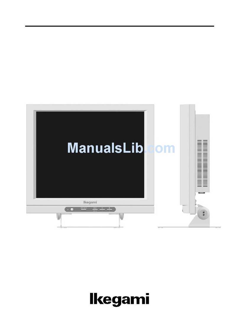
  9. Ikegami TM20-20RH User manual

Ikegami TM20-20RH User manual

MODEL
TM14-20RH/RP
TM20-20RH/RP
·TM20-30RH/RP
COLOR MONITOR
OPERATION MANUAL
ll<egarni
[;
r··
r
,·
l
[-
r·,
r :
[:
(!
_,
(
I__
[_._
.j
["''.
11 PRECAUTIONS, 1
In order to use this monitor safely, please read this entire m1rnunl and pay particular attention to the following
items.
1. Do not use any power supply other than the
regulation AC power.
2. Do not subject the monitor to strong impact.
Not only can this lead to breakdown, but it is
dangerous because of the possibility of the CRT
imploding .
3. Avoid storing or using this monitor in any of
the following locations.
1) Locations hotter or colder than the regulation
temperature .
If you place the monitor too close to a heat
source or block off the ventilation hole in the
cabinet, the temperature inside the monitor "'ill
rise. Not only will this reduce the life span of
electrical parts, but it can also lead to
bre11kdowns.
1, WARRANTY , 1
If you can not get a. picture even after making the
chii!y adjn~tments and you think the monitor may be
broken, please contact your local Ikegami dealer or
Ikegami Tsushinki directly.
1, ACCESSORIES 11
Make sure that the following accessories have come
with the monitor.
1. Operati on manual
2. AC cable
3. Remote connector
2)Locations subject to rain, snow, or excess
humidity
Such locations can ca.use electrical leaks and
breakdowns .
3) Locations with strong magnetism
4. Avoid exposing the CRT to direct sunlight.
If the CRT is subject to direct sunlight for a
prolong('d period, the fluorescent screen within th~
CRT will deteriorate, so be careful if ·using this
monitor outdoors.
* These specifications and appearance are subject to improvement without prior noti ce.
-1 -
CONTENTS
1. OUTLINE ............... ..... ...... ...... ................. ,........ 3
2. FEATURES····· ...... ....... ................. ...................... 3
3. SPECIFICATIONS· ·········· ....... .................. ...... ... ... 4
3-1. General····· ···········..····························..······ 4
3-2. Input Signal········ ········ ··················· ...... ....... 4
3-3. Rating ·..··········· ·... ····· ··..··········..····..····· ···· 5
3-4. Brightness and Contrast ··········.... ···········..··· 5
3-5. Output ····..··..... ·····..········.... ········..····....···· 6
3-6, Luminance Signal and Video Signal Systems ... 5
3-7. Chrominance Signal System..... ... ....... ........ .... 6
3-8. Deflection and Sync Systems ··········· ·..····..···· 6-
3-9. Functions· ··· ..······ ..···· ··· ·..·..··· ····· ·..··..········· 7
3-10. Memory .... .... ............... ........................... · 7
3-11. External View
TM14-20RH/RP ···...·············..··..·· K3-950009-3
TM20-20/30RH/RP ....... .......... .... K3-950008-4
4. INSTALLATION ...................................... .... ...... 10
4-1. Connection with External Equipment ···..···..·· 10
4-2. Parallel Remote Connector
Connection Procedure ·····
..... ···..····... ······..··· 10
5. DAILY ADJUSTMENT ·..·..·..·.....·...... ...... ·..··..···· 12
5-1. Power·· ..····· .... ·..··..··· ..···· ..···· ···· ..·..·········· 12
(1) Power ON .... ···· ........................ ········ .. 12
(2) AC Input Supply Voltage and Fuse ...... 12
5-2. Front Left Operating Section ····.... ·
..······ ··.. 13
(1) Degaussing ·..·..·····.... ·....·..·..···..··..···..·· 13
(2) Warning LED ............. .... ................... 13
(3) Remote Sensor ······............ ..... ..... ... .... · 13
5-3. Names and Functions of the Control Section 14
(1) Names and Functions of the Front
Panel Operation Section ···..···..········..· 14
(2) Names and Functions of the Pull-out
Pa.nel Control Section ................ ........ 19
5-4. Adjustment Procedure· ··... ,.... ......... ........ ..... 25
(1) White Balance Adjustment .................. 25
(2) Color Balance Adjustment ··
..··..... ·..···· 25
{3) Focus Adjustment ..·····..··... ·..·..····.... ·· 26
(4) ROTATION Adjustment ... ........ .......... 26
{5) Brightness Adjustment ..·······....··········· 26
(6) Contrast Adjustment ····...···.... ··..·....···· 27
(7) H.CENT and V.CENT Adjustment .... .. 27
(8) H.PHASE Adjustment ..···..······· ····..···· 27
5-5. Memory Storage and Change .............. ....... 28
(1) Changing PRESET Data .... .... ... ..... ... ,. 28
(2) Changing FILE PRESET Data ..···..... ·· 29
5-6. Menu Operation ..····......... ····· ········..·..····.. 31
(1) SAFE TITLE ............. ........ ....... ..... ... 34
(2) SPLIT ··················..········..·····...···.... ··: 35
(3) USER DISPLAY ·····..····... ···..··..·········· 38
(4) SYSTEM ................ ........................ .. 39
(5) INPUT ·········· ·
..·..···..··..··..····..·..····· ·· 42
(6) MODE ....... .................... .............. ....... 43
(7) STATUS········ ............... ...... ....... ...... ... 45
(8) LOCK ............................. ............. ...... 46
5-7. Messages Displayed on the Screen ··.... :........ 47
6. SUMMARY OF OPTIONS ·............. ........... ....... · 49
6-1. Digital Kits ········· ··.......................... :......· 50
6-2. Various Decoder Boards..... ............. ............ 50
6-3. Faroudja Comb Decoder Board(only NTSC) ··· 50
6-4. Special Function Module (SF301) ............ ... 51
6-5. Auto Set Up Probe (ASP-15) ..... ·····.... ······· 51
6-6. Infrared Remote Control (RCT-20) ··· ····....... . 51
6-7. Dual Component Module (DC3op .... ..... ...... 52
6-8. Rack Mount Adaptor ·..·······..····...····.... ··..·· 52
6-9. Terminate Plug (TP301) ................. ......... . 52
6-10. Service Manual ..... ........ .... ........... ......... .. 52
7. REMOVAL OF COVER ··..·····..·······..····..·..·..······· 55
7-1. How to Remove the Cover ·······..··.... ········· 55
(1) Removing the Top Cover ···..··········..···· 55
(2) Removing the Side Cover ·..··..······.....··· 55
(3) Removing the Rear Cover.... ... ........ ...... 56
7-2. Internal of the Monitor ........ .... ........ ··· ... ···· 56
(1) TM14-20RH/RP ...... ...... .... ..... ............ 56
(2) TM20-20RH/RP, TM20-3 0RH/RP ... ..... . 57
- 2 -
n
Li
u
.
'
·"
0
G
.
'
n
Li
['.
'
.}
E
l
'
~'
C
'
...}
0
.
;J
0
'
.
D
'
'
E
.,
".
'
.
C
l·.''j
'
i.
.;,:,
{·:
~
[-:,
.i
J
....._,
[·._.·.·.
.-<i
[·
r..
I
l '
[··
r..
I
[,
[
r
I.;
r··
t .
[.
l_·
L.
1. OUTLINE
This series color monitors have the input systems suited to
the diversified system needs. In addition to 3 video input
systems, au RGB input system or a YPoPn input system is
provided as a stand ard equipmen t. A Dl, D2 or D3 input
syste m (2 serial inpu t systems and 1 parallel input
system) or a Y/ C inpu t system can be provided as
an optiona l equipment, RGB and YPnPn can be
corresponded to various standard s and you can adjust the
chroma level by front pane l. When the optional decoder
board (P AL or SECAM) is inserted into the SLOT section
in add ition to NTSC decoder board, this monitor can be
made automatic ally to operate with 2 format signals. Thus
this product is the maste r monitor for the professional
with the various functions, fine performa nce and stability
which is corresponded to various broadcasting system and
used for the final check of th e video signal.
2. FEATURES
(1) High-performanceinline GunCRT
This monitor uses an iuline gun dot mask high-deta il
CRT. The dot mask pitch is a fine 0.31 mm for the
TM14-20RH / RP , 0.43 mm for th e TM20-20RH/ RP,
and 0.28 mm for the TM20-30RH/ RP.
Since the CRT for the 20 series (the same CRT as f9r
the 15 and 19 series) coats bismuth oxide (BiO) on
the shadow mask and th e 30 series uses inver material
for the shadow mask mat erial, th e doming (beam
displacement due to thermal deformation of th e
shadow mask) when the brilliance is raised is greatly
reduced.
(2) DigitalControl
Control is completely digitized with an 8-bit MPU
and 10-bit D/ A converter . Therefore, various status
displays are possible and aut o setup 'can be carried
out by j ust adding the probe. Since control uses
rotary encoders, you can adjust with the same feeling
as with the analog contr ollers you have used up till
now.
(3) Auto Setup Function
The optional ASP-15 auto setup probe can be used to
automat ically adjust the factory setting color
tem perature . Also, if you hav e the probe memorize
the operator's unique color temper ature, then you can
automati cally set any number of monitors (15 series,
18 series, 20 series, 30 series) to that color
temperat ure.
(4) 4 ColorTemperaturescan he StoredInto Memory
This monitor can store three color temperatures in
addition to the factory setting. This means you can
quickly and easily select the whit e balance sett ing
best for th e state of the input image and the usage
objective .
(5) RemoteControlFunction
In addition to the standard parallel remote connector,
there are also an opt ional infrared wireless remote
controller(RCT-2 0) and an optiona l *serial control
box that can use a loop through connection with a
BNC cable.
Any single one of these remote contro llers can control
up to 99 monitors.
* ..· mad e-to-order
(6) BeamFeedbackSystem(BFS)
The beam feedback system, which detec ts the CRT
cathode current, provides images with stab le white
balanc e for a long time.
(7) Built-inCCDCombFilter(only NTSC )
The CCD lH-delay line greatl y improves the cross
luminance and the cross color. Also, the optional
Faroudja comb decoder provi des an image with no
cross luminance in the section with no vertical
relationship.
(8) SufficientInputSystems
Th ere are four inpu t system s, thr ee composite video
input and one RGB or Y/ PB/Pn (Y/ B-Y/R -Y) input.
(Th e lat ter can be switched between RGB and Y/
Pa/Pa with the pull-out panel ~peration section.)
Optio ns are 8/ 10-bit digital (Dl , D2, D3) input and
Y/ C input. In addition , th e DC301 dual component
board can be used for 2-chann el component input .
(9) Built-inGenerators
Five different types of test signals (cross hatch, flat
field, window, chara cter, and step wave with pluge
signal) and you can switch the output format between
525 (60 Hz)and 625 (50 Hz) with simple menu
operations. Safe title signals (80%, 85%, 90%, 95%,
100%, 80+90+100 %, 5-partition cross hatch, and 10-
partition cross hat ch) are built in as sta ndard features .
(10) VideoBoardModularization
Th e video syste m boards are plug-in type. To make
repairs and checks easier, the video, def(lection), and
power boards can be removed with the monitor itself
still in its rack.
-3 -
(11) Component Input that Meets Various Standards
In order to meet such standards as M Il, Beta, N-10,
and SMPTE, R-Y and B-Y levels relative to the Y
level can be adjusted freely with the CHROMA
manual contr ol on the front pan el and by just
setting the standard to use with the pull-out panel,
you can automatically switch the chroma preset level.
The chroma level can also be adjusted freely for RGB
signals.
(12) Handles All Three Formats: NTSC/PAL/SECAM
In addition to the standard decoder board, a variety
of option decoder boards can be mounted in slots to
automatically monitor composite signals in all three
formats , NTSC/PAL/SECAM on a single monitor.
Also, since the deflection system is adjusted to be able
to handle 525 (60 Hz) and 625 (50 Hz) formats with
the standard configuratio n, if the signals are analog
component signals (RGB, Y/ Pn/Pn) or digital
component signals (Dl ), you can monitor signals in
almost any format without a decoder board .
(13) Digital Input
Digital input can be corresponded to parallel and
serial inputs for Dl, D2 or D3. The circuit treats by
10 bit. You can switch to 8 bit or 10 bit by front
panel operation . Because of using the filter built-in
x/S IN x correction based on the 601 of the CCIR
recommendations in post filter, the faithful converting
digital int o analog is possible.
(14) V/VS (0%/7 .5% set up) Function
The V/VS function is the function to switch ·the
clamp level (black level) of the monitor in
conformity to the set up level (0% or 7.5%) of input
signal. Because the V/VS setting can be set with
each channel by menu operation, if the set up level of
selected signal is changed, keeping the black level
fixed is possible .
3. SPECIFICATIONS
3-1. General
(1) Power: Single-phase 50/ 60 Hz AC
100 V - 120 V/200 V -240 V ± 10%
Approx. 160 W
(Automatic switching between 100
VAC and 200 VAC)
(2) Ambient Temp erature :
O'C- 40'C
(3) Humidity : 90% or above
(however, no condensatio n allowed)
(4) Dimensions and weight:
TM14-20RH/RP : 450 (W) x 265 (H) x 515 (D)
approx. 26 kg
TM20-20/30RH/RP: 450 (W) x 399 (H) x 515 (D)
approx. 38 kg
(5) Standard accessories:
Power cable, Remote connector,
Operations manua l (One each)
(6) Demodulation:
(7) Operation : R-Y/B-Y System .
Continuous
(8) X-ray Emission: 0.1 mR/H or less (At all locations
50 mm from the outside of the
monitor)
3-2. Inputsignal
(1) Composite video signal:
BNC 3 systems (loop through)
(2) RGB or Y
/Pn/Prt signal : *1
ENC 1 system (loop through) *2
(3) Digital signal (option) : *3
Dl (digital components)
D2, D3 (digita l composite)
Parallel input :
Serial input :
Serial output :
D-SUB 25-pin 1 system
(single end)
BNC 2 systems(single end)
ENC 1 system
(monitor output) *4
*1 For details on RGB/Y /Po/Pn switching, see 5-6.(5).
*2 When the optional dual component board is used, 2
input s can be used. However, in this case, loop
through connection is not possible.
*3 Dl, D2, and D3 can be switched between 8 bits and
10 bits for usage . Use switching between parallel
input and serial input. For details on how to switch,
see 5-6.(5).
*4 The digital signals (parall el or serial) selected on the
monitor are output serially.
-4-
]
,·1.•
.!
,_..]
"
~_.··.·i
' .
...
,·..·
' )
,:I
. ]
J
]
···i
:..
J
Cl
LJ
[·.·.·
·_:,
r:
i":
i
f'
['.··
1.
('
l..
\..
[.
!··
[ .
1·1
I .
3-3. Rating
(1) Input levels
· Composite input
VS : 1.0 Vp-p positive polarity
V: 0.7 Vp-p positive polarity (Japan, Europe)
V: 0.714 Vp-p positive polarity (U.S.A.)
· Sync input
4 V - 6 V p-p negative polarity
· RGB input
VS : 1.0 Vp-p positiv e polarity
V: 0.7 Vp-p positive polarity
· YPoPn input
When R, G, and B all have sync
signals, when only the G signal has a
sync signal, or when neither R, G, nor
B has a sync signal
The standard input is Beta or M Il {SMPTE, NlO)
Beta <525/60 Hz>
Y signal White: 714 mVp-p
Setup: 53.6 mVp-p
Sync : 286 mVp-p
Pn, PR signals: 700 mVp-p
(100/ 7.5/75/7 .5 COLOR BAR)
<625/50 Hz>
Y signal White: 700 mVp-p
Setup : 0 mVp-p
Sync: 300 mVp-p
Po, Pn signals: 700 mVp-p
(100/ 0/75/0 COLOR BAR)
M Il (SMPTE, NlO)
Y signal White: 700 mVp-p
Setup: 0 mVp-p
Sync: 300 mVp-p
Pn, Pn signals : 525 mVp-p
(100/ 0/ 75/0 COLOR BAR)
The monitor can be set from the front panel for
signals other tha n standa rd.
· Y/C input
Y signal : 1.0 Vp-p (VS)
C signal: 0.286 Vp-p (burst level)
· Digital input
ECL 10 K (8-bit or 10-bit)
(2)Input Impedance
Composite input, sync input, RGB input, YPnPa
input
Y/C input
High-impedance bridge connection or
75!"1terminator
(75!2 terminator plug is optional )
High-impedance bridge connection or
75!"1terminator (switched)
Digital serial input 75il terminator only
Digital parallel input 110.I?terminator only
(3)Return Loss 46dB or high (10MHz)
3-4. Brightness and Contrast
(l) CRT: In-line electron gun dot shadow mask
(2)Horizontal Resolution:
Dot trio pitch
TM20-30RH/RP : 0.28mm
TM20-20RH/RP : 0.43mm
TM14-20RH/RP : 0.31mm
When screen center is 35 Ft-L
TM20-30RH/RP : 900 lines or greater.
TM20-20RH/ RP : 700 lines or greater .
TM14-20RH/RP : 700 lines or greater.
(3)Preset Contrast :
Factory setting is 35Ft-L
(100% window signal input)
(4)Maximum Brightness:
TM20-30RH/RP : 50 Ft-L, or greater
TM20-20RH/RP : 50 Ft-L, or greater
TM14-20RH/RP : 70 Ft-L, or greater
(At 100% window signal input,
BRIGHTNESS PRESET,CONTRAST
MAX.)
3-5. Decoder Out (Option)
y: 0.7Vp-p
Pn, Pn: 0.525Vp-p
(100/ 0/75/0 COLOR BAR)
This applies at the time of signal input
for composite video, composite digital,
and analog componE·nts (for RGB and
YPnPn).
High-impedanc e output.
3-6. Luminance Signal and Video Signal Systems
(1) Frequency characteristic
60 to 10 MHz +1, - 3 dB RGB input (NTSC)
50 to 10 MHz +1, -3 dB RGB input (PAL)
(2) Luminance Signal System
a)Fr equency respon ce:
±ldB at 50 to 7MHz (Notch OFF)
- 30dB at 3.58MHz (Notch ON)
b) 2T pulse and 2T Bar T pulse (KPn):
± 1% (Notch OFF)
± 2% (Notch ON)
c)Short-time Distortion (Ksn):
± 1% (Notch OFF)
± 2% (Notch ON)
d)Sag: · ± 1%
e)Linearity (DG):
Below 2%
- 5 -
f)Black Level Stability :
1% or less for APL variation of 10% -
90%
g)Color Temperature Stability :
Below 1% after 500 hours of.operation
at l0"C - 40'C
h)Aperture Correction :
(3)Noise:
Sync noise:
Hum noise:
Random noise :
With subcarrier trap on, 2T pulse
overshoot is symmetrical.
Above -4 6dB
Above -55dB
Above -55dB
3-7. Chrominance Signal System
(!)Frequency responce:
At chroma signal test pin
NTSC: 3.58MHz ± 1MHz + 1, -3dB
PAL : 4.43MHz ± 1MHz + 1, -3dB
(2)Demodulation -axis phase difference :
go• ± 1·
(3)Subcarrier frequency syncronizing range:
Lock in range NTSC : 3.579545 MHz±200 Hz
PAL : 4.43361875MHz±300Hz
(4)Phase Difference (only NTSC):
Below 2°
(Burst frequency ± l0Hz, Burst level
+6dB, -1 2dB, Change in atmospheric
temperature l0 "C, Where positions of
the H-SYNC signal and the burst
signal change within FCC standards)
(5)Delay compensation :
Delay time compensation error from
luminance and Pn,Pu channel is less
than 0.02µSEC.
{6)Color killer operating point:
Automatically operat ed when the burst
level is 5 ± 1 IRE.
(7)Adjusters : Chroma level Above ±6dB
Chroma phase ± 15°
3-8. Deflection and Sync Systems
(1) Picture size: a)NORMALSCAN(4:3)
1% over-scan of effective CRT screen
b)UNDERSCAN(4:3)
Approx. - 7.5%of effectiveCRT screen
c)UNDERSCAN(16:9)
Widthis the sameas UNDERSCAN
(4:3)
and the aspect ratiois 16:9.
(2)Stability of Raster Size
When CONTRAST and BRIGHTNES S
are preset, when the APL changes
within 0o/'o-100%,there is a variation of
1% or less.
(3)Deflection distortion
a) Deflection of axis
Below 0.5%of the height ofthescreen
b) Overall screen distortion
B~low 0.5% of the height of the screen
{4)AFC time constant
NORMAL : 2mSec.
FAST : 0.5mSec.
SLOW : 7mSec.
{S)Syncstability: Operation will be stable when the
input signal falls within the following
parameters :
Internal sync :
Variation of ± 6dB in rated video
input level values
External sync :
{6)High voltage:
Negative voltage applied to external
sync input terminal
0.3 to 8Vp-p
a)Output volt age
TM20-30RH/RP : 25kV
TM20-20RH /RP : 25kV
TM14-20RH/RP : 25kV
b)Voltage fluctuat ions:
Within ± 1% for beam current of
between Oto 450µA with 150 µA as
a reference
(7) Convergence :
20 SERlES
· Cente r : 0.2 mm
· Withi n 80% circle of screen height
: 0.3mm
· Other than above
: below 0.5 mm
30 SERIES
·Ce nter: 0.15 mm
· Within 80%circle of screen height
: 0.3mm
· Oth er than above
: below 0.45 mm
-6 -
]
l
l
...1
..
,-]
,·
...J
]
J
J
.
,·:l
:.··.·
L.:.:
r·
!
I
I
\·
[.·:
'
[.·'
!
1·
I
l_
l·.
,
.:..
l
1·.
L
!
·:.
. '
!
• ,i
_;_,
3-9. Functions
(1) Faroudja comb decoder (option)
(2) Safe title generator
(80%, 85%, 90%, 95%, 100%, 80+90+100%,
5-partition cross hatch , or IO-partition cross
hatch is selected and displayed)
(3) Auto setup probe (option)
(4) Infrared remote control (option)
(5) Remote control throug h serial interface (option)
(6) Built-in test signals
a) Cross hatch
b) Flat field
c) Window
d) Characters
e) Step wave with pluge signal
(7) Video A/B split (variable)
(8) Color/mo no split (variable)
(9) Beam feedback system
(10) Menu assist
a) Safe title
b) Split
Safe title color and screen display
position settings
A/B split and color/mono split screen
partition position setting
c) User display
User display color and character
setting
d) System
e) Input
Built-in board verification
Scanning format setting
Test pattern output setting
Delay bright setting
Input signal setting
f) Digital/ Analog
Data selecting in the serial remote
g) H phase
H phase memory setting
h) Level display
Preset level screen display setting
i) Delay
Delay mode setting
j) Screen
Screen mode setting
k) User display
User display output sett ing
1) Backcolor
Menu screen background color setting
m) Status
n)J;,ock
Control level display
Contra.st, brightness , chroma , hue, R/
G/B background, G/B gain, rotation,
aperture level, fine focus, height, width,
H centering, V centering, H phase
Software lock selection
3-10. Memory
(1) Memory type
ROM ; 32 K byte programmable ROM
RAM ; 8 K byte static RAM
(2) Battery backup
- 7 -
Memory retention period ; above 10 years
Battery ; Lithiu m battery(BR2330-1 HF)
3-11. ExternalView
j
I
., I
'
I
'
I
'
I
'
nn rh
I I I i I''
: I : : 1!1i
I I ·1
1 I I ii
i I I i UJ
1........£.....J
® I
w t:J w w '
r...1
II
I I
I!
• I
t.....J
@
V
r""i
i I
I :
I I
I :
I i
! i
I i
1.-..J
11111111111111
I
3---
I
'
'
- _ __ _J___ __
I
*
I -
'
I
'
I
D o!..o.o
I
i
8---
1 n Et
®1-1-- -
190 ._
i •
s---
C>
""
~
...
•• -+ --
e ..
@B
tL
'"
.....
""
....
-- -
---- - -- -- -- -- --
0000
00EH!>
.. 000 @
00El -~
-8 -
..
..
e tJ
TM14-20RH/RP
COLOR MONITOR
EXTERNAL VIEW
Kl-950009-3
~J
;J
·1
·_J
j
: -l
:,__:J
j
j
h)
u
[:.
L--,
f:-:
I:..
i . D
I
I
L.
I
l
I
'
I
'
I
'
I
'
I
rn
I I£
i i
I 1· l
: i
IiI
i.-r
rl r-1
I : i
I i I i
I i= i I
I i Ii:!
i i
I._ I r !
................,
@
..
...
.,,
.,,
n6 6£
D
·n
I i
: :
i i
: i
kaJ
@
-9-
0000
8000
•
TM20-20RH/RP
TM20-30RH/RP
COLOR MONITOR
EXTERNAL VIEW
Kl-950008-4
4. INSTALLATION
4-1. Connectionwith ExternalEquipment
· Input RGB or YPBPRsignals here. Refer to
Section· 5-6.(5) for details on switching
between RGB and YPnPit.
· When not looping through, conllect the
optional terminator plug.
· With the optional Dual Component board
(DC 301), two inputs (single end) can be
used.
AUX
INPUT
e~e
0G/Y
0~0
REMOTE
· Plug in the remote connector
· See 4-2 for the pin connections.
4-2. ParallelRemote ConnectorConnection Procedure
(Notes)
· Input composite video signals here.
· When not looping through , connect the
optional terminator plug.
· When using the optional _Y/C input, CH C
can not be monitored. Refer to Section 5-6.(5)
for details on switching between Y/C and CH
C.
VIDEO
INPUT
0~0
0~0
0 ~
0~
· Input the video input and AUX input
external sync signals here.
· When not looping through, connect the
optional terminator plug.
From the program version2.1 (displayedon the upper right of the MENU1 screen), PARALLEL/REMOTEfunctionsare
changed asfollows:
(1)Functionalchanges
Pin No.5: SYNCINT (GND)
/EXT~ DIGITALON (GND)/OFF
PinNo.8:
V(GND)/VS
~
16:9 (GND)I4 :3
(2)Whileinthe oldversion,frontpanelswitchesrelated to those on the remoteside are disabledwhen thelREMOTElswitch
is ON,fromversion2.1,the frontpanelswitches are operablewhen those on the remote side are in opening condition.
(3)SYNCINT/EXTandV/VSare automaticallyswitched to their preset statuswheninputchannels are switched.
- 10 -
,-_··--1
..
,-)
J
J
J
J
J
[.
I·
[
I
!
!, ..
t·.
l..
[_
[..
I ;
t..
· To enable remote operation through the parallel remote connector, use the IREMOTEI switch on the pull-out
panel to select parallel mode and switch On. See 5-3.(2).
Fromthe programversion2.1(displayed onthe upperright ofthe MENU1screen), the ON/OFFcontrolofTALLYand 4:3/
16:9can be doneirrespectiveofthe!REMOTElswitchoperation.
· Connect the accessory remote connector according to the figure below.
ON AIR TALLY
ON AIR TALLY 2 --~'~Si
..2
CH AUX select 3
CH e select 4 ..2
CH I
CH DIGITAL select 5 ..2
OlCllTAL
COLOR/MONO ,elect 6 COLOA
MOHO
GROUND 7
4 :3/16 :9 select 8 *3 4 :3
CH C select 9 •2 l6 :
~
CH C
100
Fig. 4-1. Remote Connector Connection Procedure
*'
*l Tally control can be implemented externally or from
within. the power supp ly. When implementing
from within the power supply, short Pins 2 and 7
to each other. When implementing externally,
supp ly 12 VDC or 24 VDC between Pins 1 and
2. (The polarity does not matter.)
*2 The switchingofinputsignalscanbedone smoothlyusinginterlockswitches,as illustratedbelow.
(1)SwitchingofAB C,AUX (2)SwitchingofDIGITALA/Binadditionto (1)
Connector Q'°(o ! A ON
! BON
! CON
! AUXON
Connector ofo
(4)--t----o'fc· I
{Ql---t---- -<J).,.
! AON
! BON
! CON
i VIDEO ON
i AUX ON
! DIGITAL ON
*3 Theremote switchingof4:3/16:9canbe done regardless ofthe ON/0 FF statusofthe!REMOTE!switch.
WhenthelREMOTElswitchisON,theSCANswitchonthe frontpanelisnotoperable unlessthe switchis open(4:3position)
on the remote side,while,when thelREMOTE!switchis OFF,the[s"CANlswitchon the front panelis operableeven if the
switchisset to 16:9onthe remote side.
~ TALLVUW
<TM14-20RH/RP>
00= Cl ~~'OOOQl--
u u
<TM20.20/lORH/RP>
Fig. 4-2. Position of TALLY LED
- 11 -
I~
•...
•·0
•·0
• ·O
1,0
5. DAILY ADJUSTMENT
Under normal usage conditions, the prescribed performance can be obtained by just operating the adjusters below.
The switch LEDs in the explanation below express the following meanings :
~
... LED Off I~I·..LED blinking 0 ··· LEDOn
5-1. Power
POWERIN
[J
AC1 00V -A C120 V
AC200V-A C2'0 V
FUSE 4A
@ (i)FUSE
MAIN
0 POWER
I
I I --~---®MAIN POWERSWITCH
Fig. 5-1 Rear Panel
(l)Power ON {2)AC InputSupplyVoltage and Fuse
After switching "ON" the !.MAIN POWER] switch
indicated by ® on Figure 5-1, if you switch "ON" the
IPOWERiswitch on the front left panel, the POWER
LED lights up and the system comes on. (The system
is shipped from the factory with this switch "ON".)
When you switch the power off, it is normal to just
switch "OFF" the front panel !POWER!switch. There
is no need to switch "OFF" thelMATNPOWERjswitch.
- 12 -
Since the AC input voltage is switched automatically,
there is no need to change any switches when changes
lx>tween 100-120 VAC and 200-240 VAC.
& CAUTION
• Ifthefuse is burntout, checkthe circuittroublebeforechanging
the fuse.
• Tum the powerOFFbeforechangingbecauseanelectricshock
or troublemaybe caused.
• Besureto useafuse ofthe specifiedtypeand capacity.
]
:J
··.J.·
.·
:..J
:..!
.
J
.
,·J··
..
U
....
.
.
re
I
I
\
I
[.'
t
r
I
i.
(
1·.
I ,
L_
I.
t~.
5-2. Front Left Operating Section
<TM1 4-20RH/RP>
(l)REMOTE SENSOR
NO BURSTLED
@()VERLOADLED
@DEGAUSSswitch
@POWERLED
@POWERswitch
<TM20-20 /3 0RH/RP> @POWERLED
@OVERLOADLED
(DREMOTESENSOR
@NO BURSTLED
@DEGAUSSswitch
@POWERswitch
Fig. 5-2 Front Left Panel
(l)Degaussing
When the power is switched "ON" and this monitor
·starts up, the charged shadow mask is automatically
degaussed. You can also degauss at any time by
pressing the !DEGAUSS! switch indicated by © in
Figure 5-2. Pressing the !DEGAUSS!switch over and
over 11g11incontinuously lrns no effect, so after pressing
the switch, wait two or three minutes, then press
again.
(2)WarningLED
The WARNING LEDs ® and @ in Figure 5-2
indicate the following warning s.
® OVER LOAD LED
This LED lights · up when the ABL circuit
operates (when the brilliance rises too high) .
&CAUTION
Ifyou usethis monitorwiththe OVERLOADLEDlit upcontinu-
ously,theCRTwill deteriorate,so lowerthe brilliance.
® NO DURST LED
This LED lights up when there is no burst for the
signal for the selected channel (black and white
signal) or when the color killer circuit operates
{when the CONTRAST or CHROMA is fully off).
(3)RemoteSensor
The section indicated by CDin Figure 5-2 is the
photoreceiver section for the RCT-20 optional infra.red
remote control.
- 13 -
5-3. Names and Functions of the Control Section
Under normal usage conditions, the designated performance can be obtained by just operating the·adjusters below:
(1) Namesand Functionsof the FrontPanelOperationSection
141+--ll--- - - - - -- @HUE Manual Control
@DIGITAL Switch
@AUX Switch
Fig. 5-3-1. TM14-20RH/ RP Front Panel
@MO NO{SPLIT) Switch
(7)APT Switch
@ DELAYSwitch
@SCAN Switch
@!SAFE TITLE Switch
@s- PAL Switch
@)FILE LED
@COMB Switch @)BRIGHT Manual Control
@TEST Switch @)CHROMA Manual Control
@SYNC EXT Switch @HUE Manual Control
(!)INPUT SELECT Switch @SCRE ENS Switch
Fig. 5-3-2. TM20-20 / 30RH/RP Front Panel
- 14 -
-~./1
.·.
·.·1.
. ·1
-.~··1
..
'.·:.-]
..
:·1
'J
....·.1
"
':l
J
··i
,. ,
,·
;:.:)
LJ
r-·
f·-
t ·
,·
I
l
[·
i
r
\.
f
\_
[_
\._
1--
[_
l:
(D !INPUT SELECT! Switch
Use the [A] and [!J switches to switch the input
signal as indica ted below.
Since the input channels (composite signal input CH
A, B, C and A/B,and AUX signal input CH A and
B) operate auto matically linked to the !SYNC EXT!
switch, th ere is no need to operate the !SYNC EXT !
switch every time you switch the channel.
(a) When composite video signals are selected
[ CH A .--.. CH B _. CH C (Y/C) +--+ CH A/ B =1
· When CH C (Y/ C) is selected, to select the optional
Y/ C input (special function modul e SF301), use
Menu Item 3 (See 5-6.(5)) toselect Y/C input.
· The CH A/ B split splits the screen into top and
bott om so you can monitor the CH A and CH B
composite signals simultaneou sly (CH A on top and
CH B on bottom). You can easily adjust the color,
adjust the white balanc e, and check the video phase
for two cameras and two types of video signals. You
can change the screen split position and which sync
signal to use with ther method in 5-6.(2).
(b) When AUX signal selected ( IAUXIswitch is "ON")
· As a sta ndard, one input is equipped. Only CH A
can be selected.
· When opt ional dual component board (DC301) is
installed , switches as indicated below.
(c) When DIGITAL signal selected
~DIGITAL! switch is "ON")
· For CH A, the input (serial/para llel) which is set by
Menu in 5-6 is monitored and for CH B, the serial
input is monitored.
® !AUXISwitch
Wh en this switch is pressed, the LED lights and
signals input to the rear pan el AUX INPUT can be
monitore d. Wh en the switch is pressed a second time
the LED goes out and operation is changed to the
composite video chann el.
* Either the RGB signal or YPeP R signal can be input
through the AUX switch. Refer to Section 5-6.(5) for
details of. setting method .
Also, if the optional dual component board is installed,
dual system input is possible. In this case, it is
possible to switch between AUX A and AUX B using
the !INPUT SELECT !switch.
@ IDIGITALI Switch
When this switch is pressed the LED lights and
signals input through the optionally installed
DIGITAL input, can be monitored. Either DIGITAL
input Dl or D2(or D3) can be installed. When the
switch is pressed a second time, the LED goes out and
operation is switched over to the composite input
chann el.
* There are two types of DIGITAL input,· serial inpu t (2
systems), serial output (1 system: Monitor out) and
parallel input (1 system). With serial input it is
possible to switch between DIGITAL A and DIGITAL
B using the !INPUT SELECT! switch.
DIGIT AL A par allel A input
serial A input
Selected by MENU operation.
DIGITAL B serial B input
@ !SYNC EXTI Switch
· When using an external sync signal, set this switch
to "ON". The state of this switch is store d into the
memories of the input channels. When you set this
switch once, it is switched_over automat ically. For
example, it is set to "ON" at CH A and CH C and
to "OFF " at CH B. When you switch the channel to
CH A, B, and C in order with the !INPUT SELECT !
switch, the !SYNC EXTI switch is switched to "ON",
"OFF ", and "ON" in order.
Note) When the DIGITAL input is selected, you can
not operate this switch.
- 15 -
® ITESTjSwitch
Five types of test signals are built in as standard :
cross hatch, window, full white, character, and step
wave with pluge (for 525 line mode, two setup levels,
0% and 7.5%). In addition, you can switch the
output between 525 lines{60 Hz) and 625 lines(50
Hz). (See 5-6.(4).)
Also, V/VS of test signals are forced to set as
follows. For details of the V/VS setting, see 5-6.(4).
•
~
D
<Cross hatch>
Used for adjusting the linearity,
convergence, etc.
525 mode: VS
625 mode: V
<100% window>
Used for adjusting the white
balance, brilliance, etc.
525 mode: VS
625 mode: V
<50% flat field>
Used fo~ adjusting the purity,
rotation, etc. (See 5-4.(4).)
525 mode: VS
625 mode : V
<Characters>
Used for adjusting the focus etc.
(See 5-4.(3).)
525 mode: VS
625 mode: V
unit( %)
Used for adjusting the white balance (5-4.(1)), brightness
(5-4.(5)), etc. When the input signal is setup level 0%,
this signal is used for various adjustments.
<Step wave with pluge>
(setup 7.5%) :VS
525 line mode only
&r.1it(%)
When the input signal is setup level 7.5%, this signal
is used for various adjustments.
® IMONOj(SPLIT•Switch
Pressing this switch lights up the LED and makes
the picture black and white.
Pressing this switch and holding it for 2-3 seconds
makes the LED blink and prtitions the screen upper
and lower, with the same picture on upper in color
and on lower in black and white. The screen split
position can be adjusted with the method given in 5-6.
(2).
© IAPTISwitch
Pressing this switch lights up the LED and_applies the
aperture .
® IDELAY!Switch
When this switch is pressed, the delay state is changed
.with the mode set as in the figure below. For details
on the setting method , see 5-6.(6).
"NORM"
O[JH.DELAY
B VDELAY
EE3H&V.DELAY
[J NO~L
@ jSCANjSwitch
"H&V"
DIE]H&V
~ -DELAY
l
DNORMAL
4:3 (UNDER)scan, 4:3 (NORMAL)scan and 16:9 scan can
be switchedwiththis switch.
- 16 -
·-1
"]
:·]
:]
,-]
::J
··1
:...
J
:_J
· _·]·_·.
r·.
r.,
I
l..
,··
I
'
i
l
t
I-
I
I
I•.. •
I
I
'
\..
r
l.
!.
[·
I .
\
@!SAFETITLE)Switch
When this switch is pressed, a frame from 80% to
100% in intervals of 5% can be outp ut and at the
same time three frames of 80%, 90%, and 100% can be
output on the screen. 5-partition cross hatch and 10-
partition cross hatch can also be output.
r --- ,
I +
I I 80% (SAFE TI TLE AREA)
L --- .J
~
r--- ,
+ I
' '
I I 85%
L --- _j
~
r "l
+ I
'
I I 90%(SAFE ACTION AREA)
L -- - _j
~
r --- "l
I + I
' '
I I 95%
L --- _j
r --- -,
I + I
. '
I I 100%
L --- _J
BO%
90%
fir-"'===' 100%
111
iii + 111 80%, 90%, 100%
~
===-=lli
~
100%
[fflf0-pa,Htion e=hatcl,
'(Jr 100%
E 10-p,u·Hfon =,hatch
· The 80% frame expresses the safe title area of the
SMPTE recommendat ions and the 90% frame displays
the safe action area.
· Since the 95% frame is the same size as for over scan,
you can set the over scan size if you adjust the screen
size so that the escutcheon frame and the 95% frame
match.
· The 100% frame can be used for H. phase adjustment .
For details on the adjustment method, see 5-4.(8).
You can also visually check the video blanking width
and check the input signal video phases.
· 5-partition cross hatch and 10-partition cross hatch
can be used to set the position of the camera location.
@!COMBlSwitch
For composite video input, when the NTSC decoder
board is selected(NTSC mode), pressing this switch
lights up the LED and uses a CCD comb filter circuit
for luminance signal and chroma signal separation.
When the LED is off, a trap circuit is used.
The CCD comb filter circuit eliminates the drop in
resolution when the color signals are reproduced.
When the optional Faroudja comb decoder board
(DE305) is used, this comb circuit is always used and
separatio n does not switch to the trap circuit .
@!S-PALISwitch
For composite video input , when the PAL-B decoder
boa.rd is selected(function does not work when the
PAL/SECAM decoder board or PAL-M decoder board
is selected), pressing this switch lights up the LED
and makes the demodulation simple PAL. When th e
LED is off, the demodulation is delay PAL.
IDe ia.;-P ALu~~
0
llid~lay 1in-;-b-u~i~p le PAL ·1
j does not use a. delay line. It simply converts the
. modulation output to light as is. In other words, it
Iuses the average effect of the human eye and
· alternates every other scanning line between + and
I-to eliminate the color phase error. . _ . _ . _ .
@!SCREENS!Switch
These switches switch the R/G/B screens on/off.
There are two modes for the!SCREENSlswitches . For
details on the setting method , see 5-6.(6). When all
the screens are "ON", the LEDs are all "OFF".
Caution
When the SCREENS LEDs blink, this warns that
the memory backup battery is runn ing low.
Replace it with a new 3V lithium battery. For
deta ils on how to do t his, refer to the service
manual.
- 17 -
@IHUEIManualControl
This is the manual control for the one-piece manual /
preset switch. Pressing it lights up the LED and
extends the knob. In this state, the hue can be
changed. For PAL-B format demodulation, when the
IS-PALI switch is not "ON", this function does not
work. (However, this is only for composite signals.)
Note: When a PAL/SECAM decoder or PAL-M
decoder board is selected, this funct ion does not
work.
®ICHROMAIManual Control
This is the manual contro l for.the one-piece manua l/
preset switch. Pressing it · lights up the LED and
extends the knob. In this state, the chroma can be
changed .
@j BRIGHTIManualControl
This is the manual control for the one-piece manua l/
preset switch. Pressing it lights up the LED and
extends the knob. In this state, the brightness can be
changed.
The brightness for the delay state is adjus ted with
Menu Item 2.4. (See 5-6.(4).)
®! CONTIManual Control
This is the manua l control for the one-piece manual/
preset switch. Pr essing it lights up the LED and
extend s the knob. In this state , the contrast can be
changed.
@)FILELED
This LED shows the state of the FILE switch
discussed in 5-3.(2).
- 18 -
]
.]
--1
..~)
:1
:::1
,, • .
:·1
. .
..:.
J
j
::J
.J
LJ

Other manuals for TM20-20RH

1

This manual suits for next models

5

Other Ikegami Monitor manuals

Ikegami PM-960 User manual

Ikegami

Ikegami PM-960 User manual

Ikegami LCM-191 User manual

Ikegami

Ikegami LCM-191 User manual

Ikegami HTM-1990R M User manual

Ikegami

Ikegami HTM-1990R M User manual

Ikegami HPM-9050 User manual

Ikegami

Ikegami HPM-9050 User manual

Ikegami HLM-4600W User manual

Ikegami

Ikegami HLM-4600W User manual

Ikegami HLM-1510V User manual

Ikegami

Ikegami HLM-1510V User manual

Ikegami HTM-1505R CS User manual

Ikegami

Ikegami HTM-1505R CS User manual

Ikegami HTM-1550R User manual

Ikegami

Ikegami HTM-1550R User manual

Ikegami TM14-17RZ User manual

Ikegami

Ikegami TM14-17RZ User manual

Ikegami MLM-1581CH User manual

Ikegami

Ikegami MLM-1581CH User manual

Ikegami PM-127 User manual

Ikegami

Ikegami PM-127 User manual

Ikegami PM-209 User manual

Ikegami

Ikegami PM-209 User manual

Ikegami PTM-4202 User manual

Ikegami

Ikegami PTM-4202 User manual

Ikegami HMM-1850 User manual

Ikegami

Ikegami HMM-1850 User manual

Ikegami LCM-971 User manual

Ikegami

Ikegami LCM-971 User manual

Ikegami HQLM-3120W User manual

Ikegami

Ikegami HQLM-3120W User manual

Ikegami HTM-1517R User manual

Ikegami

Ikegami HTM-1517R User manual

Ikegami LCM-205N User manual

Ikegami

Ikegami LCM-205N User manual

Ikegami HDK-727 Manual

Ikegami

Ikegami HDK-727 Manual

Ikegami PM-9050 User manual

Ikegami

Ikegami PM-9050 User manual

Ikegami VCM-14DQ User manual

Ikegami

Ikegami VCM-14DQ User manual

Ikegami MLW-2622C User manual

Ikegami

Ikegami MLW-2622C User manual

Ikegami CCTV COLOR MONITOR User manual

Ikegami

Ikegami CCTV COLOR MONITOR User manual

Ikegami MLW-1712C User manual

Ikegami

Ikegami MLW-1712C User manual

Popular Monitor manuals by other brands

ViewSonic VE510s-4 Service manual

ViewSonic

ViewSonic VE510s-4 Service manual

Toshiba 65H84 brochure

Toshiba

Toshiba 65H84 brochure

Iiyama Pro Lite PLH430 user manual

Iiyama

Iiyama Pro Lite PLH430 user manual

NEC MultiSync P702 Dimensional drawing

NEC

NEC MultiSync P702 Dimensional drawing

Eizo FLEXSCAN L365 - brochure

Eizo

Eizo FLEXSCAN L365 - brochure

Philips 220S W9FS /00 Service manual

Philips

Philips 220S W9FS /00 Service manual

Envision G2470 manual

Envision

Envision G2470 manual

Eneo VM-UHD32M Quick installation guide

Eneo

Eneo VM-UHD32M Quick installation guide

Acer 193199140210 user guide

Acer

Acer 193199140210 user guide

Asus VP247TA user guide

Asus

Asus VP247TA user guide

SWIT Electronics S-1073F user manual

SWIT Electronics

SWIT Electronics S-1073F user manual

Panasonic TH-42PH30U Specifications

Panasonic

Panasonic TH-42PH30U Specifications

Samsung DB40E Quick setup guide

Samsung

Samsung DB40E Quick setup guide

Philips 104S Technical specifications

Philips

Philips 104S Technical specifications

Summer IN VIEW 2.0 PLUS quick start guide

Summer

Summer IN VIEW 2.0 PLUS quick start guide

Prestigio P7240W user manual

Prestigio

Prestigio P7240W user manual

Vicon VM-6215LED user guide

Vicon

Vicon VM-6215LED user guide

Wortmann Terra 2456W PV user manual

Wortmann

Wortmann Terra 2456W PV user manual

manuals.online logo
manuals.online logoBrands
  • About & Mission
  • Contact us
  • Privacy Policy
  • Terms and Conditions

Copyright 2025 Manuals.Online. All Rights Reserved.