IKUSI TM60 User manual

TM60Pi (06/00)
IKUSI reserves the right to modify this information without prior notification.
USER'S MANUAL
TM60
CONSOLE TRANSMITTER

TM60Pi (06/00) PAG. i
I N D E X
Pg.
1.- DESCRIPTION........................................................................................................ 1
2.- SAFETY PRECAUTIONS........................................................................................ 2
2.1.- What you must do.......................................................................................... 2
2.2.- What you must not do.................................................................................... 2
3.- INSTALLATION....................................................................................................... 3
3.1.- CB60 Battery charger.................................................................................... 3
3.2.- Receiver ........................................................................................................ 4
3.3.- Starting up..................................................................................................... 7
3.4.- Spurious ........................................................................................................ 9
4.- USING THE SET..................................................................................................... 10
5.- MAINTENANCE ...................................................................................................... 11
5.1.- Guarantee...................................................................................................... 11
5.2.- Precautions.................................................................................................... 11
5.3.- Preventive maintenance ................................................................................ 12
5.4.- Identifying faults............................................................................................. 13
5.5.- Spare parts.................................................................................................... 14

TM60Pi (06/00) PAG. 1
1.- DESCRIPTION
The TM60/3, TM60/4, TM60/5, TM60/6, TM60/7, and TM60/8 console type transmitter radio
remote control systems, are designed for the remote control of hoists and cranes (overhead
cranes, tower cranes, hydraulic loader cranes, concrete pumps, driverless vehicles, etc) and
are particularly suitable for applications when the operator needs to be able to choose the
best location from which to carry out an operation.
The system consists of a transmitter for selecting commands and a receiver which is
connected to the electrical system of the machine to be operated. The system also comes
with a battery charger and two rechargeable batteries.
The main specifications are as follows:
The TM60
Frequency band 405 a 475 MHz
Response Time 100 ms
Temperature range -20º a +65ºC
The TM60/3, TM60/4, TM60/5, TM60/6, TM60/7, and TM60/8 transmitters
Transmission power 10 mW
Protection IP65
The R60/9, R60/18, R60/26 and R60/38 receivers
Power supply 48, 115, 230 Vac ± 10%, 50/60 Hz
Optional 12 or 24 Vdc
Consumption 30 to 40 W, depending on models
Relays 230 Vac/8 A
Protection IP55
The CB60 battery charger
Power supply 230 Vac ± 10%, 50 Hz;
optional 115 Vac, 60 Hz or 24 Vdc
The BT12 batteries
Voltage 7,2 V
Capacity 1200 mAh
Charging temperature 5º a 35ºC
Autonomy 8 to 12 h, depending on models

TM60Pi (06/00) PAG. 2
2.- SAFETY PRECAUTIONS
These instructions must be read carefully in order to install and use
the set properly and to keep it in perfect working condition and to
reduce the risks of misuse.
Do not use this set on machines for the lifting of persons or in
potentially explosive atmospheres.
Any use other than that specified in this manual is dangerous. The
following instructions must be strictly adhered to.
2.1.- What you must do:
!Strictly adhere to the instructions for installation contained in this manual.
!Make sure that the installation is carried out by professional and competent personnel.
!Ensure that all site and prevailing safety regulations are fully respected.
!Make sure that this manual is permanently available to the operator and maintenance
personnel.
!Keep the transmitter out of reach of unauthorised personnel.
!Remove the transmission key when the set is not in use.
!On starting each working day, check to make sure that the STOP button and other
safety measures are working.
!When in doubt, press the STOP button.
!Whenever several sets have been installed, make sure the transmitter you are going to
use is the right one. Identify the machine controlled on the label for this purpose on the
transmitter.
!Service the equipment periodically.
!When carrying out repairs, only use spare parts supplied by IKUSI dealers.
2.2.- What you must not do:
!Never make any changes to the set, which have not been studied and approved by the
manufacturer.
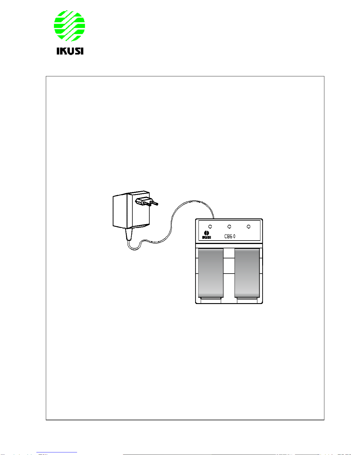
!Never power the equipment other than with the specified power supply.
!Never allow unqualified personnel to operate the equipment.
!After use, never leave the equipment ON. Always use the contact key or the STOP
button to avoid accidentally activating manoeuvres.
!Do not use the set when visibility is limited.
!Avoid knocking or dropping the set.
!Do not use the set if failure is detected.

TM60Pi (06/00) PAG. 3
3.- INSTALLATION
3.1 The CB60 battery charger
Connect the charger to the mains using the power source and cable supplied. On
installing the battery charger, bear in mind that the batteries must be charged at
temperatures over 5ºC and that the power supply must be left on all night. Also
remember that the charger must not be left in direct sunlight as the batteries will not
become fully charged at temperatures exceeding 35ºC.
Place the batteries in the charger. The LEDs should light up, indicating that recharging
is in process. Complete recharging takes 12 hours, but the batteries may remain in the
charger for an unlimited period of time.
The capacity of the batteries decreases with use. Their life span is estimated to be 500
recharging cycles, but this depends largely on the conditions of use, for which the
following is recommended:
!Do not recharge the battery until it is completely flat. The transmitter indicates
this.
!Always charge the batteries at temperatures between 5º and 35ºC.
!Avoid short-circuits between the battery contacts. Do not carry charged batteries
in tool-boxes or next to other metal objects (keys, coins, etc.)
!Always keep contacts clean.
!Never leave batteries in direct sunlight.

TM60Pi (06/00) PAG. 4
3.2.- Receiver
Make sure that the crane is stopped for the entire duration of the
assembly process, keep the work area free and wear protective
clothing.
Park the crane and position stop-ends, (if these are not available use
appropriate signs), at a suitable distance so that it is not hit by other
cranes on the same runway.
Check the power-supply voltage and turn off the mains switch.
Find a suitable location for the receiver, away from any intense radioelectric
disturbance source and install the receiver cabinet using 4 elastic absorbers.
The receiver antenna must be placed free of shielding by metal parts which could
obstruct reception of the signal. If this is not possible, please request an antenna with
cable extension.

TM60Pi (06/00) PAG. 5
There are three ways to connect the receiver box to the crane's electrical installations:
!Using multiwire cable.
!Using a multipin connector in the receiver box.
!Using a cable with a terminal multipin connector.

TM60Pi (06/00) PAG. 6
Connect the power supply and the receiver outputs on the corresponding relay board
plug-in terminals. Do this following the outputs diagram, which is supplied with the set.
This diagram indicates the connection between the transmitter commands and the
receiver outputs.
The KSTOP1 and KSTOP2 relays are in series and must be connected to the main
contactor coil circuit.
The K2/START is activated once the start-up command is held down.
The K1/SEC relay is a security relay which is activated when certain commands
predefined as “active” on configuration of the set, (i.e. commands which give rise to
manoeuvres), are activated.
Remember to connect the ground cable.
Only use fireproof cables for connections.
Select the appropriate voltage on the receiver, (230, 115 or 48 Vac).

TM60Pi (06/00) PAG. 7
3.3.- Starting-up
Proceed with caution; the equipment may not be connected correctly
which may lead to unforeseeable movements on starting-up.
Once the receiver has been connected, disconnect the power supply to the motors(for
example, by removing the fuses) and power on the receiver. The following receiver
LEDs should now light up.
POWER: indicates that the power supply is correct.
HARD: two LEDs on the relay board and on the logic board indicate the absence
of defects on the boards.
Next, place a charged battery in the transmitter and turn it ON. To do this, turn the
contact key, push and pull out the STOP button and press the start button. The green
LED should light up, indicating that the transmitter is transmitting.
1.- LED 4.- STOP button
2.- Start button 5.- Command elements
3.- Contact key 6.- Label for crane identification

TM60Pi (06/00) PAG. 8
On receiving a signal from the transmitter, the following LEDs will light up on the
receiver:
SIGNAL: this indicates that it is receiving an RF signal at the working frequency.
DATA: this means that the data format is correct.
ID: this means that the receiver has recognised the transmitter’s identification
code.
Now, the KSTOP 1 and KSTOP 2 relays will be activated. K2/START relay is activated
only meanwhile the start button is pushed.
Press on any of the transmitter’s manoeuvre buttons and its corresponding relay will be
activated and its LED will light up. In case of an active manoeuvre, the safety relay
K1/SEC will also activate.
Check to make sure all the other manoeuvres work in this way.
Turn off the transmitter using the STOP button, and make sure that on doing so the
relays are deactivated and the DATA, ID and SIGNAL LEDs go out.
Reconnect the power supply to the motors, move to the usual work position and check
to see if all the manoeuvres and the STOP buttons are functioning correctly.
Remember that the receiver has several voltage-powered circuits.
Even when the power has been cut off, there is still a risk of electrical
shocks.

TM60Pi (06/00) PAG. 9
3.4.- Spurious
The receiver is designed to become blocked if there is intense spurious disturbance
arising from galvanic, inductive, or capacitive coupling, thus preventing unwanted
manoeuvres.
As a precautionary measure, it is recommended that spurious-preventing devices
(diodes, capacitors, RC circuits) be fitted at the source of the disturbance. These devices
should be connected directly to the contactor coil terminals, electro-valves, etc. and can
be obtained from the usual contactor suppliers.
If the equipment is installed on a vehicle with a friction power supply where electric
arcs are produced as a result of defective contact, an RC circuit should be fitted
between each phase and earth.
Spurious-preventing devices should also be fitted when installing the set on a spark
combustion engine vehicle.

TM60Pi (06/00) PAG. 10
4.- USE
To ensure correct use of the equipment, follow the instructions below:
!Make sure the transmitter you are going to use is the right one, identifying the machine
on the identification label.
!Attach the belt to the transmitter unit. Its use is recommended to prevent the
equipment from falling.
!Introduce a charged battery, turn the contact key. This will activate the transmitter.
!To activate the system, you must first pull out the STOP button, the green LED should
then give a green pulse; then press the START button. If you find that the STOP
button has already been pulled out, it is necessary to push it in and then pull it out
again, as this sequence will allow the check in of the STOP circuit. If the unit has
experienced a time-out auto-disconnection, it is not necessary to repeat the STOP
button procedure, simply push the START button for 1 second.
!The green LED should light up, indicating that the transmitter has started transmitting.
From now on, if any of the transmitter’s command buttons are pressed, the
corresponding manoeuvre will be activated.
!To be able to start up the transmitter, all the command controls associated with active
manoeuvres must be in the neutral position (not activated). This is not the case for the
selection functions.
!When 4 minutes have passed and no active manoeuvre command has been activated,
the transmitter automatically switches off. To start it up once more, press the start
button.
!The transmitter is equipped with a circuit for monitoring the battery level. When this
level drops below a pre-established limit, the transmitter LED starts to flash in red, and
a buzzer goes on; 5 minutes later the transmitter switches off, and the machine’s main
contactor is deactivated. During this time, the load has to be located on a safe
position.
!The console transmitters have tilt monitoring circuit to detect abnormal console
positions. The transmitter cannot work if it is not in the vertical position. If the console
is not in a vertical position, the LED will flash red three times and a buzzer will go off. If
the console is tilted while transmitting, after 2 seconds all manoeuvres will cease even
if the main contactor is still on. To reinitiate transmission, the console must be put back
in the upright position and the manoeuvres must be deactivated.
!To switch off the transmitter, press the STOP button or turn off the contact key.
Remember that you are going to remote control a moving piece of
machinery. The safety instructions described in chapter 2 of this
manual must be strictly adhered to.

TM60Pi (06/00) PAG. 11
5.- MAINTENANCE
5.1.- Guarantee
IKUSI guarantees the TM60 remote control sets for a period of up to one year after the
date of delivery. This guarantee covers repairs and the replacement of defective
pieces at our Technical Service Department. Both the transmitter and receiver will be
necessary if any repairs or replacements need to be carried out.
The guarantee does not cover damage resulting from the following:
- transport,
- incorrect installation,
- repairs or alterations made to the equipment by personnel other than from
IKUSI,
- obvious misuse or incorrect maintenance of the equipment.
Our Technical Service reserves the right to evaluate break-downs and damage.
Under no circumstances will IKUSI be held responsible for hold-ups at work, accidents
or expenses incurred as a result of equipment malfunctioning.
5.2.- Precautions
This equipment is designed for use in an industrial environment. However, we
recommend you follow the instructions below to extend the life span of your remote
control set:
!Use the belt provided with the transmitter to prevent the transmitter from falling.
!Do not clean the transmitter with solvents or pressurised water. Use a damp
cloth or soft brush.
!Use and recharge the battery regularly.
!Check every day that the STOP button is working.
!Disconnect the receiver cables if soldering/welding work is going to be carried
out on the crane.

TM60Pi (06/00) PAG. 12
5.3.- Preventive maintenance
A few simple checks can bring to light certain defects which can later be the cause of
subsequent break-downs and which can be readily rectified. We recommend the
following checks to be made from time to time:
Transmitter:
!Check the transmitter’s closing screws to make sure they are securely tightened.
!Check the rubber protection seals on the transmitter’s command buttons from time
to time. Replace them if they are found to have deteriorated. This will protect the
unit’s watertightness.
!Keep the battery contacts clean.
Receiver:
!Check to make sure the cable fixture screws are tight.
!Check the contacts on the fuses and the fuse-holders.
!Check the connectors between the different receiver modules.
!Check the state of the receiver antenna, its connectors and cables.
Battery charger and batteries:
!Keep all contacts clean.

TM60Pi (06/00) PAG. 13
5.4.- Locating Break-downs
The transmitter and receiver both have status monitoring LEDs, which help to identify
irregularities. The transmitter also has an acoustic buzzer. The most common signals
are contained in the tables below:
TRANSMITTER
LED BUZZER MEANS
Green double flashing Off Transmitter ready for start-up
Solid green Off Transmitter transmitting normally
Red flashing Slow single buzz Battery level low
Red double flashing Rapid double buzz Transmitter cannot start up because a
manoeuvre command button is on.
Red triplet flashing Rapid triplet buzz Abnormal console position
Solid red Continuous Transmitter failure
RECEIVER
In normal circumstances, the 6 green LEDs and the 2 red LEDs (associated with the
STOP relays) should be lighting. If this is so, press the transmitter manoeuvre buttons
and observe the response of the output relays. If the response is normal, the problem
is not related to the remote control equipment and the installation must be checked. If
any of the relays is not activated, the problem is associated with the remote control
equipment. If this happens, observe the appearance of the LEDs:
Relay Board:
LED COLOUR ON OFF
POWER Green Power supply OK Power failure
HARD Green Board OK Failure in the relay or logic board.
RELAYS Red Output activated Output not activated
Logic Board:
HARD Green Board OK Failure in board
SIGNAL Green Radio signal present
on the channel Channel free
DATA Green Message OK Incorrect message
ID Green ID Code OK Does not recognise ID Code
If the problem is associated with the equipment, please send both the transmitter and
the receiver to the your Technical Assistance Service, together with a description of
the problem and the status of the LEDs.

TM60Pi (06/00) PAG. 14
5.5.- Spare parts
BT08 Battery 2303696
CB60 Battery Charger 2303685
Power supply for CB60, 230 Vac 1106018
Belt 1175021
Strap 1175022
MO60 Optical joystick 2303668
Optical joystick cover CMO60 2303669
Electrical joystick 4x1 1102029
Paddle joystick 1102061
0-1 Push-button 1102069
Boot for push-button 1107019
0-1 Spring return toggle switch 1102071
1-0-1 Spring return toggle switch 1102070
0-1 Maintained toggle switch 1102073
1-0-1 Maintained toggle switch 1102072
Boot for toggle switch 1107007
STOP push-button 2300146
Contact keylock 1102033
Receiver antenna 1119015
Antenna extension lead PA3 BNC 2300669
Fuse 1105001
PS60/3 SM Console upper part (customised) 2303630
PS60/4 SM Console upper part (customised) 2303635
PI60/3 Console lower part 2303650
PI60/4 Console lower part 2303655
Handle 3 1175022
Handle 4 1175021
Table of contents
Other IKUSI Transmitter manuals
Popular Transmitter manuals by other brands

Ametek Drexelbrook
Ametek Drexelbrook Universal Lite 509-1 Series Installation and operating instructions

Xantech
Xantech ZAKIT installation instructions

Mun Ah Plastic Electronic Toys
Mun Ah Plastic Electronic Toys CTX-1710 manual

FSM
FSM DS01+ Short instructions

Nokeval
Nokeval Flex-T manual

Scaime
Scaime eNod4-B user manual