Ilford ILFOLAB 1250 RC User manual

IL882
VARIABLE SPEED PRINT DRYER
FOR HIGH QUALITY
BLACK AND WHITE PRINT DRYING
50/60 Hz OPERATING MANUAL
ILFORD
ILFOLAB
12 5 0 R C
1st Proof rev A - March 1997

1
2
3
4
5
6
7
8
9
10
11
12
13
14
15
SAFETY PRECAUTIONS
Your photographic equipment is powered by mains electricity,
and is designed to comply with international electrical safety
standards. However, basic safety precautions must always be
followed when operating electrical equipment, including the
following, where applicable:
Read and understand all instructions and equipment labels.
Close supervision is necessary when the equipment is being used
by inexperienced personnel.
Take care to avoid burns. Some internal parts of the equipment
can become very hot with continuous use.
Do not operate equipment that has been dropped or damaged,
or has damaged electrical leads. Have the equipment examined
by qualified personnel.
Do not allow any electrical lead to touch hot surfaces.
Ensure the leads are arranged such that they cannot be pulled or
tripped over.
Ensure extension leads are of a suitable current rating to prevent
the lead overheating.
Always unplug or isolate the equipment when it is not in use.
Never pull plugs out by holding the lead.
For equipment connected to the electrical mains supply by a plug
and socket arrangement, ensure the socket is installed near to the
equipment and is easily accessible at all times.
Do not touch electrical components with wet or damp hands.
Ensure the air flow through the vents is not obstructed when
equipment is switched on.
Do not dismantle the equipment unless you are qualified to do
so. Incorrect assembly can cause hazards both to yourself and to
the equipment.
All equipment, no matter how well made, can break down and,
therefore, must not be left unattended for long periods of time
while it is switched on.
Always unplug or isolate the equipment before connecting or
disconnecting any plugs supplying electrical power to or from the
equipment.
Always obey local codes of practice, particularly for installation
requirements.
Do not destroy these instructions

CONTENTS
1
2
2.1
2.2
2.3
2.4
3
3.1
3.2
3.3
3.4
4
5
6
6.1
6.2
6.3
6.4
6.5
7
8
1
PICTOGRAMS 2
INTRODUCTION 5
CONTROLS AND INDICATORS 7
‘POWER’ light 7
‘READY’ light 7
Dryer control 7
Speed control 7
INSTALLATION 9
Print receive tray 9
Location 9
Electricity supply 9
Removing yellow transit wedges 9
DRYING PRINTS 10
SWITCHING OFF 11
CLEANING AND SIMPLE REPAIRS 13
Daily routine 13
Cleaning the front roller assembly 13
Replacing a mains fuse 14
Replacing a roller tension spring 14
Removing rear rollers/adjusting print exit guide 15
FAULT FINDING 18
SPECIFICATION 21
INSERTS
94031.2A.GB Wall chart - Operating

PICTOGRAMS
2
The following pictograms are used on labels fixed to the dryer.
Please ensure you understand their meaning.
Electrical hazard - refer to manual
Caution moving rollers
IL895

3

Figure 1.1 ILFOLAB 1250RC dryer - typical installation
ILFOLAB
1250 RC
ILFORD
IL883
4

1
INTRODUCTION
5
See figure 1.1.
The ILFOLAB 1250RC variable speed dryer is designed to dry
ILFORD black and white resin coated papers to a very high
standard. The dryer will dry up to 380 20.3x25.4cm
(8x10 inches) prints per hour, and has a maximum feed width of
50.8cm (20 inches).
For uniform drying and greater efficiency, prints are dried by
infra-red, fan assisted heaters. The print transport speed is
variable for precise control of a wide range of drying conditions
and materials.
This manual gives full instructions for installing and operating the
ILFOLAB 1250RC dryer. For ease of description, it is assumed
the left and right hand sides of the dryer are determined when
facing the dryer at the paper feed (front) end.

Figure 2.1 Controls and indicators
IL884A
ILFOLAB
1250 RC
ILFORD
12
6

2
CONTROLS AND
INDICATORS
2.1
2.2
2.3
2.4
7
See figure 2.1.
‘POWER’ LIGHT
The red ‘POWER’light illuminates when the dryer control is
selected to ‘I ‘or ‘RUNDOWN’.
‘READY’LIGHT
The orange ‘READY’light indicates that the machine has warmed
up and is ready for use.
DRYER CONTROL
The dryer control has three positions:
Position ‘O’
The dryer is switched off.
Position ‘RUNDOWN’
In this position the power supply to the heaters is switched off,
but the fans and main drive continue to run. After a pre-set time
(factory set), the fans and main drive are switched off
automatically.
Note
It is recommended that this position is used before switching the
dryer off at the end of the day. Select this position to remove
moist air from the dryer and to prevent excessive heat retention
in the rollers.
Position ‘I ‘
For drying sheets. See section 8 for speed range.
SPEED CONTROL
The speed control adjusts the time taken for sheets to pass
through the dryer and, therefore, the rate of drying. The speed
control operates when the dryer control is selected to ‘I ‘and is
adjustable over the range minimum setting (slowest) to maximum
setting (quickest).
Figure 2.1
Dryer control
Speed control
1
2

Figure 3.1 Installation
IL885A
A
B
300mm
(12in)
300mm
(12in)
350mm
(13.8in)
3
2
2
1
6
10
4
8
9
5
7
8

3
INSTALLATION
3.1
3.2
3.3
3.4
1
2
3
4
9
See figure 3.1.
PRINT RECEIVE TRAY
Secure the tray with the screws supplied, as shown in detail B.
LOCATION
Position the dryer on a firm bench or table at a convenient
working height. The dimensions shown in detail Aare minimum
requirements to allow for adequate air circulation and for the
print receive tray. Position the wet-print dish under the dryer.
ELECTRICITY SUPPLY
Connect the lead supplied to the dryer mains input plug and to a
standard wall socket. The lead fits one way only.
REMOVING YELLOW TRANSIT WEDGES
See figures 3.1 and 3.2.
CAUTION
To enable the dryer to operate correctly, it is important to remove
the two yellow transit wedges prior to use.
Press the release button on the left hand side of the dryer and
open the dryer until the lid is held by the restraining arm.
Lift the four-roller assembly away.
Remove the two transit wedges from between the roller bearings.
Re-assemble the dryer and close the lid.
IL886
Figure 3.2 Location of transit wedges
Figure 3.1
Release button
Yellow transit wedges
Four-roller assembly
Restraining arm
Feed tray
Mains fuse
Electricity supply lead
Print receive tray
Pan head screw
Wet-print dish
1
2
3
4
5
6
7
8
9
10

4
DRYING PRINTS
IL887A
IL888A
IL889
ILFOLAB
1250 RC
ILFORD
10
Fill the wet-print dish with
enough cold water to cover
the washed prints. Switch the
electrical supply on. Turn the
dryer control to ‘I ‘. The red
‘POWER’light illuminates.
1
2
3
Allow about 11/2minutes for
the orange ‘READY’light to
switch on. During this time,
transfer the washed prints to
the wet-print dish. As a
guide, set the speed control
to position 6 to dry resin
coated paper sheets.
Feed prints emulsion side up.
Ensure prints are fed
squarely. Feed small prints
with the short edge leading.
Do not overlap one print with
another - allow 2 seconds
between the trailing edge of
one print and the leading
edge of the next.

5
SWITCHING OFF
IL890A
IL891A
11
Turn the dryer control to
‘RUNDOWN’. If the dryer is
to be used again later the
same day, the control can be
left in this position.
To switch the dryer off
completely, carry out
operation 1 and wait for the
fans and main drive to stop.
Then turn the dryer control to
‘O’. Switch the electrical
supply off.
1
2

Figure 6.1 Adjusting print exit guide
IL892A
AB
10
3
8
9
76
5
4
7
6
8
1
2
12

6
CLEANING AND SIMPLE
REPAIRS
6.1
1
2
6.2
1
2
3
4
5
13
See figure 6.1.
Cleaning is the only regular maintenance required on the
ILFOLAB 1250RC dryer. Regular cleaning will ensure correct
operation and consistently high drying quality.
CAUTION
During the following procedures, do not allow water to enter
areas of the dryer containing electrical components. Please refer
to the Safety Precautions at the front of this manual.
DAILY ROUTINE
Change the water in the wet-print dish daily or more frequently if
necessary.
Wipe the outside of the dryer with a damp cloth.
CLEANING THE FRONT ROLLER ASSEMBLY
See figure 3.1.
CAUTION
When cleaning the roller assembly, always take extreme care
not to damage the roller surfaces. Damaged roller surfaces will
cause marks on subsequent prints.
If the four-roller assembly at the front of the dryer becomes
contaminated, remove and clean it as follows:
Switch the electrical supply off.
Press the release button and open the dryer until the lid is held
securely by the restraining arm.
Lift the four-roller assembly away.
Thoroughly clean the rack with a soft lint free cloth and warm
water. More stubborn deposits on metal and plastic surfaces can
be removed using a soft bristle brush and warm water.
CAUTION
To prevent a reduction in the quality of drying, particularly on
glossy surfaces, do not use soap solutions or other cleaning
agents on the rollers.
Refit the four-roller assembly and close the dryer.
Figure 6.1
Upper roller, rear
Lower roller, rear
Lower cover
Restraining arm
Front roller assembly
Print exit guide
Ventilation grille
Alignment mark
Washer
Nut
1
2
3
4
5
6
7
8
9
10

6.3
1
2
3
4
6.4
1
2
3
14
REPLACING A MAINS FUSE
See figure 6.2.
The mains fuse is located to the right of the dryer mains input
plug.
Switch the electrical supply off.
Remove the fuse by turning the fuseholder anti-clockwise with a
screwdriver.
Replace the fuse with one of the correct value (see section 8).
Refit the fuse by turning the fuseholder clockwise with a
screwdriver.
REPLACING A ROLLER TENSION SPRING
See figure 6.3.
Roller tension springs are fitted on the four-roller assembly only.
Springs are fitted to both ends of the roller pairs, as shown.
Switch the electrical supply off.
Press the release button and open the dryer until the lid is held
securely by the restraining arm.
Lift the four-roller assembly away.
IL893
Figure 6.2 Replacing a mains fuse

4
5
6
7
8
9
6.5
15
To remove a tension spring left hand side, release the socket set
screws and remove the gears and locating plate, as shown on
Detail A.
Unhook and remove the spring from the end of the roller pair.
Fit a new spring around the roller bearings, as shown.
Refit the locating plate and gear. Secure each gear by tightening
the socket set screw against the flat on the roller shaft.
To remove a tension spring right hand side as shown on
Detail B, carry out operations 5 and 6.
Refit the roller assembly and close the dryer.
REMOVING REAR ROLLERS/ADJUSTING
PRINT EXIT GUIDE
See figure 6.1.
The gap between the print exit guide and the rear upper roller is
critical to ensure correct paper transport through the dryer.
Initially, this gap is factory set. Under normal operating
conditions, the print exit guide must not be moved.
If, for any reason, the rear lower roller needs to be removed, the
print exit guide must first be moved to clear the way for the
roller. This means that, when the rollers are replaced, the gap
must be reset as accurately as possible. To help with this
operation, the print exit guide has an alignment mark at each
end as shown in detail A.
IL894
A
B
1
233
Figure 6.3 Replacing a roller tension spring
Figure 6.3
Gear
Locating plate
Spring
1
2
3

1
2
3
4
5
6
1
2
3
4
5
6
16
To remove the rear rollers, proceed as follows:
CAUTION
This operation requires access to the electrical compartment.
Please refer to the Safety Precautions at the front of this manual.
Switch the electrical supply off.
Press the release button and open the dryer until the lid is held
securely by the restraining arm.
Release the four screws and remove the lower cover.
Carefully remove the upper roller, complete with bearings.
Carry out the following operations only if the lower roller is to be
removed.
Slacken the four nuts securing the print exit guide to the
ventilation grille as shown in detail Band push the exit guide
towards the rear of the dryer.
Carefully lift the lower roller, complete with bearings and roller
drive gear, away.
To replace the rear rollers, proceed as follows:
Note
Carry out operations 1, 2, 3, 7 and 8 only if the lower roller is
being replaced.
Ensure the print exit guide is pushed towards the rear of the
dryer and is not obstructing the lower roller.
Replace the lower roller, complete with bearings. Ensure the
roller drive gear meshes with the idler gear.
Replace the upper roller, complete with bearings.
Carefully move the print exit guide towards the front of the dryer
until the rear edge of the mark at each end of the guide is
aligned with the front edge of the ventilation grille. Tighten the
nuts securing the guide to the ventilation grille. Check the
alignment is correct as shown in detail A.
Refit the lower cover. Secure the cover with the four screws and
washers.
Close the dryer.

7
8
17
Switch the electrical supply on.
When the dryer is ready, feed a number of wet sheets through,
ensuring they exit the dryer without obstruction. If the sheets do
not exit correctly, switch the electrical supply off and check the
alignment of the print exit guide. Re-adjust the guide if necessary.

7
FAULT FINDING
18
Sheet fed upside down Feed sheets emulsion side up
Prints pulled from the exit Leave prints to emerge fully
rollers from the dryer before handling
them
Dirty paper guides Remove roller assemblies and
inspect guides. See figure 3.1.
Clean guides as necessary
Dirty feed tray Clean feed tray. See figure 3.1
Paper guides bent Contact your local ILFORD
Selling Company
Dryer speed too high Adjust speed control to a slower
setting
Faulty heater element Contact your local ILFORD
Selling Company
Rollers operating incorrectly Replace any damaged or
missing roller tension springs.
See section 6.4. Clean rollers.
See section 6.2. Ensure the
yellow transit wedges have
been removed. See section 3.4
Symptom Possible cause Remedy
Scratches on prints
Wet or damp prints
1
2
This section provides a list of checks to make should there be any
problems with the dryer. If the problem persists, contact your
nearest ILFORD Selling Company at the address shown on the
back cover of this manual.
CAUTION
If in doubt about making any of the checks consult a competent
engineer. Any further repair work carried out by unqualified
personnel could cause a hazard both to yourself and to the
equipment, and may invalidate any guarantees applicable to the
equipment.
Note
An interlock switches off the fan motor, drive motor and heaters if
the dryer lid is raised.
Table of contents
Other Ilford Printer manuals
Popular Printer manuals by other brands

Canon
Canon LBP113w Getting started
Colorjet
Colorjet Neptune Installation and Troubleshoot Guide
Epson
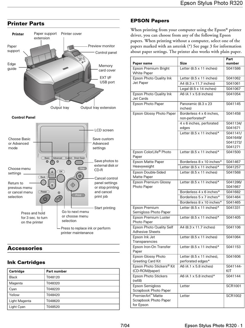
Epson R320 - Stylus Photo Color Inkjet Printer Product information
Kyocera Mita
Kyocera Mita Ecosys FS-6020 Operation guide
LabelTac
LabelTac Pro X user manual
Addressograph
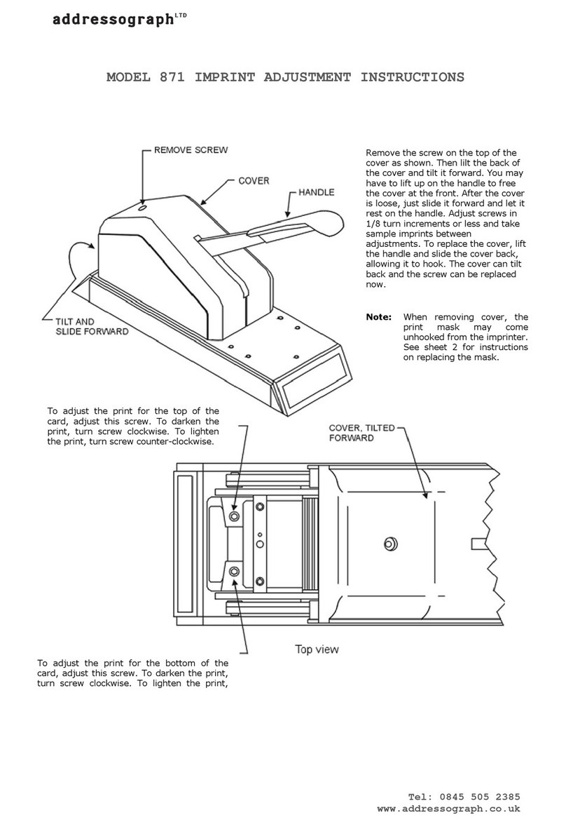
Addressograph 871 Adjustment instructions

