ILLKO REVEXplus USB User manual

Version 5.0-R2 ENG
04/2019
REVEXplus
USER’S
MANUAL
REVEXplus USB

User’s Manual REVEXplus, REVEXplus USB
Copyright © 2006–2019 ILLKO, s.r.o.
2
CONTENTS
1. INTRODUCTION.............................................................................4
1.1. Safety ................................................................................................................................4
1.2. Explanation of symbols on instrument..........................................................................4
1.3. General description.........................................................................................................5
1.4. Applied standards............................................................................................................6
1.5. Symbols used in this manual ..........................................................................................6
2. DESCRIPTION OF THE INSTRUMENT.....................................7
2.1. Front panel and rear panel.............................................................................................7
2.2. Terminals..........................................................................................................................8
2.3. Keyboard and indicators ................................................................................................8
2.4. Included in the set............................................................................................................9
2.5. Optional accessories........................................................................................................9
3. PUTTING INTO OPERATION................................................... 11
3.1. Connecting to mains outlet...........................................................................................11
3.2. Functionality test...........................................................................................................11
4. MEASUREMENTS........................................................................ 13
4.1. Measurement mode control - the
START
key .........................................................13
4.1.1. Measurement mode.......................................................................................................13
4.1.2. HOLD function.............................................................................................................14
4.2. Earth bond 200 mA -
RPE
...........................................................................................14
4.2.1. Test lead resistance compensation...............................................................................14
4.2.2. Earth bond measurement..............................................................................................15
4.3. Insulation resistance -
RISO
........................................................................................16
4.4. Substitute leakage current -
ISUB
...............................................................................17
4.4.1. Protective class I appliances........................................................................................17
4.4.2. Protective class II appliances –substitute touch leakage current...............................18
4.5. PE current during operation -
IPE
and differential leakage current -
I
............19
4.5.1. Protective class I one-phase appliances.......................................................................19
4.5.2. Three-phase and hard-wired appliances -
EXT
.........................................................21
4.6. Touch leakage current -
ID
.........................................................................................22
4.6.1. Protective class II appliances.......................................................................................23
4.6.2. Protective class I appliances........................................................................................24
4.7. Mains voltage and current consumption –
U, I
........................................................25
4.7.1. Mains voltage measurement.........................................................................................26
4.7.2. Current consumption measurement..............................................................................26
4.7.3. Current measurement by means of current clamp -
EXT
..........................................27
4.8. Active power consumption, apparent power consumption and cos
–
P, S
.........28

User’s Manual REVEXplus, REVEXplus USB
Copyright © 2006–2019 ILLKO, s.r.o.
3
4.8.1. Power consumptions and cos
measured in test socket 1...........................................28
4.8.2. Power consumptions and cos
measured by means of current clamp........................29
4.9. Utilization of other external adapters –
EXT
...........................................................30
5. ADDITIONAL INFORMATION................................................. 31
5.1. Displayed messages........................................................................................................31
5.2. Reset of the instrument.................................................................................................32
5.3. Communication with PC (REVEXplus USB only).....................................................32
5.4. Maintenance...................................................................................................................32
5.5. Calibration and service.................................................................................................32
5.6. Ecology ...........................................................................................................................33
6. TECHNICAL SPECIFICATION................................................. 34
6.1. General data...................................................................................................................34
6.2. Functions........................................................................................................................34

User’s Manual REVEXplus, REVEXplus USB
Copyright © 2006–2019 ILLKO, s.r.o.
4
1. INTRODUCTION
1.1. Safety
Read this User’s Manual carefully and completely and follow all instructions
contained therein. Otherwise using of the instrument may be dangerous for
operator, for appliance under test or for the instrument!
Observe the following safety precautions:
•Make sure that the instrument, measuring cables and all other accessories are in flawless
condition, e.g. no damaged insulation, no broken cables or plugs etc.
•The instrument may be powered only from 230 V / 50 ÷ 60 Hz grounded mains outlet,
which is protected with a fuse or circuit breaker with a maximum rating of 16 A.
•Only a trained, skilled person, who is familiar with hazardous voltage operations, can
handle the REVEXplus. Unexpected hazardous voltages can occur at appliance under test
(dangerously charged capacitors etc.).
•It is necessary to respect all safety regulations applicable to particular measurement.
•Test Socket 1 of the REVEXplus must not be used for continuous power supply of
appliance. It is intended for test purposes only; max. test duration is 60 s @ 16A.
•Dangerous voltage or mains voltage may be present on Test Socket 1 during some tests.
•Appliance under test connected to Test Socket 1 of the REVEXplus can be powered by
mains voltage during some tests. The appliance can thus be activated.
•The PE terminal is connected to PE terminal of Test Socket 1. Similarly, the IDterminal
is electrically connected to PE terminal of Test Socket 1. When using the REVEXplus,
do not connect any voltage to the terminals PE or ID. Otherwise there is a danger of
electric shock or damage of the REVEXplus.
•Use only standard or optional accessories supplied with the REVEXplus by your
distributor.
If there is reason to believe that safe operation has become impossible, put
the instrument out of operation and secure it against any unintended operation.
Safe operation must be presumed to be no longer possible, if:
•The instrument does not operate properly any longer.
•The instrument, cables, connectors, plugs or accessories exhibits visible damages.
•The instrument was stored under unfavourable conditions for a long period.
•The instrument was exposed to extraordinary stress caused by transport.
1.2. Explanation of symbols on instrument
Warning concerning a point of danger! Read User’s Manual and observe all precautions!
Protection class (double insulation).
All information, instruction and warnings stated in this User’s Manual are applicable
both for REVEXplus and REVEXplus USB unless otherwise stated.

User’s Manual REVEXplus, REVEXplus USB
Copyright © 2006–2019 ILLKO, s.r.o.
5
1.3. General description
The REVEXplus is professional portable appliance tester with many features packed into very
compact case. The REVEXplus has extraordinary wide scope of use thanks to a lot of optional
accessories, which enables to test practically any portable or hard-wired, one-phase or three-
phase appliance.
FEATURES:
•Earth bond test 200 mA AC.
•Insulation resistance test 500 V DC.
•Measurement of substitute leakage current and touch leakage current.
•Measurement of differential leakage current and touch leakage current, possibility of L-N
reversal in test socket.
•Measurement of PE current during operation and touch leakage current, possibility of L-N
reversal in test socket.
•Functional test of tested appliance: active power consumption (W), apparent power
consumption (VA), current (A), cos φ.
•Mains voltage.
•Measurement of PE current during operation by means of optional current clamp.
•Measurement of differential leakage current by means of optional current clamp.
•Measurement of current by means of optional current clamp.
•Functional test of tested appliance by means of optional current clamp: active power
consumption (W), apparent power consumption (VA), and cos φ.
•Measurement of PE current during operation and differential leakage current of three-phase
portable appliance by means of optional adapters.
•USB communication (REVEXplus USB only).
The REVEXplus has furthermore additional features, which improves the safety of both
operator and the equipment under test:
•Automatic check of dangerous contact voltage on PE of power outlet, from which the
REVEXplus is powered.
•Automatic check, if PE of power outlet (from which the REVEXplus is powered) is
grounded.
•Automatic check of leakage current amplitude of equipment under test.
•Automatic check of external voltage absence during earth bond test.
•The possibility to promptly test the basic functionality of the REVEXplus (built-in normal).

User’s Manual REVEXplus, REVEXplus USB
Copyright © 2006–2019 ILLKO, s.r.o.
6
1.4. Applied standards
* Safety .................................................. EN 61010-1 + A2
* EMC .................................................... EN 55 022
EN 61000-4-2
EN 61000-4-3
EN 61000-4-4
EN 61000-4-5
EN 61000-4-6
EN 61000-4-11
* Equipment for testing, measuring or monitoring of protective measures
EN 61557, part 2
EN 61557, part 4
1.5. Symbols used in this manual
Warning concerning a point of danger!
Read User’s Manual and observe all precautions!
Hint, notice.
--
Control key –meaning in the text is “Press the key”.
(--)
Indicator –it is turned on if particular function is activated.
The (START) indicator can blink or it can be turned on –it depends on
selected measuring mode.
Press and release the relevant key.
Press and release the relevant key repetitively for the purpose of switching
between its several functions.
Press the relevant key and hold it pressed.

User’s Manual REVEXplus, REVEXplus USB
Copyright © 2006–2019 ILLKO, s.r.o.
7
2. DESCRIPTION OF THE INSTRUMENT
2.1. Front panel and rear panel
1
19
20
30
30
234
7 8
31-33 21-29
9-18
6
5
P,S
Ext
START
RR
PE R
I
I
I
I
I
Cal
LOCK
HOLD
ISOPE
PE
SUB
PROTECT
EXT
INV
PE
D
D
U,I
Fig. 1 –Front panel and rear panel
User’s Manual REVEXplus, REVEXplus USB
Copyright © 2006–2019 ILLKO, s.r.o.
8
2.2. Terminals
1Test Socket for connection of tested appliance’s power supply cord.
2ID–touch leakage current test terminal.
3RPE –earth bond test terminal.
4PE –terminal for connecting of exposed conductive part of tested appliance (the
terminal is connected to PE terminal of Test Socket 1).
5Power supply cord.
6RISO+ISUB –insulation resistance / substitute leakage current test terminal.
7EXT INPUT –current clamp / three-phase adapter / other adapters connector.
8USB connector (REVEXplus USB only).
2.3. Keyboard and indicators
Keyboard –each key selects one or more functions
9RPE–Earth bond test.
10 ISUB–Substitute leakage current and touch leakage current.
11 IPE–PE current during operation and touch leakage current.
12 I–Differential leakage current and touch leakage current.
13 ID–Touch leakage current on protective class I appliances.
14 RISO–Insulation resistance.
15 U,I–Mains voltage and appliance’s current.
16 EXT–EXT INPUT for current clamp / three-phase adapter activation.
17 P,S–Active power / apparent power / cos φ.
HOLD–Holding of displayed data.
18 CAL–Test lead resistance compensation on RPE function / basic functionality test.
LOCK- Locks the STARTkey.
19 START–Starts measurement.
Indicators
20 LED display.
(M) −Insulation resistance in
(k) − Insulation resistance in k
() − Earth bond resistance in
24 (mA) −Leakage or touch current in mA.
25 (A) − Supply current of tested application in A.
26 (V) − Mains voltage in V.
27 (W) −Active power in W.
28 (VA) −Apparent power in VA.
29 (cos φ) −cos φ.
•Do not connect any external voltage to any terminal or connector. The only
exception is power supply cord 5 which is intended for powering of the
REVEXplus from 230 V / 50 ÷ 60 Hz mains outlet.
•Max. load on test socket 1 is 16 A, max test duration is 60 s.
•Use original accessories only.

User’s Manual REVEXplus, REVEXplus USB
Copyright © 2006–2019 ILLKO, s.r.o.
9
Status indicators
30 Indicators of active status of the relevant key.
31 (INV) − indicator of L-N reversal in the test socket 1.
32 (EXT) − EXT INPUT is activated.
33 (PROTECT) − Protection (“electronic fuse”) is activated.
2.4. Included in the set
The set includes all accessories necessary for testing of 230 V / 50 ÷ 60 Hz appliances
equipped with movable power supply cord.
The set includes:
•REVEXplus or REVEXplus USB.
•P 2011 –Test lead, black, 2 m.
•P 3011 –Test tip, black.
•User’s manual.
•Calibration certificate.
•USB cable A-B (REVEXplus USB only).
•CD with USB drivers (REVEXplus USB only).
2.5. Optional accessories
Carrying bag
•P 6080 –bag for instrument and some accessories.
It enables measurement with instrument hung around operator’s neck.
Measuring cables and adapters
•P 2012 –Test lead, blue, 2 m.
•P 4012 –Crocodile clip, blue.
•P 4011 –Crocodile clip, black.
•P 3012 –Test tip, blue.
•P 2021 –Extension lead, black, 5 m (for P 2011).
•P 8015 –Three-phase adapter, 16 A socket, 5 contacts.
•P 8016 –Three-phase adapter, 16 A socket, 4 contacts.
•P 8017 –Three-phase adapter, 32 A socket, 5 contacts.
•P 8018 –Three-phase adapter, 32 A socket, 4 contacts.
•P 8030 –Adapter for testing of extension power supply cords.
Special accessories
•P 8010 –Current clamp transformer.
•WELDtest –adapter, which enables measuring of arc welding equipments output
voltage in accordance with EN 60974-4
•PL 2051 –adapter, which enables measuring of medical instruments leakage current.
•P 9080 –Stick-on label with appliance next test term marking.

User’s Manual REVEXplus, REVEXplus USB
Copyright © 2006–2019 ILLKO, s.r.o.
10
Special accessories for REVEXplus USB only
•P 9020 –Barcode reader with PS/2 connector; barcode reader connects to a PC (USB
barcode reader is available, too).
•P 9060 –Stick-on label with barcode.
•P 9092 –Barcode printer PT-E300VP.
•P 9100 –Cartridge TZ-241 for barcode printer; white, width 18 mm, length 8 m.
•P 9101 –Cartridge TZ-231 for barcode printer; white, width 12 mm, length 8 m.
•P 9102 –Cartridge TZ-221 for barcode printer; white, width 9 mm, length 8 m.
User’s Manual REVEXplus, REVEXplus USB
Copyright © 2006–2019 ILLKO, s.r.o.
11
3. PUTTING INTO OPERATION
3.1. Connecting to mains outlet
Use grounded mains outlet only to supply the instrument!
If mains outlet, mains cable, instrument’s case or accessories are damaged, do
not connect the REVEXplus to mains outlet!
The REVEXplus can be powered only from 230 V / 50 ÷ 60 Hz grounded mains, which is
protected with a fuse or circuit breaker with a maximum rating of 16 A.
The instrument is automatically switched on after plugging in to the mains outlet.
Disconnect any equipment under test while connecting/disconnecting the REVEXplus to/from
the mains outlet!
The REVEXplus automatically tests protective PE (ground) pin of mains outlet:
1) If PE connection is inadequate, then the (PROTECT) indicator lights up after the
REVEXplus is plugged in to mains outlet.
2) If dangerous contact voltage arises on PE, then the (PROTECT) indicator lights
up when operator's finger touches the key
START
.
If operator presses the
START
key for all that, the measurement will not start and
message „Prot“ appears on the display.
If test result of ground pin of mains outlet is unsatisfactory, the wrong outlet
must be repaired before you plug in the REVEXplus to mentioned outlet again!
3.2. Functionality test
It can be sometimes difficult to identify that the measuring instrument does not work properly,
especially during leakage current measurement. The REVEXplus has therefore built in the
possibility to promptly test the basic functionality.
Functionality of following functions can be tested:
•Insulation resistance.
•Measurement of substitute leakage current.
•Measurement of differential leakage current (only one L-N polarity).
•Measurement of PE current during operation. (only one L-N polarity).
Disconnect equipment under test before the REVEXplus functionality test!
Functionality test procedure:
•Disconnect equipment under test.
•Use respective key to select the function you are going to test.
•Press the CALkey and release it. The (CAL) indicator lights up.
•Press the STARTkey and release it. The test starts. After it is finished, the result is
displayed and the (CAL) indicator turns off.

User’s Manual REVEXplus, REVEXplus USB
Copyright © 2006–2019 ILLKO, s.r.o.
12
•If you test IPE or Ifunctions and displayed value is close to 0.000 mA, you must repeat
the test once more after switching the L-N polarity by repetitive press and release of
either the IPEor Ikey. The (INV) indicator lights up in such case.
If the value 2.000 M÷ 2.600 Mis displayed, the insulation resistance measurement is
correct.
If the value 0.090 mA ÷ 0.110 mA is displayed, the leakage current measurement is correct.
Contact service if the test results differ from the ones described above.

User’s Manual REVEXplus, REVEXplus USB
Copyright © 2006–2019 ILLKO, s.r.o.
13
4. MEASUREMENTS
4.1. Measurement mode control - the STARTkey
Beginning, process and ending of measurements is controlled by the STARTkey.
START
START START
One measuring cycle
One measuring cycle starts an it is
completed.
START
START START
Continuous measurement
Measurement is in progress until
the STARTkey is released.
1
START
Cal
LOCK
START START
Locking of measurement
Measurement continues though
both keys are released.
2
START
Ending of measurement.
1
START
START START
Holding of displayed data
Measurement is in progress and
displayed result is periodically
updated.
2
P,S
HOLD
START
Measurement is in progress and last
displayed result is displayed.
To cancel the HOLD mode press
and release the [HOLD] key again.
Fig. 2 –Measurement mode control
4.1.1. Measurement mode
The instrument enables to accomplish measurements in following three modes:
•One measuring cycle –after the STARTkey is pressed and released, one measuring
cycle starts and it is completed after few seconds. The result of measurement is displayed.
•Continuous measurement –press the STARTkey; measurement is in progress and
current measured values are displayed until the STARTkey is released.
User’s Manual REVEXplus, REVEXplus USB
Copyright © 2006–2019 ILLKO, s.r.o.
14
•Locking of measurement –press the STARTkey and then press the LOCKkey.
Release both keys. Measurement is in progress and current measured values are
displayed until the STARTkey is again pressed and released.
Measuring process is indicated by (START) indicator.
4.1.2. HOLD function
When measurement is in progress then current measured values are displayed. By press and
release of the HOLDkey the last measured result is displayed on display even if
measurement either ended or continues. The HOLD function is indicated by such way that
blinking of the (START) indicator changes to unremitting light.
HOLD function can be cancelled (measurement is still in progress) by press and release of the
HOLDkey. The (START) indicator then blinks again.
4.2. Earth bond 200 mA - RPE
•Make sure that tested equipment is deenergized –its mains voltage must be
disconnected before starting the measurement!
•Do not connect any external voltage between RPE terminal 3 and either PE in
test socket 1 or PE terminal 4.
•If you are going to test equipment which can be charged to voltage > 25V (e.g.
filter capacitors), discharge it before test!
•In case that external voltage is present on appliance under test, the
(PROTECT) indicator turns on and „Prot“ message is displayed. Such status
is dangerous fault condition; disconnect equipment under test from the
REVEXplus immediately to avoid its damage!
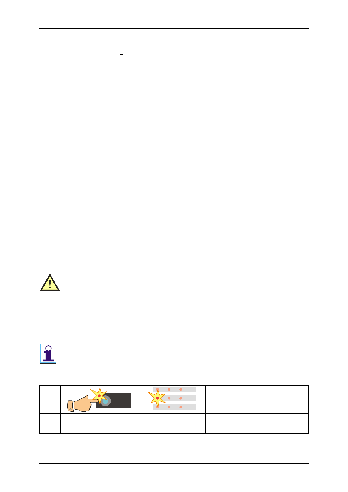
4.2.1. Test lead resistance compensation
Compensation means that the test lead resistance is measured and then automatically
memorized and subtracted from all RPE measurements. The real earth bond resistance
is thus displayed. The compensation constant remains in instrument’s memory even if
the instrument is switched off. And so the lead compensation is valid until new
compensation is carried out.
1
RPE
M
mA
cos
A V
VAW
K
RPE
PE ID
2
Cal
LOCK
3
START
Fig. 3 –Test lead resistance compensation
User’s Manual REVEXplus, REVEXplus USB
Copyright © 2006–2019 ILLKO, s.r.o.
15
•Pres the RPEkey and release it. Symbol „- -“is displayed and indicators (RPE)and
() light up.
•Connect test lead P2011 with test tip P3011 to the RPE terminal.
•Connect test tip of the test lead either to the PE terminal or press it against the ground
pin of the test socket 1. If you use two test leads (which are connected to the PE
terminal and the RPE terminal) then make short-circuit of their test tips.
•Press the CALkey and release it. Now the indicators (CAL), (RPE)and () shine.
•Press the STARTkey and release it. Test lead resistance is shortly displayed, then the
(CAL) indicator turns off and „0.000“ is displayed. Test lead resistance compensation is
finished.
The compensation is effective for test lead resistance < 2 .
If test lead resistance is ≥ 2 and compensation procedure is carried out, compensation is
cancelled and all following displayed results are a sum of earth bond + test lead resistance.
If compensation is active (it means that test lead resistance < 2 was memorized) then the
(CAL) indicator lights up during RPE measurements.
4.2.2. Earth bond measurement
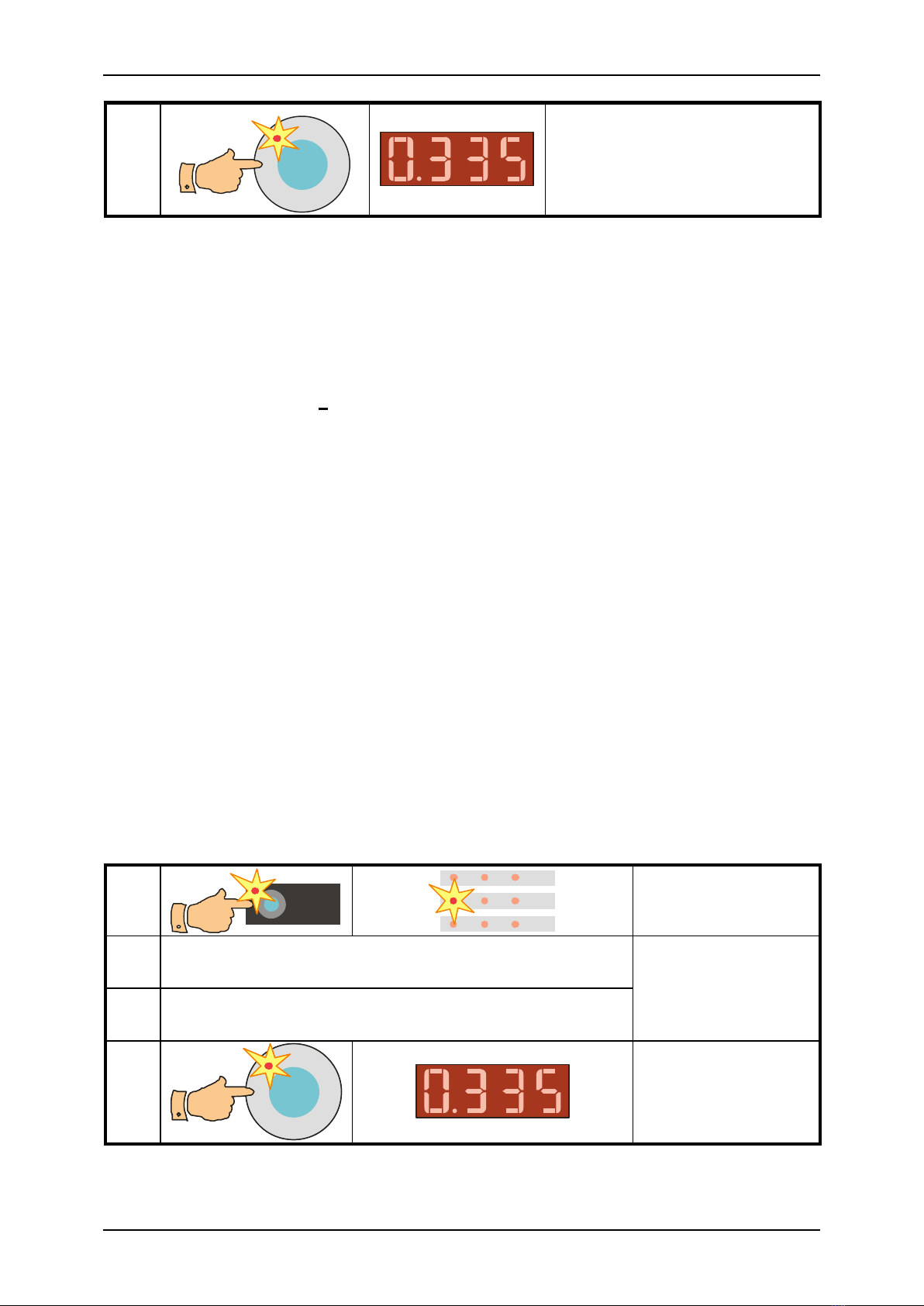
1
RPE
M
mA
cos
A V
VAW
K
Function selection
2
Connect tested appliance
Appliance connecting
3
Press the test tip connected to the RPE terminal
against exposed conductive part of tested appliance
4
START
Cal
LOC K
Measurement
Fig. 4 –Earth bond measurement
Step 1 - preparation for measurement
•Select the RPE function: pres the RPEkey and release it. Symbol „- -“ is displayed and
indicators (RPE)and () light up.
•Connect test lead P2011 with test tip P3011 to the RPE terminal.
•If test lead compensation was not carried out yet, compensate it now –see details in
chapter 4.2.1.
•Connect tested appliance:
-One-phase appliance with movable power supply cord –plug in its mains plug
to test socket 1.
-Three-phase appliance with movable power supply cord –connect PE pin of its
plug to the instrument’s PE terminal by means of optional test lead P2012 +
crocodile clip P4012.
-Hard-wired appliance –firstly disconnect appliance from mains! Connect its
point of PE connection to the instrument’s PE terminal by means of optional
test lead P2012 + crocodile clip P4012.

User’s Manual REVEXplus, REVEXplus USB
Copyright © 2006–2019 ILLKO, s.r.o.
16
Step 2 - measurement
•Press test tip against exposed conductive part of tested appliance.
•Press the STARTkey; measurement starts to run (see chapter 4.1. for measurement
control details). Measurement is indicated by the (START) indicator. If the (CAL)
indicator lights on during measurement, it means that test lead resistance is
compensated (see chapter 4.2.1. for details).
•After finishing of measurement (the (START) indicator turns off) the lowest measured
value of earth bond resistance is displayed. If only „1“ is displayed (see chapter 5.1 for
details) it means that measured earth bond resistance is higher than maximal value
which can be measured by the REVEXplus.
4.3. Insulation resistance - RISO
•Make sure tested appliance is deenergized –its mains voltage must be
disconnected before starting of measurement!
•Do not touch exposed conductive parts of tested appliance while measurement
is in progress –RISK OF ELECTRC SHOCK! Measurement in progress is
indicated by the (START) indicator.
•Do not disconnect test leads while measurement is in progress or immediately
after finishing the measurement. Capacitive component of tested appliance can
be charged to voltage up to 750 V; after the key STARTis released, this
voltage is automatically discharged! If the capacitive component would be so
extraordinary high that the discharging circuitry in the REVEXplus would not
be able to discharge it to voltage < 50 V, the message „Prot“ would be
displayed. Tested appliance must be disconnected from the instrument in this
case and its capacitance must be discharged by another alternative safe
method.
In case that external voltage is present on tested appliance, measurement will not be
carried out. Indicator (PROTECT) turns on and message „Prot“ is displayed.
1
RISO
M
mA
cos
A V
VAW
K
Function selection
2
Connect tested appliance; its mains
switch must be switched on
Appliance connecting
3
START
Measurement
Fig. 5 –Insulation resistance measurement
Step 1 - preparation for measurement
•Select the RISO function: pres the RISOkey and release it. Symbol „- -“ is displayed
and indicators (RISO)and (M) light up.
•Connect tested appliance:
User’s Manual REVEXplus, REVEXplus USB
Copyright © 2006–2019 ILLKO, s.r.o.
17
-One-phase appliance with movable power supply cord –plug in its mains plug
to test socket 1.
-Three-phase appliance with movable power supply cord –connect PE pin of its
plug to the instrument’s PE terminal by means of optional test lead P2012 +
crocodile clip P4012. Then connect remaining current-carrying conductors by
means of test lead P2011 + test tip P3011 to the instrument’s RISO + ISUB
terminal (placed on rear panel).
-Hard-wired appliance –firstly disconnect appliance from mains! Connect its
point of PE connection to the instrument’s PE terminal by means of optional
test lead P2012 + crocodile clip P4012. Then connect remaining current-
carrying conductors by means of test lead P2011 + test tip P3011 to the
instrument’s RISO + ISUB terminal (placed on rear panel).
Step 2 - measurement
•Switch on tested appliance’s mains switch.
•Press the STARTkey; measurement starts to run (see chapter 4.1. for measurement
control details). Measurement is indicated by the (START) indicator. It is
recommended to hold the STARTkey pressed 5-10 s (or even longer if displayed
result is not stabilized) - the influence of tested appliance’s internal capacitance can be
eliminated by this method.
•After finishing of measurement (the (START) indicator turns off) the last measured
value of insulation resistance is displayed. At the same time either indicator
(M) or (k) lights up and so the unit of measured insulation resistance is determined.
If only „1“ is displayed (see chapter 5.1 for details) it means that measured insulation
resistance is higher than maximal value which can be measured by the REVEXplus.
4.4. Substitute leakage current - ISUB
•Make sure tested appliance is deenergized –its mains voltage must be
disconnected before starting of measurement!
•Firstly earth bond resistance (chapter 4.2.) must be tested; it is recommended
to test insulation resistance, too (chapter 4.3.). Then you can execute
substitute leakage current measurement!
•Do not touch exposed conductive parts of tested appliance while measurement
is in progress –RISK OF ELECTRC SHOCK! Measurement in progress is
indicated by the (START) indicator.
Test voltage is max. 230 V / 50 ÷ 60 Hz, short circuit current is about 3.5 mA.
4.4.1. Protective class I appliances
1
ISUB
M
mA
cos
A V
VA
W
K
Function selection
2
Connect tested appliance; its mains
switch must be switched on
Appliance connecting
User’s Manual REVEXplus, REVEXplus USB
Copyright © 2006–2019 ILLKO, s.r.o.
18
3
START
Measurement
Fig. 6 –Substitute leakage current measurement
Step 1 - preparation for measurement
•Select the ISUB function: pres the ISUBkey and release it. Symbol „- -“ is displayed
and indicators (ISUB)and (mA) light up.
•Connect tested appliance:
-One-phase appliance with movable power supply cord –plug in its mains plug
to test socket 1.
-Three-phase appliance with movable power supply cord –connect PE pin of its
plug to the instrument’s PE terminal by means of optional test lead P2012 +
crocodile clip P4012. Then connect remaining current-carrying conductors by
means of test lead P2011 + test tip P3011 to the instrument’s RISO + ISUB
terminal (placed on rear panel).
-Hard-wired appliance –firstly disconnect appliance from mains! Connect its
point of PE connection to the instrument’s PE terminal by means of optional
test lead P2012 + crocodile clip P4012. Then connect remaining current-
carrying conductors by means of test lead P2011 + test tip P3011 to the
instrument’s RISO + ISUB terminal (placed on rear panel).
Step 2 –measurement
•Switch on tested appliance’s mains switch.
•Press the STARTkey; measurement starts to run (see chapter 4.1. for measurement
control details). Measurement is indicated by the (START) indicator.
•After finishing of measurement (the (START) indicator turns off) the last measured
value of substitute leakage current is displayed.
4.4.2. Protective class II appliances –substitute touch leakage current
1
ISUB
M
mA
cos
A V
VA
W
K
Function selection
2
Connect tested appliance; its mains switch must be
switched on
Appliance connecting
3
Press the test tip connected to the IDterminal
against exposed conductive part of tested appliance
4
STARTSTART
Measurement
Fig. 7 –Substitute touch leakage current measurement

User’s Manual REVEXplus, REVEXplus USB
Copyright © 2006–2019 ILLKO, s.r.o.
19
Step 1 - preparation for measurement
•Select the ISUB function: pres the ISUBkey and release it. Symbol „- -“ is displayed
and indicators (ISUB)and (mA) light up.
•Connect tested appliance:
-One-phase class II appliance with movable power supply cord –plug in its
mains plug to test socket 1.
•Connect test lead P2011 + test tip P3011 to the instrument’s ID terminal.
•Switch on tested appliance’s mains switch.
Step 2 –measurement
•Press test tip against exposed conductive part of tested appliance.
•Press the STARTkey; measurement starts to run (see chapter 4.1. for measurement
control details). Measurement is indicated by the (START) indicator.
•After finishing of measurement (the (START) indicator turns off) the last measured
value of substitute touch leakage current is displayed.
4.5. PE current during operation - IPEand differential leakage current -
I
4.5.1. Protective class I one-phase appliances
WARNING - DANGER!
•If test voltage is present in Test socket 1 –it is indicated by the (START)
indicator, then tested equipment starts to run after its mains switch is
switched on! Take into consideration all safety warnings, referred to
equipment under test!
•Do not touch exposed conductive parts of tested object after mains switch is
switched on!
•Firstly earth bond resistance (chapter 4.2.) must be tested; it is recommended
to test insulation resistance if it is possible, too (chapter 4.3.). Then you can
execute leakage current measurement!
•Equipment under test must be isolated from ground (from the earth
potential) during measurement of IPE!
•Test Socket 1 of the REVEXplus must not be used for continuous power
supply of appliance! It is intended for test purposes only; max. test duration
is 60 s @ 16A.
The REVEXplus is equipped with electronic checking of excessive leakage current
during measurement. If leakage current exceeds limit value about 12 mA, then mains
voltage is disconnected from test socket 1. This status is indicated by displaying
„Prot“ message; the indicator (PROTECT) turns on, too.
1
IPE
M
mA
cos
A V
VA
W
K
PROTECT
EXT
INV
Function selection
2
Connect tested appliance
Connect tested appliance to
test socket 1

User’s Manual REVEXplus, REVEXplus USB
Copyright © 2006–2019 ILLKO, s.r.o.
20
3
START
Cal
LOCK
STARTSTART STARTSTART
Test socket 1energizing
(Locking of the START
key)
4
Switch on tested
appliance
Measurement
5
Switch off tested appliance
End of measurement
6
START
Test socket 1deenergizing
(Unlocking of the START
key)
7
IPE
M
mA
cos
A V
VA
W
K
PROTECT
EXT
INV
L-N reversal in test socket 1
8
START
Cal
LOCK
START START
Test socket 1energizing
(Locking of the START
key)
9
Switch on tested
appliance
Measurement
10
Switch off tested appliance
End of measurement
11
START
Test socket 1deenergizing
(Unlocking of the START
key)
Fig. 8 –Leakage current measurement
Step 1 - preparation for measurement
•Select the IPE function or the Ifunction: pres either the IPEkey or the Ikey and
release it. Symbol „- -“ is displayed and indicators either (IPE)or (I)and (mA) light
up.
•Connect tested appliance: plug in its mains plug to test socket 1.
Step 2 –measurement with L-N default
•Press and release either the IPEor the Ikey. If the indicator (INV) lights up, then
press and release corresponding key once more in order to turn off the indicator (INV).
•Press the STARTkey. It is recommended to lock the measurement - press the
STARTkey and then press the LOCKkey. Release both keys. The presence of
Table of contents
Other ILLKO Test Equipment manuals


