ILLKO ESC 2051 User manual

ESC-03/05-R2

User’s Manual ESC 2051
Copyright © 2004 ILLKO s.r.o. 2
CONTENTS
1. INTRODUCTION ...........................................................................4
1.1. Safety .............................................................................................................................. 4
1.2. Explanation of symbols .................................................................................................4
1.3. General description ....................................................................................................... 4
1.4. Applied standards.......................................................................................................... 5
2. DESCRIPTION OF THE INSTRUMENT ...................................6
2.1. Front panel and rear panel........................................................................................... 6
2.2. Terminals........................................................................................................................ 6
2.3. eyboard ........................................................................................................................ 7
2.4. Included in the set.......................................................................................................... 8
2.5. Optional accessories ...................................................................................................... 8
3. PERFORMING MEASUREMENTS ............................................9
3.1. Connecting to mains outlet ........................................................................................... 9
3.2. PIN code ......................................................................................................................... 9
3.3. Functionality test ......................................................................................................... 10
4. MEASUREMENTS .......................................................................11
4.1. Earth bond 200 mA ..................................................................................................... 11
4.1.1. Protective class I equipments equipped with mains plug........................................... 11
4.1.2. Protective class I hard-wired and three-phase equipments ....................................... 12
4.2. Voltage drop 10 A and earth bond 10 A.................................................................... 13
4.2.1. Protective class I machines equipped with mains plug .............................................. 14
4.2.2. Protective class I three-phase and hard-wired machines .......................................... 16
4.2.3. Earth-bond.................................................................................................................. 18
4.3. Insulation resistance.................................................................................................... 19
4.3.1. Protective class I equipments equipped with mains plug........................................... 20
4.3.2. Protective class II equipments equipped with mains plug.......................................... 21
4.3.3. Protective class I three-phase and hard-wired equipments ....................................... 22
4.4. Substitute leakage current .......................................................................................... 24
4.4.1. Protective class I equipments equipped with mains plug........................................... 24
4.4.2. Protective class II equipments equipped with mains plug.......................................... 25
4.4.3. Protective class I three-phase and hard-wired equipments ....................................... 26
4.5. PE current during operation and touch leakage current ........................................ 27
4.5.1. Protective class I equipments equipped with mains plug........................................... 27
4.5.2. Protective class II equipments equipped with mains plug.......................................... 30
4.5.3. Protective class I three-phase and hard-wired equipments ....................................... 32
4.5.4. Protective class II hard-wired equipments................................................................. 34

User’s Manual ESC 2051
Copyright © 2004 ILLKO s.r.o. 3
4.6. Differential leakage current and touch leakage current.......................................... 35
4. .1. Protective class I equipments equipped with mains plug........................................... 35
4. .2. Protective class II equipments equipped with mains plug.......................................... 38
4.7. Leakage current by means of current clamp ............................................................ 40
4.7.1. PE current during operation and differential leakage current .................................. 40
4.8. Leakage current by means of three-phase adapter .................................................. 42
4.8.1. PE current during operation and differential leakage current .................................. 42
4.9. Tested equipment power and current........................................................................ 43
4.9.1. Power measurement of equipments equipped with mains plug.................................. 43
4.9.2. Current ....................................................................................................................... 44
4.10. Temperature............................................................................................................... 46
4.11. Revolution .................................................................................................................. 46
5. MENU .............................................................................................47
5.1. Utilization and structure of MENU ........................................................................... 47
5.1.1. How to enter MENU and to move in MENU.............................................................. 47
5.1.2. The MENU structure .................................................................................................. 47
5.2. Description of MENU items........................................................................................ 48
5.3. Memory......................................................................................................................... 50
5.3.1. Buffer .......................................................................................................................... 52
5.3.2. Main memory.............................................................................................................. 53
6. ADDITIONAL INFORMATION ................................................57
6.1. Displayed messages...................................................................................................... 57
6.2. Reset of the instrument ............................................................................................... 58
6.3. Leakage current and touch leakage current measurement methods...................... 58
6.4. Maintenance................................................................................................................. 61
6.5. Calibration ................................................................................................................... 62
6.6. Service........................................................................................................................... 62
7. TECHNICAL SPECIFICATION ................................................63
7.1. General data................................................................................................................. 63
7.2. Functions ...................................................................................................................... 63
User’s Manual ESC 2051
Copyright © 2004 ILLKO s.r.o. 4
1. INTRODUCTION
1.1. Safety
Read this instruction manual carefully and completely and follow all
instructions contained therein. Otherwise using of the instrument may be
dangerous for the operator, for equipment under test or for the instrument!
Observe the following safety precautions:
•Make sure that the instrument, measuring cables and all other accessories are in fla less
condition, e.g. no damaged insulation, no broken cables or plugs etc.
•The instrument may be po ered only from 230 V / 50 Hz grounded mains outlet, hich
is protected ith a fuse or circuit breaker ith a maximum rating of 16 A.
•Only a trained, skilled person, ho is familiar ith hazardous voltage operations, can
handle the ESC 2051. Unexpected hazardous voltages can occur at appliance under test
(dangerously charged capacitors etc.).
•It is necessary to respect all safety regulations applicable to particular measurement.
•Test Socket 1 of the ESC 2051 must not be used for continuous po er supply of
appliance. It is intended for test purposes only; max. test duration is 30 min. @ 16A.
•Dangerous voltage or mains voltage may be present on Test Socket 1 during some tests.
•Appliance under test connected to Test Socket 1 of the ESC 2051 can be po ered by
mains voltage during some tests. The appliance can thus be activated.
•Use only standard or optional accessories supplied ith the ESC 2051.
The ESC 2051 must not be used:
•If it no longer functions properly.
•If instrument, cables, connectors, plugs or other accessories is damaged.
•After extraordinary stresses (due to transport, unsuitable storage conditions etc.).
1.2. Explanation of symbols
Warning concerning a point of danger! Read User’s Manual and observe all precautions!
Hint, notice.
Protection class (double insulation).
1.3. General description
The ESC 2051 is professional portable appliance tester ith many features packed into very
compact case. The ESC 2051 has extraordinary ide scope of use thanks to a lot of optional
accessories, hich enables to test practically any portable or hard- ired, one-phase or three-
phase appliance.

User’s Manual ESC 2051
Copyright © 2004 ILLKO s.r.o. 5
FEATURES:
•Earth bond test 200 mA and 10 A AC and earth bond voltage drop at 10 A AC.
•Insulation resistance test 500 V / 250 V / 100 V DC.
•Measurement of substitute leakage current.
•Measurement of touch leakage current ith 2 kΩprobe.
•Measurement of differential leakage current, possibility to exchange L/N in test socket.
•Measurement of PE current during operation, possibility to exchange L/N in test socket.
•Functional test – po er consumption of tested appliance. Three-phase and hard- ired
appliances functional test by means of optional clamp.
•Measurement of differential leakage current by means of optional clamp.
•Measurement of PE current during operation and differential leakage current of three-
phase portable appliance by means of optional adapters - 16 A and 32 A socked.
•Temperature – type K probe or infrared contact less probe ith type K output signal.
•Rotation – contact less probe.
•Memory for results of about 900 measurements.
•RS 232 communication, PC soft are.
•Optional barcode reader.
The ESC 2051 has furthermore additional features, hich improves the safety of both operator
and the equipment under test:
•Automatic test of dangerous contact voltage on PE of po er outlet, from hich the ESC
2051 is po ered.
•Automatic test, if PE of po er outlet (from hich the ESC 2051 is po ered) is grounded.
•Automatic test of leakage current of equipment under test.
•The possibility to promptly test the basic functionality of the ESC 2051 (built-in normal)
•Only authorized person(s) can operate the ESC 2051, if PIN function is activated.
1.4. Applied standards
* Safety ................................................... EN 61010-1 + A2
* EMC .................................................... EN 55 022
EN 61000-4-2
EN 61000-4-3
EN 61000-4-4
EN 61000-4-5
EN 61000-4-6
EN 61000-4-11
*
Equipment for testing, measuring or monitoring of protective measures
EN 61557, part 2
EN 61557, part 4
User’s Manual ESC 2051
Copyright © 2004 ILLKO s.r.o. 6
2. DESCRIPTION OF THE INSTRUMENT
2.1. Front panel and rear panel
SONDE
ESC 2051
PRÜFDOSE / TEST SOCKET
START
9
7
5
ENTER
DEL
CAL
ESC
1
0
2
3
4
6
8
R
U/R
200mA
∆
10A
R
P
ISO
VA
SAVE
I
LEAK
I
PE
I
PE INV.
PE
PE
I
DIFF.
DEL
I
DIFF. INV.
LOAD
MENU
R
TEMP.
PE
RI
ISO LEAK
/
17 - 19
21
22
23
11 - 16
6
25
24
4
3
5
1
2
7
9
10
8
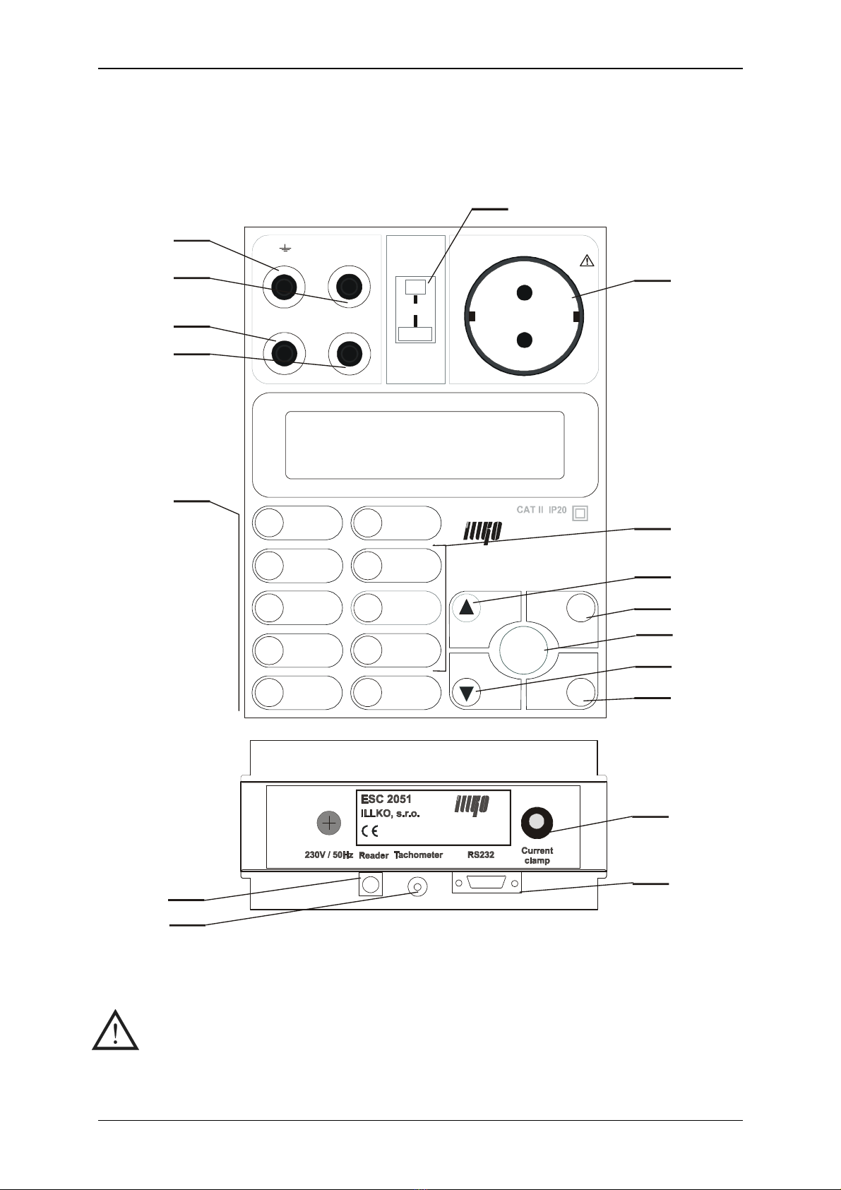
Fig. 1
2.2. Terminals
•Do not connect any external voltage to barcode reader, thermometer probe
and RPE connectors.
•Max. load on TEST SOC ET is 3600 W, max. test duration is 30 min.
•Use original accessories only.

User’s Manual ESC 2051
Copyright © 2004 ILLKO s.r.o. 7
Legend:
1Test socket 230V / 16A
2TEMP. – thermometer probe connector
3 – test terminal, hich is connected to PE ire of test socket
4SONDE – touch leakage current test terminal
5RPE – continuity / earth bond test terminal
6RISO / ILEAK – insulation resistance / substitute leakage current test terminal
7 RS 232 connector for PC connection
8 Barcode reader connector
9 Current clamp / three-phase adapter connector
10 Rotation sensor connector
2.3. Keyboard
Legend:
numerical / function:
11 number 0/ Earth bond test 200 mA
12 number 1/ Earth bond test 10 A
13 number 2/ Insulation resistance test
14 number 3/ Substitute leakage current
15 number 4/ PE current, touch leakage current
16 number 5/ PE current, touch leakage current, L/N exchanged
17 number 6/ Differential leakage current, touch leakage current
18 number 7/ Differential leakage current, touch leakage current, L/N exchanged
19 number 8/ Po er consumption
20 number 9/ Menu
memory:
17 DEL – to delete selected record from instrument’s main memory
18 LOAD – to load selected record from instrument’s main memory to the buffer
19 SAVE – to save the record from the buffer to instrument’s main memory
other:
21 START – press it to start measurement. Release it to finish measurement.
(Locking of the START key - DEL key must be pressed simultaneously).
The ESC 2051 functionality test (CAL key must be pressed simultaneously).
22 ▲ - to select parameters up ardly / to erase character (DEL) / Locking of the
START key - DEL key must be pressed simultaneously.
23 ▼ - to select parameters do n ardly / to calibrate the resistance of the test leads
(CAL) / HOLD (to “freeze” the result on display)
24 ESC - to escape some started procedure
25 ENTER - to confirm ne setting

User’s Manual ESC 2051
Copyright © 2004 ILLKO s.r.o. 8
2.4. Incl ded in the set
•The ESC 2051
•P 2011 - Test lead, black, 2 m
•P 4011 - Crocodile clip, black
•P 3011 - Test tip, black
•Calibration certificate
•Instruction manual
2.5. Optional accessories
•P 2012 - Test lead, blue, 2 m
•P 4012 - Crocodile clip, blue
•P 3012 - Test tip, blue
•P 2021 - Extension lead, black, 5 m (for P 2011)
•P 6061 - Carrying bag
•P 7011 - Simple PC soft are RVie for Windo s 98SE / 2000 / XP
•P 8015 - Three-phase adapter, 16 A socket, 5 contacts
•P 8016 - Three-phase adapter, 16 A socket, 4 contacts
•P 8017 - Three-phase adapter, 32 A socket, 5 contacts
•P 8018 - Three-phase adapter, 32 A socket, 4 contacts
•P 8010 - Clamp transformer
•P 9030 - Temperature probe (K type)
•P 9050 - Rotation sensor
•P 9020 - Barcode reader
•P 9070 - RS 232 cable
•P 9060 - Barcode labels
•PL 2051 - Option for measuring of leakage current of medical instruments
User’s Manual ESC 2051
Copyright © 2004 ILLKO s.r.o. 9
3. PERFORMING MEASUREMENTS
3.1. Connecting to mains o tlet
Use grounded mains outlet only to supply the instrument!
If mains outlet, mains cable, instrument’s case or accessories are damaged, do
not connect the ESC 2051 to mains outlet!
The ESC 2051 can be po ered only from 230 V / 50 Hz grounded mains, hich is protected
ith a fuse or circuit breaker ith a maximum rating of 16 A.
The instrument is automatically s itched on after plugging in to the mains outlet.
Disconnect any equipment under test hile connecting the ESC 2051 to the mains outlet!
The ESC 2051 automatically tests protective (ground) pin of mains outlet; the test is
done always, when operator's finger touches button START. Make sure to stand on
non-isolated floor, while carrying out the test, otherwise test result may be wrong.
If the test result of ground pin is unsatisfactory, message „PE error !!!“ appears on
the display and further measurement is not possible. In such case disconnect the
ESC 2051 from faulty mains outlet and connect it to non-defective mains outlet.
If test result of ground pin of mains outlet is unsatisfactory, the wrong outlet
must be repaired before you plug in the ESC 2051 to mentioned outlet again!
3.2. PIN code
Only authorized person(s) can operate the ESC 2051, if PIN code function is activated.
In such case operator must enter valid PIN code after the instrument po ers up, other ise
instrument’s keyboard is locked.
PIN code can consists of max four digits. Code 0000 deactivates PIN code function.
If PIN code function is activated, proceed as follo s:
Step 1
•Connect mains cable of the ESC 2051 to grounded mains outlet 230 V / 50 Hz.
•Message „PIN:“ is displayed.
Step 2
•Enter valid PIN by means of numerical keyboard. Entered numbers are displayed as
„∗“.
•Press the ENTER key and release it to confirm entered PIN. The instrument is ready
for use no .
If entered PIN is not valid, the keyboard stops to respond and message „Block…“ is
displayed.
The ESC 2051 must be disconnected from mains outlet and plugged in again to continue.
Activation of PIN code function and entering of PIN code:
User’s Manual ESC 2051
Copyright © 2004 ILLKO s.r.o. 10
•Press the MENU key; the main menu is opened.
•Use ▲and ▼keys to select submenu „Set-up“ and press ENTER.
•Use ▲and ▼keys to select item „Change PIN“ and press ENTER.
•Use 0÷9keys to enter PIN code (max. four digits) and press ENTER. Even no digit
can be set as PIN (it means only ENTER is to be pressed)!
•Press the ESC key and release it (repeatedly) until you abandon (sub)menus.
Deactivation of PIN code function:
•Press the MENU key; the main menu is opened.
•Use ▲and ▼keys to select submenu „Set-up“ and press ENTER.
•Use ▲and ▼keys to select item „Change PIN“ and press ENTER.
•Use 0key to enter 0000 and press ENTER.
•Press the ESC key and release it (repeatedly) until you abandon (sub)menus.
If you forget PIN, the instrument must be sent to service!
Therefore we advice you to notice your PIN carefully!
3.3. F nctionality test
It can be difficult to identify that the instrument is damaged, especially during leakage current
measurement. The ESC 2051 has therefore built in the possibility to promptly test the basic
functionality.
Functionality of follo ing functions can be tested:
•Insulation resistance
•Measurement of substitute leakage current
•Measurement of differential leakage current
•Measurement of PE current during operation
Disconnect equipment under test before the ESC 2051 functionality test!
Functionality test procedure:
•Disconnect equipment under test.
•Use respective key to select the function you are going to test.
•Press and hold ▼key and simultaneously press and release the START key. Then
release ▼key.
If the value 1.00 mA ± 10% is displayed the leakage current measurement is correct*.
If the value 0.20 MΩ÷ 0.26 MΩis displayed, the insulation resistance measurement is
correct.
*If you test PE current measurement functionality IPE and displayed value is close to
0.00 mA, you must repeat the test ith selected function IPE INV. The same notice is
valid for differential leakage current functionality test.
If the value 1.00 mA ± 10% is displayed, the leakage current measurement is correct.
Contact service in case that the result(s) of the test differs from the results described above.
User’s Manual ESC 2051
Copyright © 2004 ILLKO s.r.o. 11
4. MEASUREMENTS
4.1. Earth bond 200 mA
•Make sure tested equipment is deenergized – its mains voltage must be
disconnected before starting the measurement!
•If you are going to test equipment which can be charged to voltage > 25V (e.g.
filter capacitors), discharge it before test!
•In case that external voltage is present at equipment under test, the
measurement will not be carried out after pressing the START key and the
message „Voltage on input“ will be displayed. Therefore it is important to
connect test leads to equipment under test first and to press the START key
afterwards; otherwise the function of protective circuitry in the ESC 2051
could be impaired!
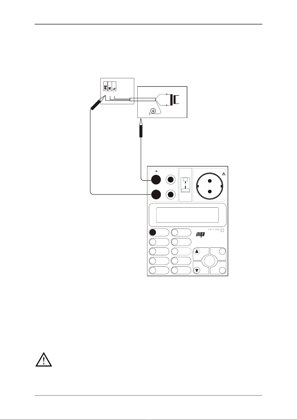
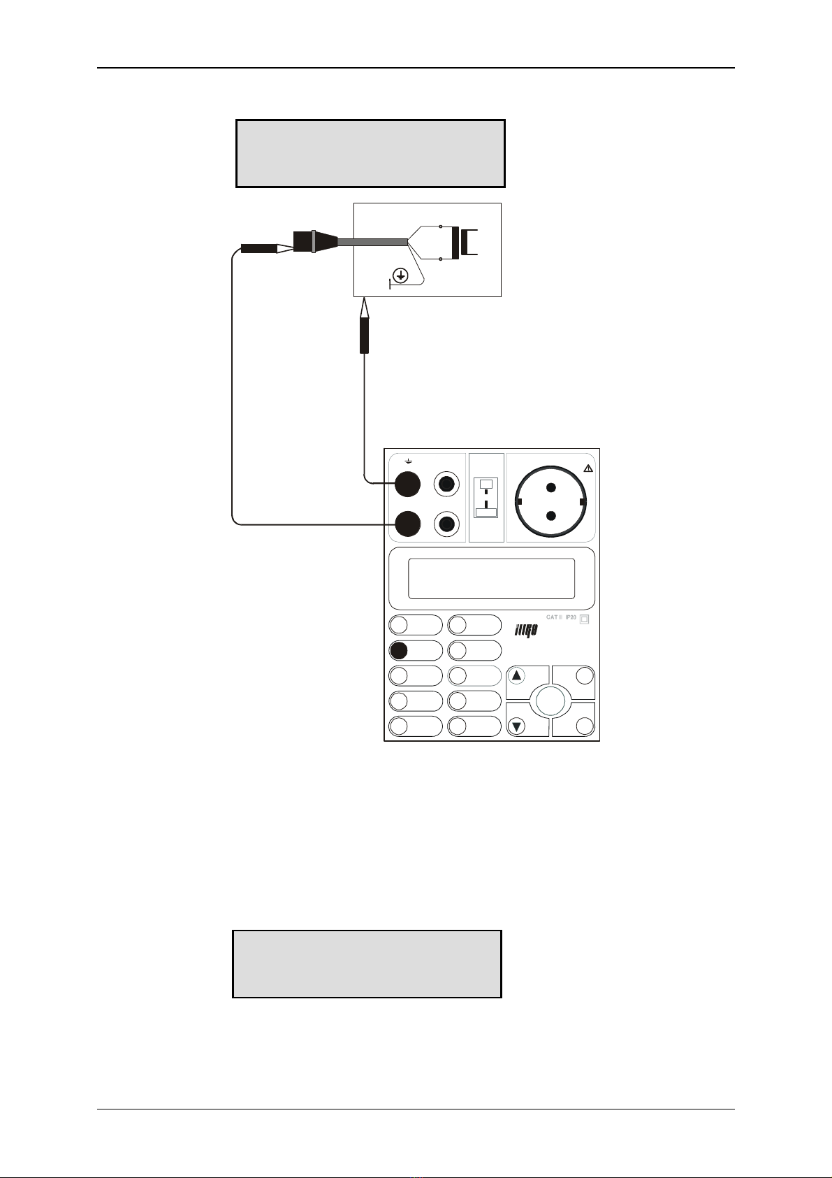
4.1.1. Protective class I equipments equipped with mains plug
Step 1
•Press the RPE 200mA key and release it to select 200mA earth bond function.
•Either result of last measurement or „---“ ill be displayed.
Step 2
•Connect test lead P 2011 ith test tip P 3011 to RPE terminal.
•Connect test tip of the test lead either to terminal or press it against the ground pin
of Test socket 1.
•Press the START key and release it. Test lead resistance is displayed.
•Press the CAL key and release it. The test lead resistance is memorized and it ill be
automatically subtracted from test results. „00.00 Ω“ and „C“ is displayed, indicating
the compensation as accomplished. Test lead compensation is valid until the test lead
is replaced or the ESC 2051 is s itched off.
Step 3
•Plug in the mains cable of equipment under test to Test socket 1 (Fig. 2).
•Press test tip against exposed metallic part of equipment under test. Press the START
key to start measurement. Measurement starts to run and the results are currently
displayed. Symbol „“ indicates, that measurement is running.
•Release the START key again to stop the measurement. The lo est measured
resistance ill be displayed. This value is automatically ritten to the buffer, too.
RPE200mA
---
RPE200mA
00.00 Ω
C

User’s Manual ESC 2051
Copyright © 2004 ILLKO s.r.o. 12
SO N DE
ESC 2051
PR ÜF D O SE / TE S T SO C KE T
START
9
7
5
EN T ER
DEL
CAL
ES C
1
0
2
3
4
6
8
R
U/R
200mA
∆
10A
R
P
ISO
VA
SAVE
I
LEAK
I
PE
I
PE INV.
PE
PE
I
DIFF.
DEL
I
DIFF. INV.
LOAD
MENU
R
T EMP.
PE
RI
IS O LEA K
/
Fig. 2
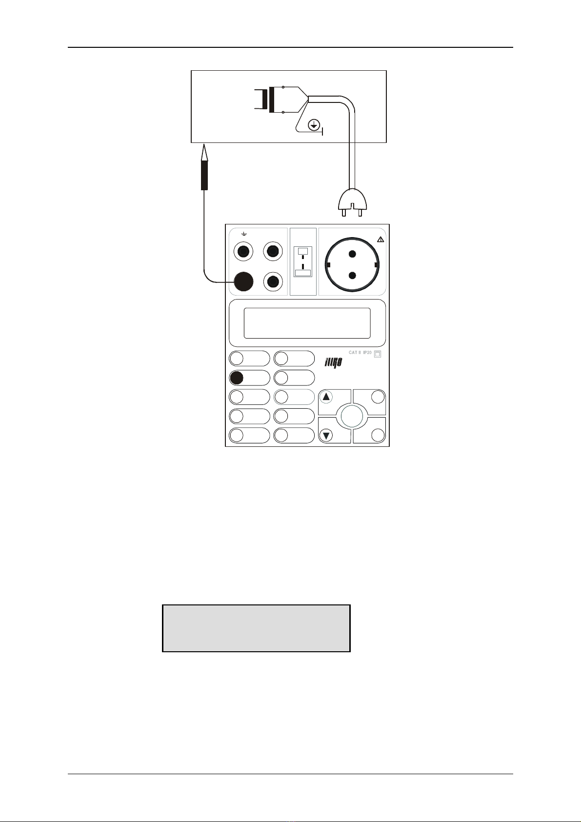
4.1.2. Protective class I hard-wired and three-phase equipments
Step 1
•Press the RPE 200mA key and release it to select 200mA earth bond function.
•Either result of last measurement or „---“ ill be displayed.
Step 2
•Connect test lead P 2011 ith test tip P 3011 to RPE terminal and test lead P 2012 ith
test tip P 3012 (or ith crocodile clip P 4012) to terminal.
•Short circuit both test tips in order to calibrate test leads resistance.
•Press the START key and release it. Test leads resistance is displayed.
•Press the CAL key and release it. The test leads resistance is memorized and it ill be
automatically subtracted from test results. „00.00 Ω“ and „C“ is displayed, indicating
the compensation as accomplished. Test leads compensation is valid until the test
leads are replaced or the ESC 2051 is s itched off.
User’s Manual ESC 2051
Copyright © 2004 ILLKO s.r.o. 13
Step 3
•Disconnect equipment under test from mains!
•Press one test tip against earthing contact of equipment under test (or connect it to
protective contact of three-phase plug). Press another test tip against exposed metallic
part of equipment under test (Fig. 3).
SONDE
ESC 2051
PRÜFDOSE / TEST SOCKET
STAR T
9
7
5
ENTER
DEL
CAL
ESC
1
0
2
3
4
6
8
R
U/R
200mA
∆
10A
R
P
ISO
VA
SAVE
I
LEAK
I
PE
I
PE INV.
PE
PE
I
DIFF.
DEL
I
DIFF. I NV.
LOAD
MENU
R
TEMP.
PE
RI
ISO LEAK
/
Fig. 3
•Press the START key to start measurement. Measurement starts to run and the results
are currently displayed. Symbol „“ indicates, that measurement is running.
•Release the START key again to stop the measurement. The lo est measured
resistance ill be displayed. This value is automatically ritten to the buffer, too.
4.2. Voltage drop 10 A and earth bond 10 A
•Make sure tested equipment is deenergized – its mains voltage must be
disconnected before starting the measurement!
•If you are going to test equipment which can be charged to voltage > 25V (e.g.
filter capacitors), discharge it before test!
User’s Manual ESC 2051
Copyright © 2004 ILLKO s.r.o. 14
•In case that external voltage is present at equipment under test, the
measurement will not be carried out after pressing the START key and the
message „Voltage on input“ will be displayed. Therefore it is important to
connect test leads to equipment under test first and to press the START key
afterwards; otherwise the function of protective circuitry in the ESC 2051
could be impaired!
•In case of too hot internal circuitry of the ESC 2051 „Temp” message will be
displayed. Audible tone beep) will be generated, too. In such case please wait, until
internal temperature decreases. Other functions of the ESC 2051 are not affected.
•The ESC 2051 includes audible indication of test current amplitude. If test current
falls under 10 A during measurement, the device will beep shortly after displaying
result. If test current falls under 3 A, the measurement will be stopped.
4.2.1. Protective class I machines equipped with mains plug
Step 1
•Press the ∆U/RPE 10A key and release it to select 10A voltage drop function (press
and release it again to select 10A earth bond function).
•Either result of last measurement or „---“ ill be displayed. The set value of cross-
section of protective conductor ill be displayed, too.
Step 2
If you need to change timer setting, proceed as follo s:
•Press the MENU key; the main menu is opened.
•Use ▲and ▼ keys to select submenu „Set-up“ and press ENTER.
•Use ▲and ▼ keys to select item „Timer RPE 10A“ and press ENTER.
•Use DEL key to erase current setting.
•Use 0÷9keys to enter required ne setting (1 ÷ 15 s; if you set value to 0, the
measurement ill be running continually until you either disconnect test leads or
internal circuitry overheats) and press ENTER. Once the value is set it remains in
instrument’s memory even if it is disconnected from mains.
•Press the ESC key and release it (repeatedly) until you abandon (sub)menus.
Step 3
If you need to change protective conductor cross-section setting, proceed as follo s:
•Press the MENU key; the main menu is opened.
•Use ▲and ▼ keys to select submenu „Set-up“ and press ENTER.
•Use ▲and ▼ keys to select item „PE cross-section“ and press ENTER.
•Press the ENTER key and release it repeatedly, until required value is displayed (if
you set „Off“ instead of particular cross-section value, indication of threshold voltage
drop is disabled). Once the value is set it remains in instrument’s memory even if it is
disconnected from mains.
•Press the ESC key and release it (repeatedly) until you abandon (sub)menus.
∆U10A 1,0mm2
---

User’s Manual ESC 2051
Copyright © 2004 ILLKO s.r.o. 15
Step 4
•Connect test lead P 2011 ith test tip P 3011 to RPE terminal.
•Press the test tip of the test lead against the ground pin of Test socket 1.
•Press the START key and release it. Voltage drop on test lead is displayed; test current
is displayed during measurement, too.
•Press the CAL key and release it. The voltage drop on test leads is memorized and it
ill be automatically subtracted from test results. „00.00 V“ and „C“ is displayed,
indicating the compensation as accomplished. Test lead compensation is valid until
the test lead is replaced or the ESC 2051 is s itched off.
Step 5
•Connect mains plug of equipment under test to Test socket 1(Fig.4).
•Press the test tip of the test lead against the tested section of machine under test.
•Press the START key and release it. Voltage drop, test current and timer information
is displayed. Symbol „“ indicates, that measurement is running. If threshold voltage
drop ( hich depends on protective conductor cross-section, hich as set in Step 3) is
exceeded, audible signal is activated.
•If voltage drop is > about 4 V, measurement is stopped and „>Max U“ is displayed.
•Wait for timer to elapse to stop the measurement. Measurement is also stopped, if test
current falls under 3 A (e.g. if you disconnect test lead from machine under test) or
internal circuitry overheats.
•After the measurement is finished, minimal measured voltage drop ill be displayed.
This value is automatically ritten to the buffer, too. If threshold voltage drop is
exceeded, symbol „!!!“ is displayed, too.
∆U10A 1,0mm2
00.0 V C
∆U10A 1,0mm2
03.6 V !!! C
User’s Manual ESC 2051
Copyright © 2004 ILLKO s.r.o. 16
SONDE
ESC 2051
PRÜFDOSE / TEST SOCKET
START
9
7
5
ENTER
DEL
CAL
ESC
1
0
2
3
4
6
8
R
U/R
200mA
∆
10A
R
P
ISO
VA
SAVE
I
LEAK
I
PE
I
PE INV.
PE
PE
I
D
IFF.
DEL
I
DIFF. INV.
LOAD
MENU
R
TEMP.
PE
RI
ISO LEAK
/
Fig. 4
4.2.2. Protective class I three-phase and hard-wired machines
Step 1
•Press the ∆U/RPE 10A key and release it to select 10A voltage drop function (press
and release it again to select 10A earth bond function).
•Either result of last measurement or „---“ ill be displayed. The set value of cross-
section of protective conductor ill be displayed, too.
Step 2
If you need to change timer setting, proceed as follo s:
•Press the MENU key; the main menu is opened.
•Use ▲and ▼ keys to select submenu „Set-up“ and press ENTER.
•Use ▲and ▼ keys to select item „Timer RPE 10A“ and press ENTER.
•Use the DEL key to erase current setting.
∆U10A 1,0mm2
---

User’s Manual ESC 2051
Copyright © 2004 ILLKO s.r.o. 17
•Use 0÷9keys to enter required ne setting (1 ÷ 15 s; if you set value to 0, the
measurement ill be running continually until you either disconnect test leads or
internal circuitry overheats) and press ENTER. Once the value is set it remains in
instrument’s memory even if it is disconnected from mains.
•Press the ESC key and release it (repeatedly) until you abandon (sub)menus.
Step 3
If you need to change protective conductor cross-section setting, proceed as follo s:
•Press the MENU key; the main menu is opened.
•Use ▲and ▼ keys to select submenu „Set-up“ and press ENTER.
•Use ▲and ▼ keys to select item „PE cross-section“ and press ENTER.
•Press the ENTER key and release it repeatedly, until required value is displayed (if
you set „Off“ item instead of particular cross-section value, indication of threshold
voltage drop is disabled). Once the value is set it remains in instrument’s memory even
if it is disconnected from mains.
•Press the ESC key and release it (repeatedly) until you abandon (sub)menus.
Step 4
•Connect test lead P 2011 ith crocodile clip P 4011 or ith test tip P 3011 to RPE
terminal and test lead P 2012 ith test tip P 3012 to terminal.
•Short circuit both test tips in order to calibrate test leads resistance.
•Press the START key and release it. Voltage drop on test leads is displayed; test
current is displayed during measurement, too.
•Press the CAL key and release it. The test leads voltage drop is memorized and it ill
be automatically subtracted from test results. „00.00 Ω“ and „C“ is displayed,
indicating the compensation as accomplished. Test leads compensation is valid until
the test lead ill be replaced or the ESC 2051 ill be s itched off.
•Press the CAL key and release it. The voltage drop on test leads is memorized and it
ill be automatically subtracted from test results. „00.00 V“ and „C“ is displayed,
indicating the compensation as accomplished. Test lead compensation is valid until
the test leads are replaced or the ESC 2051 is s itched off.
Step 5
•Disconnect machine under test from mains.
•Press one test tip against earthing contact of machine under test (or connect it to
protective contact of three-phase plug). Press another test tip against exposed metallic
part of machine under test (Fig. 5).
•Press the START key and release it. Voltage drop, test current and timer information
is displayed. Symbol „“ indicates, that measurement is running. If threshold voltage
drop ( hich depends on protective conductor cross-section, hich as set in Step 3) is
exceeded, audible signal is activated.
•If voltage drop is > about 4 V, measurement is stopped and „>Max U“ is displayed.
•Wait for timer to elapse to stop the measurement. Measurement is also stopped, if test
current falls under 3 A (e.g. if you disconnect test lead from machine under test).
•After the measurement is finished, minimal measured voltage drop ill be displayed.
This value is automatically ritten to the buffer, too. If threshold voltage drop is
exceeded, symbol „!!!“ is displayed, too.
User’s Manual ESC 2051
Copyright © 2004 ILLKO s.r.o. 18
SONDE
ESC 2051
PRÜFDOSE / TEST SOCKET
START
9
7
5
ENTER
DEL
CAL
ESC
1
0
2
3
4
6
8
R
U/R
200mA
∆
10A
R
P
ISO
VA
SAVE
I
LEAK
I
PE
I
PE INV.
PE
PE
I
DIFF.
DEL
I
DIFF. INV.
LOAD
MENU
R
TEMP.
PE
RI
ISO LEAK
/
Fig. 5
4.2.3. Earth-bond
Step 1
•Press the ∆U/RPE 10A key and release it to select 10 A earth bond function (press and
release it again to select 10A voltage drop function).
•Either result of last measurement or „---“ ill be displayed.
Step 2
If you need to change timer setting, proceed as follo s:
•Press the MENU key; the main menu is opened.
RPE10A
---
∆U10A 1,0mm2
03.6 V !!! C
User’s Manual ESC 2051
Copyright © 2004 ILLKO s.r.o. 19
•Use ▲and ▼ keys to select submenu „Set-up“ and press ENTER.
•Use ▲and ▼ keys to select item „Timer RPE 10A“ and press ENTER.
•Use DEL key to erase current setting.
•Use 0÷9keys to enter required ne setting (1 ÷ 15 s; if you set value to 0, the
measurement ill be running continually until you either disconnect test leads or
internal circuitry overheats) and press ENTER. Once the value is set it remains in
instrument’s memory even if it is disconnected from mains.
•Press the ESC key and release it (repeatedly) until you abandon (sub)menus.
Step 3
•Connect test lead P 2011 ith crocodile clip P 4011 or ith test tip P 3011 to RPE
terminal and test lead P 2012 ith test tip P 3012 to terminal.
•Short circuit both test tips in order to calibrate test leads resistance.
•Press the START key and release it. Resistance of test leads is displayed; test current
is displayed during measurement, too.
•Press the CAL key and release it. The test leads resistance is memorized and it ill be
automatically subtracted from test results. „00.00 Ω“ and „C“ is displayed, indicating
the compensation as accomplished. Test leads compensation is valid until the test
leads are replaced or the ESC 2051 is s itched off.
Step 4
•Disconnect machine under test from mains.
•Connect test tips to machine under test.
•Press the START key and release it. Resistance, test current and timer information is
displayed. Symbol „“ indicates, that measurement is running.
•If resistance is > about 1 Ω, measurement is stopped and „>1.00 Ω“ is displayed.
•Wait for timer to elapse to stop the measurement. Measurement is also stopped, if test
current falls under 3 A (e.g. if you disconnect test lead from machine under test).
•After the measurement is finished, minimal measured resistance ill be displayed.
This value is automatically ritten to the buffer, too.
4.3. Insulation resistance
•Make sure tested equipment is deenergized – its mains voltage must be
disconnected before starting the measurement!
•Do not touch exposed conductive parts of tested object while measurement is in
progress - risk of electric shock! Symbol „“ is displayed on LCD if the
measurement is in progress!
•Do not disconnect test leads, if the measurement is in progress, or immediately
after finishing the measurement. Capacitive component of tested equipment
can be charged to high voltage; after the key START is released, this voltage is
automatically discharged!
RPE10A
0.00 Ω
C
User’s Manual ESC 2051
Copyright © 2004 ILLKO s.r.o. 20
In case that external voltage is present at equipment under test, the measurement will
not be carried out after pressing the START key and the message Voltage on input“
will be displayed. Therefore it is important to connect test leads to equipment under
test first and to press the START key afterwards; otherwise the function of protective
circuitry in the ESC 2051 could be impaired!
4.3.1. Protective class I equipments equipped with mains plug
Step 1
•Press the RISO key and release it to select insulation resistance function.
•Either result of last measurement or „---“ and set test voltage ill be displayed.
Step 2
If you need to change test voltage, proceed as follo s:
•Press the MENU key; the main menu is opened.
•Use ▲and ▼ keys to select submenu „Set-up“ and press ENTER.
•Use ▲and ▼ keys to select item „Nominal voltage“ and press ENTER.
•Press the ENTER key and release it repetitively to select appropriate voltage (100 V,
250 V or 500 V).
Once the voltage is set it remains in instrument’s memory even if it is disconnected
from mains.
•Press the ESC key and release it (repeatedly) until you abandon (sub)menus.
Step 3
•Plug in the mains cable of equipment under test to Test socket 1 (Fig. 6) and s itch on
the tested equipment’s mains s itch.
Step 4
•Press the START key and keep it pressed, until displayed result is stabilized, then
release the key. Symbol „“ indicates, that measurement is running.
•After you release the START key, last measured result ill be displayed. This value is
automatically ritten to the buffer, too.
•If you press the CAL key hile the START key is pressed, the displayed value is
„frozen” on LCD (HOLD function), but the measurement is still running. Symbol „H“
is displayed hen HOLD function is activated.
Riso 500 V
---
Table of contents
Other ILLKO Test Equipment manuals


Popular Test Equipment manuals by other brands


Redtech
Redtech TRAILERteck T05 user manual

Venmar
Venmar AVS Constructo 1.0 HRV user guide

Test Instrument Solutions
Test Instrument Solutions SafetyPAT operating manual

Hanna Instruments
Hanna Instruments HI 38078 instruction manual

Kistler
Kistler 5495C Series instruction manual

Waygate Technologies
Waygate Technologies DM5E Basic quick start guide

StoneL
StoneL DeviceNet CK464002A manual

Seica
Seica RAPID 220 Site preparation guide

Kingfisher
Kingfisher KI7400 Series Training manual

Kurth Electronic
Kurth Electronic CCTS-03 operating manual

SMART
SMART KANAAD SBT XTREME 3G Series user manual

Agilent Technologies
Agilent Technologies BERT Serial Getting started